1
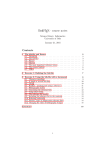
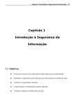
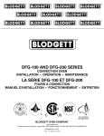
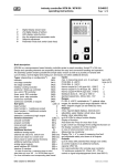
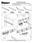
AC-500
HOT SURFACE IGNITION & I.I.D.SPARK IGNITION
VERTICALLY FIRED GAS CONVECTION OVEN
REPLACEMENT PARTS LIST
EFFECTIVE DECEMBER 31, 2003
BLODGETT OVEN COMPANY, 44 Lakeside Avenue, Burlington, Vermont 05401 USA
Telephone: (802) 860-3700 (800) 331-5842 Fax: (802) 860-3732
www.blodgett.com
Superseding All Previous Parts Lists.
The Company reserves the right to make substitution in the event that items specified are not available.
ERRORS: Descriptive and/or typographic errors are subject to correction.
www.blodgett.com
DECEMBER 31, 2003
2
AC500
TABLE OF CONTENTS
SERIAL NUMBER IDENTIFICATION CODE: RC / RF / RE
SERIAL NUMBER LOCATION / KEY:
IMPORTANT: When ordering parts, please provide the model, gas type
and serial number of the oven. The identification plate is located in the
bottom of the motor compartment on the right hand side and, also,
above the control panel under the ledge.
þ
t
ASAP Distributor Required Stocking Parts
Doors Are Not Returnable
CONTENTS
SIDE VIEW ......................................................................................
SOLID STATE MANUAL CONTROLS ...............................................
SOLID STATE DIGITAL CONTROLS ................................................
INTELLIPLUS CONTROLS ...............................................................
CH102 FAST CONTROLS .................................................................
GAS MANIFOLD ASSY, UNITS BEFORE 11/25/98 ............................
GAS MANIFOLD ASSY, UNITS AFTER 11/25/98 ..............................
INTERIOR VIEW ..............................................................................
DOOR COMPONENTS, SINGLE DOOR OPTION .............................
DOOR COMPONENTS, DOUBLE DOOR OPTION ............................
EXTERIOR VIEWS ...........................................................................
EXCLUSIVE TO EXPORT .................................................................
PAGE 3
PAGE 4
PAGE 5
PAGE 6
PAGE 7
PAGE 8
PAGE 9
PAGE 10
PAGE 11
PAGE 12
PAGE 13 & 14
PAGE 15
DECEMBER 31, 2003
3
AC500
SIDE VIEW, RIGHT HAND
OLD-BEFORE 01/01/97
NEW-AFTER 01/01/97
3
3
1
1
13
13
9
4
12
**See
NOTE
below.
12
7
2
NOTE:
Part is not depicted at
actual size.
Ref.
No.
Part
No.
1
30685
1
30685.H
34111
3
4
4
5
6
7
8
9
10
11
12
13
11
10
5
2
R
FO
RE ER
E
H MB
U
OK
LO IAL N
R
E
S
4
R
FO
RE ER
E
H MB
U
OK
LO IAL N
R
SE
31601
NOTE:
3574
21134
22711
30721
22190
M5495
18612
23007
R4435
R0364
R6490
34088
30957
15875
3807
30955
M0317
30952
5
6
2
**See
NOTE
below.
NOTE:
Part is not depicted at
actual size.
Description
Motor, 115V, 3/4 HP, 1 PH, 2 SP, 60 HZ
(Qty 1) Units before 01/01/97
Motor, 115V, 3/4 HP, "HOWELL"
Motor, 115V, 3/4 HP, 1 PH, 2 SP, 60 HZ
(Qty 1) Units after 01/01/97
Motor Adapter Bracket
For units before 01/01/97 this bracket will not
fit the Howell Motor.
Terminal Block, 65 AMP, 600V (Qty 1)
Axial Fan, 115V, 3" (Qty 3)
Lug, Grounding & Screw (Qty 1)
Harness, Wiring Power, Rear (Qty 1)
Dual Solenoid Valve/Pressure Regulator LP
Dual Solenoid Valve/Pressure Regulator NAT
Spring, Solenoid Valve, Nat to LP (Qty 1)
Spring, Solenoid Valve, LP to Nat (Qty 1)
Gas valve, manual
Knob, Square D, controls manual gas valve
Pilot Valve, Units after 01/01/97
Bracket, Pilot Valve, Units after 01/01/97
Flex Hose, 1/2" ID (Gas) (Qty 1)
Thru Pipe, Units before 01/01/97
Union, for thru pipe Units before 01/01/97
Thru Pipe, Units after 01/01/97
Elbow, 1/2"
Mounting Plate
8
30957
Flex Hose
**NOTE: this piece connects on the under side of
the manual gas valve.
DECEMBER 31, 2003
4
AC500
SOLID STATE MANUAL CONTROLS
3
10/
11
2
7
12
6
8
2
1
2
9
13
5
14
4
Ref.
No.
Part
No.
1
18578
30712
18234
24684
31839
2
3
2
4
5
2
6
7
8
9
21068
24684
20349
18225
24684
36755
18295
18296
18265
31274
10
31717
31767
11
12
13
14
15
16
17
33910
31363
31846
31841
R0364
R4435
NOTE:
30851
20348
Description
16 30851
Control - HSI
Units before 01/01/97
OR
20348
17
Spark Box
Units after
01/01/97
NOTE: Picture depicts Part 20348
Spark Box. Please use serial
number for correct part!!!
Controller, Temperature (Qty 1)
Probe, Temperature (Qty 1)
Potentiometer, Remote (Qty 1)
Knob, Temperature (Qty 1)
Bracket, Temperature Control Mounting
(Qty 1)
Mode Selector Switch (4 Position) (Qty 1)
Knob, Mode Selector (Qty 1)
Buzzer, 120V (Qty 1)
Timer, 60 Minute, 120V, 60 HZ (Qty 1)
Knob, Timer (Qty 1)
Thermal Switch SPDT, Units after 06/01/2003
Switch, Momentary for lights (Push-Button) (Qty 1)
Contact Block, 6 Amp., 600V (Qty 1)
Indicator Light, 28V, Red, Round (Qty 1)
Transformer, 120V to 24V
(Units before 01/01/97 use Qty 2 and Units after 01/01/97 use Qty 1)
Suppressor Assy (Qty 1) (for 31767)
Contactor, 3 Pole, 120V Coil (Qty 1)
Units before 01/01/97
Relay Assy Units after 01/01/97
Bracket, to mount 31767 (Qty 1)
Harness, Wiring Control (Qty 1)
Decal, Lexan Control (Manual) (Qty 1)
Knob, Square D, controls manual gas valve
Gas Valve, manual
Gas valves are pictured on page 3
Ignition Control, Hot Surface Ignition Units before 01/01/97
Spark Box Units after 01/01/97
DECEMBER 31, 2003
5
AC500
SOLID STATE DIGITAL CONTROLS (PICTURED WITH LIGHTS)
5 KEY
31767 Contactor
7 Before 1/1/97 OR
33910 Relay
8
After 1/1/97
3
4
9
5
2
1
6
11
12
30851
Ignition Control-HSI
Units before 01/01/97OR
10
14
NOTE: Picture depicts Part 20348
Spark Box. Please use
serial number for correct
part!!!
Ref.
No.
Part
No.
1
1
6
30658
FW529
30712
24685
21068
24684
19620
36755
31274
7
31767
8
33910
9
31363
31717
30720
31761
31921
31920
30851
20348
R0364
R4435
NOTE:
2
3
4
5
10
11
12
13
14
Description
Controller, Time & Temperature (Qty 1)
Controller, Reconditioned
Probe, Temperature (Qty 1)
Knob, Adjust Temperature (Qty 1)
Mode Selector Switch (4 Position) (Qty 1)
Knob, Mode Selector (Qty 1)
Light Switch, Rocker (Momentary) (Qty 1)
Thermal Switch SPDT, Units after 06/01/2003
Transformer, 120V to 24V
(Units before 01/01/97 use Qty 2 and Units after 01/01/97 use Qty 1)
Contactor, 3 Pole, 120V Coil (Qty 1)
Units before 01/01/97
Relay Assy (Qty 1)
Units after 01/01/97
Bracket, to mount 31767 (Qty 1)
Suppressor Assy (Qty 1) (for 31767)
Harness, Wiring Control (Qty 1)
Harness, Wiring Lights (Qty 1)
Control Panel & Decal (w/o Lights) (Qty 1)
Control Panel & Decal (w/ Lights) (Qty 1)
Ignition Control, Hot Surface Ignition Units before 01/01/97
Spark Box Units after 01/01/97
Knob, Square D, controls manual gas valve
Gas Valve, manual
Gas valves are pictured on page 3
20348
13 Spark Box
Units after
01/01/97
DECEMBER 31, 2003
6
AC500
INTELLIPLUS CONTROLS
13 KEY
8
3
4
31767 Contactor
Before 01/01/97
9 33910 Relay
After 01/01/97
10
5
4
6
7
30851 IgnitionControl
HSI - Before 01/01/97
or
14 20348 Spark Box - After
01/01/97
13
11
1
12
Ref.
No.
Part
No.
1
23391
31901
21443
18868
24684
19620
18265
31274
2
3
4
5
6
7
8
9
10
11
12
13
14
31767
33910
31363
31717
31761
34281
34254
R0364
R4435
R6490
NOTE:
30851
20348
NOTE: Picture depicts Part 20348
Spark Box. Please use serial
number for correct part!!!
Description
Controller, Temperature Intelliplus (13 Key) (Qty 1)
Probe, Temperature (Qty 1)
Knob, Control Time or Temperature (Qty 2)
Mode Selector Switch (3 Position) (Qty 1)
Knob, Mode Selector (Qty 1)
Light Switch, Rocker, Momentary (Qty 1)
Indicator Light, 28V, Red, Round (Qty 1)
Transformer, 120V to 24V
(Units before 01/01/97 use Qty 2 and Units after 01/01/97 use Qty 1)
Contactor, 3 Pole, 120V Coil (Qty 1) Units before 01/01/97
Relay Assy (Qty. 1) Units after 01/01/97
Bracket, to mount 31767 (Qty 1)
Suppressor Assy. (Qty 1) (for 31767)
Harness, Wiring Lights (Qty 1)
Harness, Wiring front Intelliplus Units after 01/01/97
Decal, Lexan Control
Knob, Square D, controls manual gas valve
Gas Valve, manual Units before 01/01/97
Pilot Valve Units after 01/01/97
Gas valves are pictured on page 3
Ignition Control, Hot Surface Ignition Units before 01/01/97
Spark Box Units after 01/01/97
DECEMBER 31, 2003
7
AC500
CH102 FAST CONTROLS
(WITH LIGHTS) 14 KEY
4
6
2
3
1
5
8
7
9
Ref.
No.
Part
No.
1
37087
34472
19620
24685
21068
31274
36755
33910
20348
34689
35187
2
3
4
5
6
7
8
9
34406
31761
34453
24623
36056
R0364
Description
Controller, CH102 (14 Key)
Probe, RTD 12"
Light Switch, Rocker, DPST, Momentary
Knob, Adjust (Qty 1)
Mode Selector Switch (4 Position) (Qty 1)
Transformer, 120V to 24V (Qty 1)
Thermal Switch SPDT, Units after 06/01/2003
Relay Assy (Qty 1)
Spark Box Assy, Nat & LP (Qty 2)
Capacitor Assy, Snubber CH102 control
Jumper Wires, Rear connecting
CH102 control
Harness, Wiring Control
Harness, Wiring Lights
EMI Filter CH102 control
RFI Filter CH102 control
Control Panel & Decal Assy, CH102
Knob, Square D, controls manual gas valve
1
DECEMBER 31, 2003
8
AC500
GAS MANIFOLD ASSEMBLY
FOR UNITS BEFORE 11/25/98
SERIAL NUMBER 112598RF008T
2
1
3
5
3
4
2
1
6
4
40
4
7
Ref.
No.
Part
No.
1
2
3
4
5
5
6
31022
30774
31331
30722
30943
31828
30713
30958
31829
7
30957
33052
33051
Description
Ignitor, Hot Surface (Qty 2)
Bracket Assy, Ignitor (Qty 2)
Probe, Flame Sensing (Qty 2)
Burner Assy. (Qty 2)
Orifice, Main Burner, Nat (MTD #46) (Qty 4)
Orifice, Main Burner, LP (MTD #55) (Qty 4)
Manifold, Burner (Qty 1)
Manifold Assy, Nat (w/ Harness) (Qty 1)
Complete assy as shown above
Manifold Assy, LP (w/ Harness) (Qty 1)
Complete assy as shown above
Flex Hose, 1/2" ID (Gas) (Qty 1)
Relay & Hardware 24V, for Gas sytem
shutoff
Relay & Hardware 240V, for Gas system
shutoff
Ref.
No.
Part
No.
Description
NOTE:
Hot Surface Ignition is standard on units
.
before 01/01/97, however the manifold
changes did not occur until 11/24/98.
PLEASE BE SURE TO HAVE SERIAL
NUMBER when ordering ANY gas components
DECEMBER 31, 2003
9
AC500
GAS MANIFOLD ASSEMBLY
FOR UNITS AFTER 11/25/98
SERIAL NUMBER 112598RF008T
7
5
1
7
3
1
11
2
5
6
9
2
6
11
10
4
8
Ref.
No.
Part
No.
Description
1
2
2
3
30722
30943
31828
33860
30713
NOTE:
Burner Assy (Qty 2)
Orifice, Main Burner, Nat (MTD #46) (Qty 4)
Orifice, Main Burner, LP (MTD #55) (Qty 4)
Manifold, Burner Units after 11/25/98
Manifold, Burner Units before 11/25/98
See picture on page 8
31604
Harness, Wiring Manifold (Qty 1)
Units after 11/25/98
Manifold Assy, Nat (w/ Harness) (Qty 1)
Units after 11/25/98
Manifold Assy, LP (w/ Harness) (Qty 1)
Units after 11/25/98
Elbow, Union Compression
Pilot Ignitor Assy (Qty 2)
Pilot Shield
Bracket, Pilot Shield
Flex Hose, 1/2" ID (Gas) (Qty 1)
Tubing, Flex 24" (Qty 1)
Tubing, Flex 12" (Qty 1)
Pilot Orifice Nat (Qty 2)
Pilot Orifice LP (Qty 2)
33552
33553
4
5
6
7
8
9
10
11
11
M2799
34282
33536
33537
30957
33837
33488
M0697
M2690
Ref.
No.
Part
No.
NOTE:
Description
Direct Spark is standard on units after
01/01/97, however the manifold changes
did not occur until 11/24/98. PLEASE BE
SURE TO HAVE SERIAL NUMBER when
ordering ANY gas components.
DECEMBER 31, 2003
10
AC500
INTERIOR VIEW
4
3
1
1
2
Ref.
No.
1
2
3
4
Part
No.
Description
30988
30677
30676
30649
30695
30694
31741
31836
31837
31763
Retainer, Probe Wire (Qty 2)
Rack Support (Qty 2)
Rack, Wire (27-3/8" x 23-5/16") (Each)
Blower Wheel (Qty 1)
Baffle Assy., Interior Porcelain (Qty 1)
Support Assy., Baffle (Qty 4)
Bulb, Light 25W, 120V, (Qty 2)
Socket Assy., Light (Qty 2)
Reflector Assy., Light (Qty 2)
Lens, Cover Light (Qty 2)
DECEMBER 31, 2003
11
AC500
DOOR COMPONENTS-SINGLE DOOR OPTION
8
5
9
6
1
7
10
2
5
OLD-BEFORE 01/01/97
t
Ref.
No.
Part
No.
Doors Are Not Returnable
NEW-AFTER 01/01/97
t
Doors Are Not Returnable
Description
AFTER JANUARY 01, 1997
t 33933
Door Assy, Solid (Qty 1)
1 t 33886
Door Assy, Glass (Qty 1)
2
31704
Glass Assy, Door (14" x 20") (Qty 1)
3
R6313
Handle
4
R2296
Catch & Latch Assy
20734
Microswitch Assy, Pictured on page 12
33907
Bracket, Door Switch
5
30761
Arm, Door Upper &/or Lower (Qty 2)
31919
Gasket Assy, Perimeter Door (4 Piece) (Qty 1)
Pictured on page 12
16470
Nameplate Assy., Blodgett 10" (Qty 1)
BEFORE JANUARY 01, 1997
6 t 30770
Door Assy, Sld (Qty 1)
t 31770
Door Assy, Gls (Qty 1)
2
31704
Glass Assy, Door (14" x 20") (Qty 1)
7
30680
Handle, Door (Qty 1)
8
17946
Catch Assy, Door (Qty 2)
NOTE:
One is located on the top of the door and
the other is located on the bottom of the door
31206
Plate, Striker Door Latch (Qty 2)
31240
Microswitch Assy, Door Pictured on page 12
30940
Bracket, Door Switch (Qty 1)
9
35883
Arm, Door Upper (Qty 1)
10
35884
Arm, Door Lower (Qty 1)
90004
Bushings, Door Hinge (Set of 2)
31772
Cam Assy, Door Switch (Qty 1)
31919
Gasket Assy, Perimeter Door (4 Piece) (Qty 1)
Pictured on page 12
16470
Nameplate Assy., Blodgett 10" (Qty 1)
31747
Decal, Logo "The Achiever" (Qty 1)
3
4
FOR UNITS AFTER 01/01/97
DECEMBER 31, 2003
12
AC500
DOOR COMPONENTS
SPECIFIC TO DOUBLE DOOR OPTION
3
2
1
4
5
6
Ref.
No.
1
2
3
4
5
6
Part
No.
t 31721
t 36113
31753
31723
31751
31752
36098
37305
31772
36118
31919
37304
Description
Door Assy, LH Glass (Qty 1)
Door Assy, RH Glass (Qty 1)
Catch Assy, Door
Striker Plate, for Catch Assy.
Door Arm Assy, LH
Door Arm Assy, RH
Combustion Compt. Cover
Microswitch Assy
Cam Assy, Switch
Handle Assy, Qty 2
Gasket Assy, Perimeter
Gasket Assy, Center
DECEMBER 31, 2003
13
AC500
EXTERIOR VIEW "OLD STYLE" BEFORE 01/01/97
1
4
NO
TR
EP
LAC
EA
BLE
12
6
3
5
2
12
NOTE: The Microswitch
is located behind this
louvered cover piece.
EXTERIOR VIEW "NEW STYLE" AFTER 01/01/97
8
1
12
9
33545
Body Top
10
12
7
1
NOTE: The Microswitch
is located behind this
louvered cover piece.
DECEMBER 31, 2003
14
EXTERIOR OVEN COMPONENTS
SEE PICTURES ON PAGE 13
Ref.
No.
1
12
Part
No.
Description
7839
7840
30986
31919
33461
21826
21242
31595
8598
92000
7847
32215
32216
31679
16002
19528
33425
Drafthood, Direct Venting, S/S (Qty 1)
Draft Diverter, Canopy Venting, S/S (Qty 1)
Flue Box, Sgl Oven (Qty 1)
Gasket Assy, Perimeter
Vent Assy, Complete
Installation Hose, 36"
Installation Hose, 48"
Cord Set Assy, 6 Feet (Qty 1)
Legs, 25" w/ Bolts, S/S (Set of 4)
Studs, Leg (Set of 4)
Bolts, Leg (Set of 8)
Open Stand w/ Feet, S/S
Open Stand w/ Casters, S/S
Backpipe Assy, Dbl (Qty 1)
Casters (Sgl Oven) (Set of 4)
Casters, Low Profile (Dbl Oven) (Set of 4)
Casters, Adjustable Low Profile (Dbl Oven) (Set of 4)
BEFORE JANUARY 01, 1997, SEE PICTURES ON PAGE 12
2
30975
Cover Assy, Combustion Compartment (Qty 1)
3
30971
Body Side, RH S/S (Qty 1)
4
30974
Body Top, Front (Qty 1)
30967
Body Back, S/S (Qty 1)
5
30718
Cover, Control (Qty 1)
6
31240
Microswitch Assy, Door (Qty 1)
Units before 01/01/97
AFTER JANUARY 01, 1997, SEE PICTURES ON PAGE 12
7
33546
Cover Assy, Combustion Compartment (Qty 1)
8
33891
Body Side, RH S/S (Qty 1)
9
33545
Body Top (Qty 1)
10
33887
Panel, Front Trim
11
20734
Microswitch Assy, Door (Qty 1)
Units after 01/01/97
AC500
DECEMBER 31, 2003
15
EXCLUSIVE TO EXPORT
Ref.
No.
Part
No.
32241
M2453
32237
16037
20084
18581
18439
32231
32277
20350
32258
32243
32233
32992
R4435
32236
32282
32306
M3330
32234
32327
Gas Valve, Manual 1/2" (Qty 1) CE
Gas Valve, Honeywell 240V (Qty 1) CE
Thru Pipe Assy (Qty 1) CE
Switch Assy, Pressure (Qty 1) CE
Switch, Pressure (Netherlands) (Qty 1) CE
Manifold Assy, Nat (Qty 1) CE
Manifold Assy, LP (Qty 1) CE
32206
32242
32290
32238
Control, Hot Surface Ignitor (Qty 2) CE
Ignitor, Hot Surface (Qty 2) CE
Thru Pipe & Nozzle Assy., Steam (Qty 1) CE
Nozzle Assy, Humidaire 230V (Qty 1) CE
32305
32307
32308
M2841
Bracket, Vacuum Pipe (Qty 1) CE
Pipe, Vacuum 9.75" (Qty 1) CE
Pipe, Vacuum 8.0" (Qty 1) CE
Fitting, Pressure Tap (Qty 1) CE
32212
Decal, Lexan Control (Infinite & Humidaire)
(Qty 1) CE
Decal, Lexan Control (Infinite) (Qty 1) CE
32295
NOTES
Description
Motor, 240V, 2 SP, 50/60 HZ
Switch, Thermal High Limit (Qty 1) Units before 01/01/97
Bulb, Light 25W, 230-240V (Qty 2) CE
Indicator Light, 250V, Red, Round (Qty 1) CE
Timer, 60 Minute, 240V, 50 HZ (Qty 1) CE
Timer, Adjustable, 240V (Qty 1) CE
Potentiometer, Control (Humidaire) CE
(Qty 1)
Switch, Momentary (Lighted) CE
(Qty 1) or (Qty 2)
Switch, Momentary (Qty 1) CE
Contactor, 3 Pole, 230V Coil (Qty 1) CE
Buzzer, 240V (Qty 1) CE
Harness, Wiring Rear Humidaire (Qty 1) CE
Harness, Wiring Front Humidaire (Qty 1) CE
Harness, Wiring Front (Qty 1) CE
Harness, Wiring Rear CE
32230
AC500
BLODGETT OVEN COMPANY, 44 Lakeside Avenue, Burlington, Vermont 05401 USA
Telephone: (802) 860-3700 (800) 331-5842 Fax: (802) 860-3732
www.blodgett.com