1
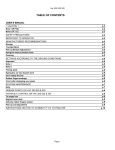
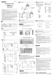
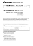
CD
PWR
RK
N/T
TU
MIX
AUD
Robert Bosch Corporation
Sales Group —
Blaupunkt Division
2800 South 25th Avenue,
Broadview, Illinois 60155
Issue date 03-01
288F0170
RPD552_Cover
1
2/15/01, 6:03 PM
RPT
AM
ESPAÑOL
ISP
NS D
LD/SE
VOL
FM
TS
552
RPD
PORTUGUÊS
210
ENGLISH
High-Power FM/AM/CD Receiver with Detachable Face
Autoradio AM/FM à Lecteur CD de Forte Puissance et à Face Amovible
Receptor FM/AM/Reproductor de CD de Alta Potencia y con Panel Extraíble
Rádio FM/AM/CD de Alta Potência
com Face Removível
FRANÇAIS
RPD 552
Precautions
This equipment has been tested and found to comply with the
limits for a Class B device, pursuant to Part 15 of the FCC Rules.
These limits are designed to provide reasonable protection
against harmful interference in a residential installation. This
equipment generates, uses, and can radiate radio frequency
energy, and, if not installed and used in accordance with instructions, may cause harmful interference with radio communications. However, there is no guarantee that radio interference will not occur in particular installation. If this equipment
does cause harmful interference to radio or television reception, which can be determined by turning the equipment off and
on, the user is encouraged to consult the dealer or an experienced radio/TV technician for help.
You are cautioned that any changes or modifications not expressly approved in this manual could void your authority to
operate this equipment.
• Carefully read this manual before using the unit. If you encounter any problems that are not covered in this manual,
please consult the dealer where you purchased the unit or
the dealer nearest to you.
• Avoid installing the unit where it would be subject to high temperatures, such as in direct sunlight or a hot air stream from
the heater, or where it would be subject to dust, dirt, or excessive vibration.
• Do not turn on the unit if the temperature inside the car is
very high. Always cool down the unit before usage. Parking
your car in direct sunlight will result in a temperature rise.
• If the unit does not turn on, check the connections first. Then
check whether the fuse at the back of the unit is blown.
• This unit has been designed specifically for playback of compact discs bearing the
mark. Other discs cannot be
played.
• Do not use non-conventional discs such as heart-shaped,
octagonal discs, etc. The player could be dameged.
Features
Handling the Front Panel
• Detachable front panel
Handling Compact Discs
• Built-in power amplifier
(max. output : 52.5W × 4ch)
• Be careful when removing a compact disc after the playback
is completed because the disc may be extremely hot.
• Do not expose compact discs to direct sunlight or any direct
heat source.
• Check all compact discs before playing, and discard cracked,
scratched or warped discs.
• Wipe dirty or damp discs outward from the center with a soft
cloth.
• Do not use any solvent such as commercially available cleaners, antistatic spray, or thinner to clean the compact discs.
• Digital 12-hour quartz clock
• FM/AM PLL synthesizer tuner
• 30 Station preset memory
• Auto Store / Scan tuning
• 2-ch preamp output
Attaching the Front Panel
Place the right hand side of the front panel so that the parts A
of the front panel are engaged with the parts B of the unit as
shown below. Then push the left hand side of the front panel
until it is securely locked.
Detaching the Front Panel
Remove the CD from the unit, if any, and turn off the power of
the unit.
Press the REL to unlock the front panel from the unit. Grasp
the front panel as shown below and remove it from the unit.
Security
To avoid theft or loss of the front panel, you can deactivate the
release button REL by installing the locking screw provided.
1.
Unscrew the bolt marked
(See diagram above)
2.
3.
Attach the front panel.
* at the left front side of the unit.
Select a locking screw from the mounting hardware (See
page 6) and screw it into the same hole to fasten the front
panel.
Notes
• Do not press hard on the front panel when affixing it to the
unit. No more than light to moderate pressure should be
needed.
• Make sure there is no dust or dirt on the electrical terminals
on the back of the front panel as this could cause intermitent
operation or other malfunctions.
E-1
RPD552_p.1-9 (E)
1
2/16/01, 10:23 AM
ENGLISH
FCC WARNING
ENGLISH
Identification of Controls
RPD 552
AUD
1
2
3
4
5
6
7
8
9
10
REL button
Releases the detachable front panel.
CD insertion slot
Insert the CD here.
LCD Display window
PWR button
Turns the power of the unit on. Mute on/off during power on.
Press for more than 2 seconds to turn off.
Eject button
Ejects the CD.
CD button
Switches the CD playback mode.
FM button
Selects the FM Band & FM Travel store.
AM button
Selects the AM Band & AM Travel store.
DISP button
Display selector. Clock adjustment.
LD/SENS button
Switches the reception sensitivity between local and distance.
Loudness on/off.
210
CD
PWR
/ TR K
TUN
VOL
FM
TS
MIX
LD/SENS DISP
RPT
AM
11 PRESET MEMORY button
During radio reception :
1
- 6/
; For Preset memory
During CD mode :
4/MIX
; For Mix play
5/RPT
; For Repeat play
; For Pause
12 AUD button
Audio control selector; Bass, Treble, Balance, Fader & Mute level.
Mute level is selectable.
13
/
button
Used to tune in to the desired station.
Adjusts the bass/treble/balance.
14
/
button
Scan/Preset scan tuning. Scan play in CD mode.
Adjusts the bass/treble/fader.
15 VOL + / – button
Adjusts the volume and mute level.
Mute is adjustable from 0 to -80.
6/
E-2
RPD552_p.1-9 (E)
2
2/16/01, 10:24 AM
Power On/Off
Turning on the power
Press the
to turn on the unit.
PWR
Turning off the power
Press the
Adjusting the Sound Characteristics
Press the VOL /
to adjust the volume level.
: Volume up
: Volume down.
1.
Press the AUD to select the desired adjustment mode.
BASS ➜ TREBLE ➜ BALANCE & FADER ➜ Mute level
2.
Press the following buttons to adjust the selected item. Make
the adjustment within 5 seconds after selecting. After 5
seconds, the display window will revert to previous indication.
You can check the volume level visually with the indicators in
the display window.
for more than 2 seconds.
PWR
Volume Level Control
Volume level meter
Setting the Clock
The clock uses a 12-hour display system.
1.
2.
3.
4.
Turn the ignition key to the ON position.
Press the
PWR
to turn on the unit.
Press the DISP and hold 2 seconds to start.
Use the following buttons to set the clock. (The blinking
section can be adjusted.)
/
: Adjust the Hour and minute
: To activate Hour blink
: To activate Minute blink
Press the
DISP
to activate the clock.
BASS
/
TREBLE
/
BALANCE
Muting the Sound
Briefly press PWR while the receiver is on.
on the display
While muting the sound, the MUTE indicator
is blinking.
To restore the previous volume level, press PWR again.
Adjustment Range
BASS -7 BASS 7
TREB -7
L
9 (Full left)
FADER
F
MUTE LEVEL
(-80)
9 (Full front)
TREB 7
R
R
/
/
9 (Full right)
9 (Full rear)
(-0)
You can check the each level visually with the indicators in the
display window.
Center level mark
Loudness Effect
When listening to music at low volume levels, this feature will
boost the extremes of the bass and treble ranges to compensate for the negative characteristics of human hearing.
Ignition-off Clock Call
The display will illuminate showing the time and then automatically shut off after 5 seconds.
Briefly press the DISP while the ignition switch is in the “ OFF ”
position to activate.
BALANCE
Press the LD/SENS .
The “LD” indicator appears in the display window.
Pressing this button again will cancel this feature.
FADER
Display Selector
Each time the DISP is pressed, the display window will change
as shown below;
• Radio mode
Frequency and Clock.
• CD mode
Elapsed track time and clock.
E-3
RPD552_p.1-9 (E)
3
2/16/01, 10:24 AM
ENGLISH
General Operations
ENGLISH
Radio Reception
Seek Tuning
Preset Scan Tuning
1.
1.
2.
2.
Press the AM or FM to select the desired band.
FM I ➜ FM II ➜ FM III
or
AM I ➜ AM II
Press the
or
to tune in stations. Seek tuning automatically stops at a broadcasted frequency.
When tuning to FM stereo broadcasting stations, the
“
” stereo indicator will light up in the display window.
Manual Tuning
1.
2.
Press the
AM
or
Press the
AM
or
FM
Receiving the Memorized Stations
to select the desired radio band.
Press the
.
The unit will scan preset memory for the 12 stations from
the AM I/AM II band or the 18 stations from the FM I or FM
II and FM III bands. The unit will stop at each preset station for 8 seconds, before continuing to the next preset station.
again to stop Preset Scan Tuning and rePress the
main this on the selected frequency.
Memorizing Stations Automatically (Travel Store)
FM
to select the desired band.
Press the
or
and hold for more than 0.5 second
to activate the manual tuning mode. Press again to tune in
to stations.
After 4 seconds duration of completing Manual Tuning, the
tuning control will revert to the Seek Tuning mode.
1.
2.
Press the
AM
or
FM
to select the desired band.
Hold the AM or FM pressed for longer than 2 seconds.
Up to 6 stations with strong signals will be automatically
stored in preset memory for the selected band.
1.
2.
Press the
AM
Press the
1
AM
or
FM
to select the desired radio band.
Press the
.
The unit will scan the selected radio band for stations.
again to stop Scan Tuning and remain on
Press the
this selected frequency.
Tips
When tuned in to broadcasting stations, the antenna indicator
on the display window is lit.
Memorizing Only the Desired Stations
A total of 30 stations (18 for the FM I, FM II and FM III, 12 for
AM I and AM II) can be stored in preset memory.
Press the
Press the
AM
or
or
FM
to select the desired radio band.
to tune in stations.
Press and hold the desired preset memory button 1 6/
for about 2 seconds until the frequency indicator
flashes twice.
The number of the pressed preset memory button appears
on the display window.
Note
If/when you store another station on the same preset number
button, the previously stored station is replaced with new one.
E-4
RPD552_p.1-9 (E)
4
to select the desired radio band.
momentarily.
Press the LD/SENS for more than 2 seconds to select the Local
setting and only the strongest (local) stations will be received.
The “lo” indicator appears in the display window.
Pressing again for 2 seconds will select the Distant setting and
the radio will stop at a wider range of signals, including weaker
more distant stations. The “lo” indicator will go out on the display window.
The “Distant” setting is the recommended default mode of reception.
Note
1.
2.
3.
FM
This feature is used to select the strength of the signals at which
the radio will stop during Seek Tuning.
This function is available for FM III and AM II.
Press the
-
6/
Local/Distant (LO/DX) Selection
Scan Tuning
1.
2.
or
2/16/01, 10:24 AM
Playing the CD player
Listening to a disc that is already loaded
Scan Play
Loading Discs
Press the CD to select the CD mode.
Playback begins automatically.
Press the
during CD mode.
The ‘‘SCAN’’ indicator appears in the display window. This will
play the first 10 seconds of all the tracks on the disc.
Press the
again to cancel this feature.
Insert the disc into the CD insertion slot with the labeled side
facing up.
’’ indicator will light up in the display window and play‘‘
back begins automatically.
Pausing Playback
Press the 6/ .
To resume playback, press the
6/
again.
Repeat Play
Stopping Playback
Press the
Labeled side up
or
AM
FM
Press the 5/RPT during CD mode.
The ‘‘RPT’’ indicator appears in the display window and the current track is played repeatedly.
Press the 5/RPT again to cancel this feature.
to select the radio reception.
Ejecting Discs
Press the
to eject the disc.
Note
MIX Play
■ NEVER Insert 3-inch CD’s.
The unit will turn-on automatically when a CD is inserted if the
ignition switch is ‘‘ON’’.
This unit is designed for playback of standard 5-inch CD’s only.
Do not attempt to use 3-inch CD singles in this unit, either with
or without an adaptor, as damage to the player and/or disc may
occur.
Playing a CD in various modes
Press the 4/MIX during CD mode.
All the tracks on the current disc are played in random order.
Press the 4/MIX again to cancel this feature.
Track Search
Tip/FYI
During playback of a CD, the pie-shaped indicator
spins.
Press the
or
during CD mode. Track numbers appear
in the display window.
: Playback starts from the beginning of the next track.
: Playback starts from the beginning of the current track.
Press again to play the previous track.
Cue / Review
Press and hold the
or
during CD mode.
Release when you have found the desired point.
: To search forward.
: To search backward.
E-5
RPD552_p.1-9 (E)
5
2/16/01, 10:24 AM
ENGLISH
CD Operations
Installations
Mounting Example
ENGLISH
Supplied Mounting Hardware
Bushing Use
Installation in the dashboard.
1.
Sleeve
Bushing,
Screw
3.
Install the sleeve in the dashboard.
*
As shown in the figure below, securely fasten the screw,
which has been inserted into the bushing, at the rear of the
unit.
Locking Mounting Strap Release
Screw
and Screws
Keys
Removal trim ring
(Supplied)
Fire wall
Precautions
• Be sure to remove/detach the front panel before you start
installing the unit.
• Choose the mounting location carefully so that the unit will
not interfere with the normal driving operations of the driver.
• Use only the supplied mounting hardware for a safe and secure installation.
• Handle the sleeve carefully to avoid injuring your fingers.
• When mounting the unit in a car, keep the unit as level as
possible. If the unit must be mounted at an angle, due to the
design of the vehicle, make sure that the unit does not tilt
upward by more than 30°.
2.
Select and bend the appropriate tabs to hold the sleeve
firmly in place.
The distance to the fire wall varies due to the
type of the car. Be sure to secure the unit by
properly inserting the bushing.
Mounting Strap Use
3.
*
Caution
Attaching the Mounting Strap to the underside of the dash
board, using screw.
Attach the back of the unit to the Mounting Strap using the
support stem bolt and hardware.
Fire wall
Removal trim ring
(Supplied)
Insufficient fastening of the screw may cause
some CD’s to skip.
* Warning
Failure to properly install the Mounting Strap or rear support
Bushing is a major cause of CD skipping. Without these securing devices, the chassis of the CD receiver is able to move up &
down whenever the road has imperfections and CD skipping
results.
Note
Some Japanese/Asian vehicles such as TOYOTA & NISSAN do
not require use of the sleeve and trim ring assembly.
To secure the replacement radio use the O.E.M. brackets and
mounting screws. These brackets will align with the threaded
screw holes found on each side of the new radio.
E-6
RPD552_p.1-9 (E)
6
2/16/01, 10:24 AM
Connections
Warning
ANTENNA SOCKET
ANTENNA PLUG
In the case of a 2-speaker system,
tape the ends of unconnected
terminals to prevent short circuit
4-speaker System
Connection procedure
(White/Black)
(Gray)
(Gray/Black)
• DO NOT connect any speaker wires to the metal body or chassis of the vehicle.
• DO NOT connect the speaker common (-) wires to each other.
• Connect each speaker wire directly to each speaker terminal.
• All speaker common (-) wires must remain floating.
i.e. No Common Connections or connections to vehicle grd
.
• Connect each pair of speaker leads only to a single speaker
(or speaker system) that has an impedance of least 4 ohms,
as well as 50-watt power-handling capability.
• Do not connect speaker leads to any inputs on external amplifiers. This will cause damage to the internal amplifier of this
unit.
1
2
3
4
5
6
7
8
9
2-speaker System
(White)
Caution
Make sure the car’s ignition key has been removed.
Disconnect the negative (-) terminal of the car’s battery.
Connect the wiring harness wires in the following
order : Ground wire (Black), +12V Constant Power
Supply (Yellow), +12V Accessory/Switched (Red) and
Power Antenna/Amplifier Turn On (Blue), and tape each
so they do not come in contact with each other.
Connect the speaker wires of the wiring harness.
Connect the car’s antenna terminal to the antenna
socket of the unit.
Connect the detachable wire harness to the unit.
Reconnect the negative (-) terminal of the car’s battery.
Start the car’s engine.
Make sure the unit operates properly.
ENGLISH
Connection procedure
• To prevent short circuit, remove the key from the ignition and
disconnect the battery’s (-) terminal.
• This unit is designed for negative ground 12 V DC operation
only. You can not use it for 24 V or other types of car batteries.
(White)
Front Left
Speaker
Front Right
Speaker
(Green)
(Green/Black)
(Violet
(Violet/Black)
(White/Black)
Left
Speaker
(Gray)
(Gray/Black)
Right
Speaker
(Green)
Rear Left
Speaker
Rear Right
Speaker
(Green/Black)
(Violet
(Violet/Black)
Do Not
Connect
Do Not
Connect
+12V Constant Power Supply (Yellow)
+12V Accessory/Switched (Red)
Ground Wire (Black)
Power Antenna/Amplifier Turn On (Blue)
Preamp Out/Line Out Connections
• Since this unit has Line Level Outputs, you can use an amplifier to upgrade your vehicle stereo system.
RCA Line-out Jacks
White (Left)
Red (Right)
External Amplifier
Rear Speaker
RCA Line-out Jacks (For Rear Speakers)
• Connect a patch cable (not supplied) from the White (left rear channel) and Red (right rear channel) RCA line output jacks of the
unit to the line input terminals of the external amplifier.
E-7
RPD552_p.1-9 (E)
7
2/16/01, 10:24 AM
ENGLISH
Maintenance
Replacing the Fuse
Removing the Unit
If the fuse is blown, check the power connection first and then
replace the fuse. If the fuse blows again under normal conditions, the unit may be defective.
Use the supplied release keys when you need to remove the
unit from the car.
Insert them into the unit as shown below. This will unlock the
unit from the sleeve, allowing for removal of the unit.
Back of the unit
Notes
Warning
Use only a fuse with the specified amperage (10 A).
Use of another type of fuse can result in a fire or unit damage.
• Handle the release keys carefully to avoid injuring your fingers.
• Keep the release keys in a safe place for future use.
Cleaning the Connectors
If the connectors of the unit and the front panel are contaminated, malfunctions may occur.
Detach the front panel and clean the connectors with an alcohol dampened cotton swab as shown below.
Main unit
Back of the front panel
Returning to the Initial Settings
When the reset button is pressed, the microcomputer of the
unit returns to the initial settings. If the display window is not
properly shown or the unit malfunctions, press the reset button
with the point of a sharp object such as a ball-point pen.
E-8
RPD552_p.1-9 (E)
Reset button
8
2/16/01, 10:24 AM
Troubleshooting Guide
Specifications
General
Trouble
• Memorized stations and correct time are erased.
• The fuse has blown.
• Radio works when the ignition
key is in the ON, ACC and OFF
positions.
• No power is being supplied to
the unit.
• The power is continuously supplied to the unit.
Cause/Solution
Leads are not matched
correctly with the car’s accessory power connector.
Check wiring for short circuits.
CD Player Troubleshooting
When problems occur with CD playback, an error message
appears in the display window.
Refer to the table below to identify the problem, then take the
suggested corrective action. If the error persists, contact your
nearest Blaupunkt dealer.
Message
Possible cause
Recommended action
E-01
Dirty disc.
Scratched disc.
Up-side-down.
Clean the disc.
Replace the disc.
Check the disc.
E-02
Focus error.
Try ejecting and re-inserting under normal temperature conditions.
E-03
Data and focus error.
Under normal temperature conditions, eject and
insert clean, undamaged
disc properly.
The car doesn’t have an
ACC position.
Radio reception
Trouble
Preset stations are not receivable.
Cause/Solution
The broadcast signal is too weak.
Seek tuning is not possible.
The broadcast signal is too weak.
→ Use manual tuning.
Travel Store feature does
not complete storing of six
stations
Not enough broadcast frequencies are receivable.
GENERAL
E-04
Mechanical problem.
Eject and re-insert.
: Approx. 178 mm × 50 mm × 155 mm
(W × H × D)
Power requirements : 12 volts DC car battery
(negative ground)
Output Power
: 52.5 watts × 4 channels
Output Wiring
: Floating-ground type designed for 2 or
4 speaker use.
RCA low-level outputs (2 channels).
Output Impedance : Compatible with 4-8 ohm speakers.
Low - Level Output : 2 V.
Dimensions
TUNER
Tuning Range
Sensitivity
FM
Stereo Separation
: AM : 530 - 1, 710 kHz
(10 kHz step)
FM : 87.5 - 107.9 MHz
(200 kHz step)
: AM : 20 µV
FM : 1.5 µV
: 30 dB
CD PLAYER
Frequency
Response
S/N Ratio
Wow & Flutter
: 20 - 20,000 Hz
: 98 dB
: Below the measurable limit
Also make sure that antenna is connected, extended and dry
inside.
If the above mentioned solutions do not help to improve the
situation, consult your nearest Blaupunkt dealer or in the United
States call 1-800-266-2528 for technical assistance, parts and
service. Call 1-800-950-2528 for dealer referral or to request
product brochure.
E-9
RPD552_p.1-9 (E)
9
2/16/01, 10:24 AM
ENGLISH
The following check will assist in the correction of most problems which you may encounter with your unit. Before going
through the check list below, refer back to the connection and
operating procedures.