1
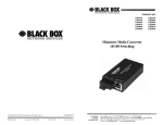
LGC300A-R2
Industrial SFP/SFP Multi-Power Mode Converter
Converts any fiber optics type interface
to any other fiber optics type interface.
FCC and IC RFI Statements
FCC and Industry Canada RF Interference Statements
Class B Digital Device. This equipment has been tested and found to comply
with the limits for a Class B computing device pursuant to Part 15 of the FCC
Rules. These limits are designed to provide reasonable protection against
harmful interference in a residential installation. However, there is no guarantee
that interference will not occur in a particular installation. This equipment
generates, uses, and can radiate radio frequency energy, and, if not installed and
used in accordance with the instructions, may cause harmful interference to radio
communications. If this equipment does cause harmful interference to radio or
telephone reception, which can be determined by turning the equipment off and
on, the user is encouraged to try to correct the interference by one of the
following measures:
• Reorient or relocate the receiving antenna.
• Increase the separation between the equipment and receiver.
• Connect the equipment into an outlet on a circuit different from that to which
the receiver is connected.
• Consult an experienced radio/TV technician for help.
CAUTION
Changes or modifications not expressly approved by the party responsible for
compliance could void the user’s authority to operate the equipment.
To meet FCC requirements, shielded cables and power cords are required to
connect this device to a personal computer or other Class B certified device.
This digital apparatus does not exceed the Class B limits for radio noise
emission from digital apparatus set out in the Radio Interference Regulation
of Industry Canada.
Page 2
724-746-5500 | blackbox.com
LGC300A-R2
Certifications
Certifications
Class 1 Laser product, Luokan 1 Laserlaite,
Laser Klasse 1, Appareil A’Laser de Classe
European Directive 2002/96/EC (WEEE) requires that any equipment that
bears this symbol on product or packaging must not be disposed of with
unsorted municipal waste. This symbol indicates that the equipment should
be disposed of separately from regular household waste. It is the
consumer’s responsibility to dispose of this and all equipment so marked
through designated collection facilities appointed by government or local
authorities. Following these steps through proper disposal and recycling will
help prevent potential negative consequences to the environment and
human health. For more detailed information about proper disposal, please
contact local authorities, waste disposal services, or the point of purchase for
this equipment.
LGC300A-R2
724-746-5500 | blackbox.com
Page 3
Table of Contents
Table of Contents
Part Numbers ...................................................................................................... 5
1.
Specifications ......................................................................................... 6
1.1
Standards/Compliance ........................................................................... 6
2.
Overview: About the Industrial SFP/SFP Multi-Power Mode
Converter................................................................................................ 7
2.1
Features ................................................................................................. 7
3.
Install the Industrial SFP/SFP Multi-Power Mode Converter ................. 8
3.1
SFP Port Requirements ......................................................................... 8
3.2
DIN Rail Mounting .................................................................................. 8
3.3
Powering the Industrial SFP/SFP Multi-Power Mode Converter ........... 8
3.3.1
DC Terminal Block Option ............................................................. 9
3.3.2
Cascading DC Power .................................................................... 9
3.4
DC Power Supply Precautions............................................................. 10
4.
Operation.............................................................................................. 11
4.1
LED Operation...................................................................................... 11
5.
Contacting Black Box ........................................................................... 12
6.
Fiber Optic Cleaning Guidelines .......................................................... 13
7.
Electrostatic Discharge Precautions .................................................... 14
Page 4
724-746-5500 | blackbox.com
LGC300A-R2
Part Numbers
Part Numbers
Part Number
LGC300A-R2
LGC300A-R2
Description
MultiPower SFP to SFP Mode Converter (SFPs sold
separately)
724-746-5500 | blackbox.com
Page 5
Chapter 1: Specifications
1. Specifications
DC Input
+7 VDC to +50 VDC @ 2.5 watts. Actual current
consumption may vary depending on the type of
SFP modules installed. When not using the
supplied AC/DC converter the externally supplied
DC power must be provided from a LPS source.
100 to 240 ±10% VAC input, 5 VDC output @ 2A
max.
-13°F to +185°F (-25°C to +85°C) DC configuration
AC Wall Adapter
Operating
Temperature
Storage Temperature
Shipping Weight
Dimensions
+14°F to +122°F (-10°C to +50°C) with Franmar AC wall
adapter
-49°F to 185° F (-45°C to 85° C)
0.25 lbs (0.11 kg)
0.83” H x 1.80” W x 3.35” D (2.11 x 4.57 x 8.51 cm)
1.1 Standards/Compliance
• SFP-MSA SFP standard (September 14, 2000)
• SFF-8472 DDMI standard (Revision 1.0)
All SFPs used in this product should be certified to IEF 60825-1.
Page 6
724-746-5500 | blackbox.com
LGC300A-R2
Chapter 2: Overview
2. Overview: About the Industrial SFP/SFP Multi-Power Mode
Converter
The Industrial SFP/SFP is a pure mode converter that converts any fiber
optics type to any other fiber optics type. This product is a Protocol
independent converter and is not intended for applications that require
retiming or any Layer 2 functions. The Industrial SFP/SFP supports
extended temperature operation.
The Industrial SFP/SFP requires two small form-factor (SFP) modules (sold
separately), which provide greater fiber flexibility in the network environment.
The hot-swappable nature of the SFPs and the numerous fiber modes and
types available in SFPs allow for easy configuration and future upgrading as
network demands evolve. The SFP modules must be MSA compliant and
support the same speed range.
The Industrial SFP/SFP operates as a mode converter only and not as a rate
converter.
The Industrial SFP/SFP does not provide support for copper (TX) SFPs.
2.1 Features
The Industrial SFP/SFP provides the ability to change optical transport
characteristics using easy-to-install SFP devices. This mix-and-match
functionality is only limited by the available Black Box SFP units. For more
information about SFPs, visit https://www.blackbox.com
The key features of the Industrial SFP/SFP are:
• Uses Miniature Media Converter Form Factor
• Supports a 7 VDC to 50 VDC terminal block option with cascading power
• Supports an external 5 VDC power option (not extended temperature)
• Allows extended temperature range from -13°F to 185° F (25°C to 85°C)
• Uses all standard MSA-complaint SFP devices (excluding copper SFPs)
• Provides extensive diagnostic LED functions
• Supports DIN Rail mounting
LGC300A-R2
724-746-5500 | blackbox.com
Page 7
Chapter 3: Install the Industrial SFP/SFP Multi-Power Mode Converter
3. Install the Industrial SFP/SFP Multi-Power Mode Converter
The Industrial SFP/SFP Multi-Power Mode Converter installs anywhere as a
standalone, table-top device or on a DIN rail.
As a standalone device, install it in locations with limited space.
If multiple connections are required, use an IE-PowerTray/18 enclosure (sold
separately). The tray allows for 18 conversions in a 1.5 rack unit of space.
The units can also be powered by daisy-chaining DC power (refer to
Cascading DC Power).
3.1 SFP Port Requirements
The Industrial SFP/SFP Multi-Power Mode Converter requires two SFP
Modules of the same speed, either two Fast Ethernet (100Mbps) modules or
two Gigabit Ethernet (1000Mbps) modules.
3.2 DIN Rail Mounting
The Industrial SFP/SFP Multi-Power Mode
Converter includes two DIN clips, allowing
installation on a DIN rail. It mounts
perpendicular to the DIN rail (as shown).
Use the supplied screws to attach the DIN
clips to the Industrial SFP/SFP, and then
snap the converter to the DIN rail.
To remove the converter from the DIN rail,
use a flat-head screwdriver in the slot to
gently pry the converter from the rail.
NOTE
The DIN clips are designed for use on a DIN-35 rail.
3.3 Powering the Industrial SFP/SFP Multi-Power Mode Converter
The Industrial SFP/SFP Multi-Power Mode Converter requires an external
DC power source and has three options for powering as options:
• Universal AC power adapter with country specific clip (not included with
module version).
Page 8
724-746-5500 | blackbox.com
LGC300A-R2
Chapter 3: Install the Industrial SFP/SFP Multi-Power Mode Converter
•
•
User supplied LPS DC power via a four-position DC power block.
Power from an Power Tray 18-Slot DC
For extended temperature operation the DC terminal block must be used
because the supplied AC to DC converter is not rated for extended
temperature operation. The power source used with the DC terminal block
should be a Limited Power Source (LPS).
3.3.1 DC Terminal Block Option
The Industrial SFP/SFP DC power option includes a 7 VDC to 50 VDC
terminal block and a standard +5 VDC mini-jack. The DC terminal block has
multiple DC inputs intended for cascading DC power to an adjacent unit.
Connect the power source to any one positive and one negative terminal on
the Industrial SFP/SFP.
NOTE
When using stranded wire, the leads must be tinned. The chassis is not protected
against mis-wiring; if mis-wired the chassis will not function. The chassis is internally
connected to the negative power terminal.
3.3.2 Cascading DC Power
If installing multiple Industrial SFP/SFPs on a
DIN rail, you can use one DC input source
and then cascade from one DC terminal
block to the next, until reaching the
maximum electrical current available.
LGC300A-R2
724-746-5500 | blackbox.com
Page 9
Chapter 3: Install the Industrial SFP/SFP Multi-Power Mode Converter
3.4 DC Power Supply Precautions
The following precautions must be observed when installing the chassis
model with an internal DC power supply.
1. Check nameplate ratings to ensure there is no overloading of supply
circuits that could effect overcurrent protection and supply wiring.
2. In addition, the following must be observed:
a. Connect the equipment to a 35 to 50 VDC power source that is
electrically isolated from the alternating current source. The 35 to 50
VDC power source is connected to a SELV DC source.
b. Route input wiring to terminal block and secure in such a manner
that it is protected from damage and stress. Do not route wiring past
sharp edges or moving parts.
c.
Incorporate a readily accessible disconnect device, with a 3mm
minimum contact gap in the fixed wiring.
3. Reliable Grounding of this equipment must be maintained. Particular
attention should be given to supply connections when connecting to
power strips, rather than direct connections to the branch circuit.
Page 10
724-746-5500 | blackbox.com
LGC300A-R2
Chapter 4: Operation
4. Operation
4.1 LED Operation
The Industrial SFP/SFP contains four
status LED indicators. Each LED is
dual color and has three states: off, red,
or green. A loss of signal on one SFP
causes the TX of the other SFP to turn
off. This action does not activate the
red TX Fault LED.
LED
Color or State
OFF
Red
PWR
SD I
SD 2
Card does not pass
the self-test.
Unit does not
have power.
Power is applied to the
card.
All internal self-test
functions must pass
before the PWR LED is
green.
LED transmitter has
an active fault.
No active fault
on transmitter.
LOS indication
on receiver.
MSA
LEDs
Green
One or both SFPs
are not installed or
not detected. The
TX inhibit must not
be active if a SFP is
missing.* Or, both
SFPs are installed,
but their speed
settings are
different. This
condition disables
both SFPs.
N/A
Valid signal is detected
by the SFP and LED
transmitter is not in
fault.
Indicates that both
SFPs with the same
speed are securely
installed.
* To help in troubleshooting, the Link Loss (LL) feature is always ON. That is, if a
LOS is detected on an incoming SFP port, the Optical transmitter on the other SFP
port is turned OFF. This provides a Link Loss carry forward function to alert the
device downstream of the existing problem. This function is "ON" in both directions
at the same time. The LL function is inhibited if either SFP is not installed.
LGC300A-R2
724-746-5500 | blackbox.com
Page 11
Chapter 5: Contacting Black Box
5. Contacting Black Box
Black Box Customer Service
Order toll-free in the U.S.: Call 877-877-BBOX
(outside U.S. call 724-746-5500)
Free technical support, 24 hours a day, 7 days a week.
Call: 724-746-5500 or Fax: 724-746-0746
Mail order: Black Box Corporation
1000 Park Drive, Lawrence, PA 15055-1018
Web site: www.blackbox.com
E-mail: [email protected]
WARNING
Disconnect all power supplies before servicing.
Page 12
724-746-5500 | blackbox.com
LGC300A-R2
Chapter 6: Fiber Optic Cleaning Guidelines
6. Fiber Optic Cleaning Guidelines
Fiber Optic transmitters and receivers are extremely susceptible to
contamination by particles of dirt or dust, which can obstruct the optic path
and cause performance degradation. Good system performance requires
clean optics and connector ferrules.
1. Use fiber patch cords (or connectors, if you terminate your own fiber) only
from a reputable supplier; low-quality components can cause many hard-todiagnose problems in an installation.
2. Dust caps are installed at Black Box to ensure factory-clean optical devices.
These protective caps should not be removed until the moment of connecting
the fiber cable to the device. If you need to disconnect the fiber device,
reinstall the protective dust caps.
3. Store spare caps in a dust-free environment such as a sealed plastic bag or
box so that when reinstalled they do not introduce any contamination to the
optics.
4. If you suspect that the optics have been contaminated, alternate between
blasting with clean, dry, compressed air and flushing with methanol to remove
particles of dirt.
LGC300A-R2
724-746-5500 | blackbox.com
Page 13
Chapter 7: Electrostatic Discharge Precautions
7. Electrostatic Discharge Precautions
Electrostatic discharge (ESD) can cause damage to any product, add-in
modules or stand alone units, containing electronic components. Always
observe the following precautions when installing or handling these kinds of
products.
1. Do not remove unit from its protective packaging until ready to install.
2. Wear an ESD wrist grounding strap before handling any module or
component. If the wrist strap is not available, maintain grounded contact with
the system unit throughout any procedure requiring ESD protection.
3. Hold the units by the edges; do not touch the electronic components or gold
connectors.
4. After removal, always place the boards on a grounded, static-free surface,
ESD pad or in a proper ESD bag. Do not slide the modules or stand alone
units over any surface.
WARNING! Integrated circuits and fiber optic components
are extremely susceptible to electrostatic discharge damage.
Do not handle these components directly unless you are a
qualified service technician and use tools and techniques that
conform to accepted industry practices.
Page 14
724-746-5500 | blackbox.com
LGC300A-R2
Notes
LGC300A-R2
724-746-5500 | blackbox.com
Page 15
LGC300A-R2 Rev. 1
55-80619BB-00 Rev. B1