1
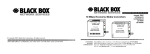
Black Box Modular Switches
Installation and User Guide (8/99)
April 1999
LE14XXA
Modular Switches
Customer
Support
Information
Call our Technical Support Specialists to discuss your application.
For 24-hour technical support: Call (724) 746-5500 or Fax: (724) 746-0746
To order: Call (724) 746-5500 7:00 A.M. to 8:00 P.M. EST
Mail order: Black Box Corporation. 1000 Park Drive, Lawrence, PA 15055
i
Black Box Modular Switches
Installation and User Guide (8/99)
Black Box
Modular Switches
Installation and User Guide
Trademarks
UL is a registered trademark of Underwriters Laboratories
Important: The LE14XXA Modular Switches contain no user-serviceable parts. Attempted
service by unauthorized personnel shall render any and all warranties null and void. If
problems are experienced with an LE14XXA, consult Section 6, Troubleshooting, of this User
Guide.
1999 Black Box Corporation
Printed in the United States of America.
______________________________________________________
Contacting Black Box Corporation
Please use the mailing address and phone and fax numbers listed below:
Black Box Corporation
1000 Park Drive
Lawrence, PA 15055
Phone: (724) 746-5500
Fax:
(724) 746-0746
P/N 84-00020 (Rev A 08/99)
ii
Black Box Modular Switches
Installation and User Guide (8/99)
FCC STATEMENT
FEDERAL COMMUNICATIONS COMMISSION
AND
CANADIAN DEPARTMENT OF COMMUNICATIONS
RADIO FREQUENCY INTERFERENCE STATEMENTS
This equipment generates, uses, and can radiate radio frequency energy and if not
installed and used properly, that is, in strict accordance with the manufacturer’s
instructions, may cause interference to radio communication. It has been tested and
found to comply with the limits for a Class A computing device in accordance with
the specifications in Subpart J of Part 15 of FCC rules, which are designed to provide
reasonable protection against such interference when the equipment is operated in a
commercial environment. Operation of this equipment in a residential area is likely to
cause interference, in which case the user at his own expense will be required to take
whatever measures may be necessary to correct the interference.
Changes or modifications not expressly approved by the party responsible for
compliance could void the user’s authority to operate the equipment.
This digital apparatus does not exceed the Class A limits for radio noise emission
from digital apparatus set out in the Radio Interference Regulation of the Canadian
Department of Communications.
Le présent appareil numérique n’émet pas de bruits radioélectriques dépassant les
limites applicables aux appareils numériques de classe A prescrites dans le
Règlement sur le brouillage radioélectrique publé par le ministère des
Communications du Canada.
iii
Black Box Modular Switches
Installation and User Guide (8/99)
NORMAS OFICIALES MEXICANAS (NOM)
ELECTRICAL SAFETY STATEMENT
INSTRUCCIONES DE SEGURIDAD
1.
Todas las instrucciones de seguridad y operación deberán ser leídas antes de que el
aparato eléctrico sea operado.
2.
Las instrucciones de seguridad y operación deberan ser guardadas para referencia futura.
3. Todas las advertencias en el aparato eléctrico y en sus instrucciones de operación deben
ser respetadas.
4. Todas las instrucciones de operación y uso deben ser seguidas.
5. El aparato eléctrico no deberá ser usado cerca del agua—por ejemplo, cerca de la tina de
baño, lavabo, sótano mojado o cerca de una alberca, etc..
6. El aparato eléctrico debe ser usado únicamente con carritos o pedestales que sean
reconnendados por el fabricante.
7. El aparato eléctrico debe ser montado a la pared o al techo sólo como sea recommendado
por el fabricante.
8. Servicio—El usuario no debe intentar dar sercicio al equipo eléctrico más allá a lo descrito
en las instrucciones de operatión. Todo otro servicio deberá ser referido a personal de
servicio calificado.
9. El aparato eléctrico debe ser situado de tal mannera que su posición no interfiera su uso.
La colocación del aparato eléctrico sobre una cama, sofá, alfombra o superficie similar
puede bloquea la ventilación, no se debe colocar en libreros o gabinetes que impidan el
flujo de aire por los orificios de ventilación.
10. El equipo eléctrico deber ser situado fuera del alcance du fuentes de calor como radiadores,
registros de calor, estufas u otros aparatos (incluyendo amplificadores) que producen
calor.
11. El aparato eléctrico deberá ser connectado una fuente de poder sólo del tipo descrito en el
instrucivo de operación, o como se indique en el aparato.
12. Precaución debe ser tomada de mal manera que la tierra fisica y la polarización del equipo
no sea eliminada.
13. Los cables de la fuente de poder deben ser guiados de tal manera que no sean pisados ni
pellizcados por objetos colocados sobre o contra ellos, poniendo particular atención a los
contactos y receptáculos donde salen del aparato.
14. El equipo eléctrico debe ser limpiado únicamente de acuerdo a las recommendaciones del
fabricante.
15. En caso de existir, una antena externa deberá ser localizada lejos de las lineas de energia.
16. El cable de corriente deberá ser desconectado del cuando el equipo no sea usado por un
largo periodo de tiempo.
17. Cuidado debe ser tomado de tal manera que objectos liquidos no sean derramados sobre la
cubierta u orificios de ventilación.
18. Servicio por personal calificado deberá ser provisto cuando:
A:
El cable de poder o el contacto ha sido dañado; u
B:
Objectos han caído o líquido ha sido derramado dentro del aparato; o
C:
El aparato ha sido expuesto a la lluvia; o
D:
El aparato parece no operar normalmente o muestra un cambio en su
desempeño; o
E:
El aparato ha sido tirado o su cubierta ha sido dañada.
iv
Black Box Modular Switches
TABLE OF CONTENTS
Installation and User Guide (8/99)
PAGE
1. SPECIFICATIONS.........................................................................................................1
1.1 Technical Specifications........................................................................................1
1.2 Model Information................................................................................................4
2. INTRODUCTION ..........................................................................................................5
2.1 Inspecting the Package and Product ......................................................................5
2.2 Product Description - Black Box Modular Switches ...........................................6
2.2.1 Modular Switch chassis models ................................................................5
2.2.2 4-port modules, 100Mb fiber ...................................................................7
2.2.3 4-port module, 10 Mb fiber ......................................................................7
2.2.4 4-port module, RJ-45 (copper) ................................................................8
2.2.5 4-port modules, “3 + 1” , 3@RJ-45 and 1@fiber .....................................8
2.2.6 Frame Buffering and Latency ....................................................................9
2.3 Features and Benefits..........................................................................................11
2.4 Applications........................................................................................................12
3. INSTALLATION.........................................................................................................15
3.1 Locating the LE14XXA-Series Switches ............................................................15
3.2 Connecting Ethernet Media.................................................................................16
3.2.1 Connecting Fiber Optic ST-type “twist-lock” .........................................16
3.2.2 Connecting Fiber Optic SC-type “snap -in”..............................................17
3.2.3 Connecting Fiber Optic Single-Mode........................................................17
3.2.4 Connecting Twisted- Pair, RJ-45..............................................................17
3.3 Table-top or shelf mounting................................................................................18
3.3.1 Wall (or Vertical) Mounting..................................................................18
3.3.2 Rack-Mounting .....................................................................................18
3.4 Copper ports, Inernal jumper settings for 10/100Mbps ...................................19
3.5 Fiber ports, Internal Jumper settings for 100Mbps ..........................................20
3.6 Combo ports, Internal Jumper settings for RJ-45 & fiber 10 or 100Mbps .......21
3.7 Fiber ports, Internal Jumper settings for 10Mbps ............................................22
3.8 Powering the LE14XXA-Series Switches ...........................................................23
3.9 4-port Module (4PM) Installation......................................................................24
3.9.1 Preparation for installing, changing and removing 4PMs......................24
3.9.2 Installing 4PM cards in the LE14XXA-Series chassis..........................26
3.9.3 Removing 4PM cards in the LE14XXA-Series chassis ........................27
4. OPERATION................................................................................................................29
4.1 Switching Funtionality........................................................................................29
4.2 Status LEDs ........................................................................................................30
4.3 Manual switches for Up-link and Full/Half Duplex...........................................30
4.4 Auto-negotiation option for copper Fast Ethernet ports ..................................30
4.5 Auto-negotiation option for 10 Mbps ports HDX/FDX mode ........................32
4.6 Collision based flow control................................................................................32
4.7 Power budget Calculation for LE14XXA-Series 4PM’s Fiber media ................33
5. 4-PORT MODULES (AS SEPARATE ITEMS IN A SHIPMENT)................................34
5.1 Inspecting the Package and Product ...................................................................34
v
Black Box Modular Switches
Installation and User Guide (8/99)
5.2 Product Description ...........................................................................................34
5.2.1 LE1428C, 100Mb multi-mode FX-ST, “twist lock” connector ...............35
5.2.1a LE1424C, 10 Mb multi-mode FL-ST, “twist-lock” connector...............35
5.2.2 LE1419C, 100Mb multi-mode FX-SC, “snap-in” connector. .................36
5.2.3 LE1421C, 100Mb single-mode FX-SC, “snap-in” connector...................36
5.2.4 LE1422C, 100Mb FX Small-Form-Factor “plug-in” connector...............37
5.2.5 LE11423C, 100Mb FX Small-Form-Factor “plug-in” connector.............37
5.2.6 LE1425C, 10/100Mbps (RJ-45 for standard twisted-pair)......................38
5.2.7 LE1426C, “3TP+1F” Combo (Twisted Pair and 100Mb Fiber SC mm) .39
5.2.8 LE1427C, “3TP+1F” Combo (Twisted Pair and 100Mb Fiber ST mm) .39
5.2.9 LE1429C, “3TP+1F” Combo (Twisted Pair and 100Mb Fiber SC sglm)40
5.2.10 4PM -FP (Face Plate) ..............................................................................40
6.0 TROUBLESHOOTING.....................................................................................41
6.1 Before Calling for Assistance..............................................................................41
6.2 When Calling for Assistance ...............................................................................41
6.3 Shipping and Packaging Information...................................................................42
vi
Black Box Modular Switch
1.
SPECIFICATIONS
1.1
Technical Specifications
Installation and User Guide (08/99)
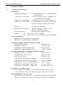
Performance
Aggregate Filtering Rate:
2,380,800 frames/sec for 16 100Mbps ports
(for LE1416A)
(all ports are wire speed)
1,190,400 frames/sec for 8 100Mbps ports
(for LE1401A & LE1408A)
Aggregate Forwarding Rate: (for Modular Switch Fast Ethernet ports)
(all ports are wire speed)
1,190,400 frames per second, 16-port units
595,200 frames per second, 8-port units
Data Rate:
Address Table Capacity:
10 Mbps and 100Mbps
24K node addresses (12K on 8-port
models), with address aging
Packet buffer Size :
8 MB dynamic (4MB for 8-port)
Latency:
5 µs + packet time (100 to 100Mbps)
15 µs + packet time (10 to 10 Mbps, and 10 to 100Mbps)
Network Standards
Ethernet V1.0/V2.0 IEEE 802.3: 10BASE-T,
IEEE 802.3u: 100BASE-TX, 100BASE-FX
Maximum 10 Mbps Ethernet Segment Lengths
Unshielded twisted pair
Shielded twisted pair
10BASE-FL multi-mode fiber optic
10BASE-FL single-mode fiber optic
-
100 m (328 ft)
150 m (492 ft)
2 km (6,562 ft)
10 km (32,810 ft)
Maximum Standard Fast Ethernet Segment Lengths:
10BASE-T (CAT 3, 4, 5 UTP)
- 100 m (328 ft)
100BASE-TX (CAT 5 UTP)
- 100 m (328 ft)
Shielded twisted pair
- 150 m (492 ft)
100BASE-FX, half-duplex, multi-mode
100BASE-FX, full-duplex, multi-mode
100BASE-SX, short wavelength HDX m.m.
100BASE-FX, half-duplex, single-mode
100BASE-FX, full-duplex, single-mode
- 412 m (1350 ft)
- 2.0 km (6,562 ft)
- 300 m ( 935 ft)
- 412 m (1350 ft)
- 15.0 km (49,215 ft)
Connectors for copper wiring
Twisted Pair at 10/100Mb: RJ-45 shielded, female, front mounted
(for LE14XXA-Series Fast Ethernet copper ports, use Cat 5 cable)
Fiber Multi-mode connector types:
Fiber Port, SC-type (snap -in):
Fiber optic multi-mode, 100BASE-FX
Fiber Port, ST-type (twist-lock): Fiber optic multi-mode, 100BASE-FX
1
Black Box Modular Switches
Installation and User Guide (8/99)
Fiber Port, MTRJ-type (plug-in):Fiber optic multi-mode, 100BASE-FX
Fiber Port, VF-45 type (plug-in): Fiber optic multi-mode, 100BASE-FX
Fiber Port, ST-type (twist-lock): Fiber optic multi-mode, 10ASE-FL
Fiber Single-mode connector types:
Fiber Port, SC-type:
Fiber optic single-mode, 100BASE-FX
Manual switch-selections and jumpers
Up-link Push-button: Crossover sw for one RJ-45 port per LE1425C
Fiber default: Full-duplex (Internal jumpers may select HDX mode)
Copper default: Auto-negotiation (Internal jumpers may alternatively
select fixed 100Mb full-duplex, or fixed 100Mbps half-duplex)
LEDs: Per Port
LK: Steady ON when media link is operational
ACT: ON with receiver port activity
FDX/HDX: ON = Full-Duplex Mode
OFF = Half-Duplex Mode
100/10: ON = 100Mbps speed
OFF = 10 Mbps
Operating Environment
Ambient Temperature: 32° to 120° F (0° to 50°C)
Storage Temperature: -5°to 140°F (-20°to 60°C)
Ambient Relative Humidity: 10% to 95% (non-condensing)
Packaging
Enclosure:Rugged High strength metal. Suitable for stand-alone or rack-mounting
Dimensions: 1.75 in H x 17.0 in W x 9.0 in D (9.0 in W for QS580)
4.45cm H x 43.2cm W x 22.9cm D (22.5 cm W for QS580)
Weight:
4.0 lb. (1.8 Kg) for rack-mount models, 2.5 lb. for table-top
Cooling method: Fan cooled, @ 9 cfm
Power Supply (Internal)
AC Power Connector: IEC-type, male recessed, rear of chassis, with adjacent
manual ON-OFF switch (on AC model only)
Input Voltage:
110 to 240 VAC (auto-ranging)
Input Frequency: 47 to 63 Hz (auto-ranging)
Power Consumption: 20 watts typical (8 port model)
35 watts typical (16 port model)
Redundant power supplies available as options
48VDC Power Supply (Optional)
Power Input Voltage : 36 to 70 VDC (auto ranging)
Terminal Block in rear: “-, GND, +”
Power Consumption: same as for AC models, see above
2
Black Box Modular Switches
Installation and User Guide (8/99)
For Dual Source and Redundant DC supply options, see Appendices
For optional 23” Telco rack-mount brackets, order Model # RMB-23W
Agency Approvals
UL listed (UL1950), cUL, CE
Emissions meet FCC Part 15 Class A
Warranty
Three years, return to factory
3
Made in USA
Black Box Modular Switches
1.2
Installation and User Guide (8/99)
Model Information
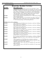
Black Box Modular Switches
MODEL
DESCRIPTION
LE1401A
8-port 10/100 Switch, holds up to two 4-port Modules with 4
switched ports each. Shelf or table-top mounting. For mixed-media
flexibility, combinations of RJ-45 and various fiber port connector
types, modes, and speeds can be configured. Full speed filtering
and forwarding at 100Mbps speed across all ports, self-learning
12K-node address table, and large 4MB packet buffers. Frontmounted LEDs, internal auto-ranging power supply
Same as Model LE1401A Switch, but in a 19” rack-mount package,
with mounting brackets.
Same as Model LE1408A, but with 24K-node address table and
8MB packet buffers. Holds up to four 4-port Modules (4PMs),
19” rack-mount package, with mounting brackets.
LE1408A
LE1416A
LE14XXA-Series 4Port Modules
LE1419C
Fiber module for LE14XXA-Series Switches, with four 100Mbps
multi-mode FX SC connectors
LE1428C
Fiber module for LE14XXA-Series Switches, with four 100Mbps
multi-mode FX ST connectors
LE1421C
Fiber module for LE14XXA-Series Switches, with four 100Mbps
single-mode FX SC connectors
LE1422C
Fiber module for LE14XXA-Series Switches, with four 100Mbps
multi-mode FX “MTRJ” connectors
LE1423C
Fiber module for LE14XXA-Series Switches, with four 100Mbps
multi-mode FX “VF-45” connectors
LE1424C
Fiber module for LE14XXA-Series Switches, with four 10 Mbps
multi-mode FL ST-type connectors
LE1425C
RJ-45 module for LE14XXA-Series Switches, with four 100Mbps
auto-negotiating RJ-45 ports, one of which has an up-link pushbutton
LE1426C
3TP+1F module for LE14XXA-Series Switches, with three
10/100MB auto-negotiating RJ-45 ports and one fiber port with
100Mbps multi-mode FX SC connector
LE1427C
3TP+1F module, same as LE1426C but with fiber ST-type multimode connector
LE1429C
3TP+1F module, same as LE1426C but with fiber SC-type singlemode connector
4
Black Box Modular Switches
Installation and User Guide (8/99)
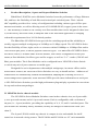
2.
Introduction
2.1
Inspecting the Package and Product
Examine the shipping container for obvious damage prior to installing this product;
notify the carrier of any damage which you believe occurred during shipment or delivery.
Inspect the contents of this package for any signs of damage and ensure that the items listed
below are included.
This package should contain:
1
LE1401A, LE1408A, LE1416A Modular Switches
1
AC Power Cord (U.S. and other 115 VAC only)
1
Set of two wall-mounting brackets (for LE1401A Model only)
1
Set of metal “Ears” for optional “19” rack mounting (for LE1408A & LE1416A
only)
1
Installation and User Guide (this manual),
Remove the items from the shipping container. Be sure to keep the shipping container
should you need to re-ship the unit at a later date.
In the event there are items missing or damaged, contact Black Box. If the unit needs to
be returned, please use the original shipping container if possible. Refer to Section 6,
Troubleshooting, for specific return procedures.
5
Black Box Modular Switches
2.2
Installation and User Guide (8/99)
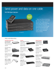
Product Description , 8-port and 16-port Modular Switches
Black Box LE14XXA series Modular Switches boost the performance of large Ethernet
LANs, and have the flexibility of both fiber and twisted-pair switched ports. Their “mixedmedia” capability provides for a variety of configurations including various types of fiber port
connectors and modes, as well as allowing a mix of 10/100Mb RJ-45 (copper) ports in the same
unit. This flexibility is achieved via a family of 4-Port modules that can be integrated with a base
unit, in the factory and in the field, to adapt the unit to the individual application’s changing
mixed-media requirements for a 10/100 Switch product.
The Black Box LE14XXA-Series provide the switching speed and the reliability to
moothly support multiple workgroups at 100Mbps or 10 Mbps speed. The LE14XXA-Series
offers the flexibility of four, eight, twelve or sixteen switched 100Mbps or 10 Mbps fiber and/or
10/100 twisted pair ports, in all the popular connector types. The Black Box LE14XXA-Series
offers the LE1401A, LE1404A and LE1416A models, each with a configuration of four port
modules (4-Port Modules) for fiber types and for copper, as well as “3+1” combo (3 RJ-45 and
1 fiber) port modules. The 4-Port Modules can be configured into a LE14XXA-Series Switch
base unit in any mix of port connector or media types.
Designed for use in departments with multiple workgroups, in remote offices and in
network traffic centers, the LE14XXA-Series Switches are easy to install and use. Addresses of
attached nodes are automatically learned and maintained, adapting the switching services to
network changes and expansions. Front-mounted LEDs provide status information on each port.
The LE14XXA-Series Switches provide high performance plug-and-play operation in convenient
table-top and rack-mount packages.
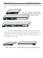
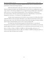
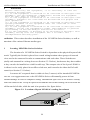
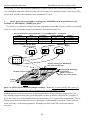
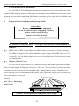
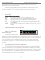
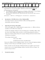
2.2.1 LE14XXA-Series chassis models
The LE14XXA-Series Modular Switches come in three chassis sizes, an 8-port tabletop, an 8-port rack-mount, and a 16-port rack-mount. Each is configurable with a selection of
quad-port (i.e., 4-port) modules, providing the capability of 4, 8, 12, and 16 switched ports. The
port modules are normally factory installed, but may be changed or added in the field. (See
Section 5)
The 8-port LE1401A table-top chassis is compact in size and suitable for shelfmounted use in network wiring centers. The LE1408A and LE1416A are 19” rack-mountable
6
Black Box Modular Switches
Installation and User Guide (8/99)
Switches with two or four 4-port slots in the front, i.e., with a capacity of 8 or 16 switched
ports. The LE1408A and LE1416A rack-mount units are typically used in larger network wiring
PWR
Black
Black Box
Box LE1401A
LE1401A
ModularSwitches
ACT
FDX/HDX
LK
1
2
3
4
1
2 Switch 3
Fiber
4
x
centers.
LK
1
2
3
Figure 2.2.1a: Front view, 8-port LE1401A
4
ACT
100/10
FDX/HDX
table-top, 8-port LE1408A and 16-port LE1416A
8 Ports Table-Top
Modular Switches
Black Box LE1408A PWR
Modular
Switch
Fiber
Switch
FDX/HDXLK
1
2
3
4
1
2
3
ACT
4
ACT
LK
1
FDX/HDX
2
3
4
ACT
FDX/HDX
100/10
Magnum
Black BoxQS5116
QS5116
LE1416A PWR
Magnum
Modular Switch
Fiber Switch
FDX/HDX
1
2
3
4
LK
1
2
3
4
ACT
ACT
GARRETT
GARRETT
FDX/HDX
1
2
3
4
LK
1
2
3
4
x
8-Port Rack Mount
LK
100/10
1
2
3
4
ACT FDX/HDX 1
LK
FDX/HDX
1
2
3
4
2
3
4
ACT
16-Port Rack Mount
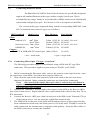
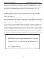
Mixed-media combination modules (4-port modules with three fiber ports and one
twisted-pair port) are supported in all of the LE14XXA-Series Fiber Switch models. All 4Portmodule manual-selection switches and LED’s are located on the front panel, with the IEC
standard AC power connector (and a manual ON - OFF power switch) located at the rear. Fan
driven cooling air flows left to right.
110-220
VAC
47-63Hz
1.0-0.5A
ON
110-220
VAC
47-63Hz
1.0-0.5A
ON
OFF
OFF
Figure 2.2.1b: Rear view - Black Box table-top & rack-mount 4-Series Switches
7
Black Box Modular Switches
Installation and User Guide (8/99)
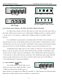
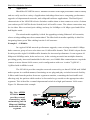
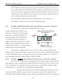
2.2.2 4-port modules, 100Mb fiber
FDX/HDX
1
2
3
LK
4
ACT
FDX/HDX
1
2
3
4
1
2
3
4
1
2
3
LK
1
2
3
4
2
3
4
ACT
VF45-Small Form Factor
ST-Type
FDX/HDX
1
LK
FDX/HDX 1
LK
2
3
4
1
2
3
4
4
ACT
ACT
MTRJ-Small Form Factor
SC-Type
Fig.2.2.2 Fiber 4-Port Modules, LE1420C, LE1419C LE1423C LE1422C
In a fiber 4-port module, all of the fiber ports are of the same speed, the same multi- or
single-mode, and the same connector type. Multi-mode 100Mbps models are available with ST,
SC, MTRJ, and VF-45 connectors. Single-mode 100Mbps models are available with SC
connectors.
The 100Mb fiber 4-port modules on the Black Box LE14XXA-Series normally are set
(factory default) to operate in full-duplex mode for best fiber distance and performance. On the
LE14XXA-Series, the user may select full- or half-duplex mode per-port with an internal jumper
setting (See Section 3.4) for the flexibility to adapt to any type of Fast Ethernet devices.
On Black Box fiber 4PMs, there are three LED’s per fiber port. The Link (LK) LED
indicates “ready for operation” when lit, another LED indicates operation in full-duplex mode
when ON (when it is OFF, operation is half-duplex), and an LED indicates Receiving Activity
(ACT) on the port. A fiber cable must be connected to each 100Mb port and a proper link (LK
it) must be made with the device at the other end of the cable in order for the LK LEDs to
provide valid indications of operating conditions.
FDX/HDX
2.2.3 4-port modules, 10 Mb fiber
The 10 Mb model LE1424C fiber 4-port
module is the same as the 100Mb LE1428C, except
1
2
LK
3
4
ACT
1
2
3
4
for 10Mb speed rather than 100Mb speed. It
ST-Type
supports distances according to the 10Base-FL standard, i.e., 2Km distance for multi-mode fiber.
(Single-mode for 10km distance may be available as a special order).
8
Black Box Modular Switches
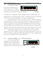
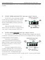
2.2.4
Installation and User Guide (8/99)
4-Port Module, RJ-45 (copper)
The Black Box LE14XXA-
LK
1
2
3
4
ACT
LE1425C, provides four 10/100Mb
x
Series copper port module, model
100/10
FDX/HDX
switched. RJ-45 ports. The 10/100Mb
switched ports are independently N-way auto-negotiating
LE1425C
for operation at 10 or 100Mb speed in full- or half-duplex mode (as a default setting). They
independently move to half-duplex mode at 10 Mb or at 100Mb speed if the device at the other
end of the twisted pair cable is half-duplex or is not an auto-negotiating device.
On the model LE1425C , there are four LED’s for each port. The LK (Link) indicates
“ready for operation” when lit, the ACT (Activity) indicates receiving activity on that port, the
10/100 LED indicates operation at 100Mb speed when ON and at 10 Mb speed when OFF
(when auto-negotiation is not disabled), and the FDX/HDX LED is ON to indicate full-duplex
operation and OFF, to indicate half-duplex mode. A twisted pair cable must be connected into
each RJ-45 10/100Mb port and a proper link (LK lit) must be made with the device at the other
end of the cable in order for the LEDs to provide valid indications of operating conditions.
Internal jumper settings (See Section 3.4) allow technicians to over-ride the autonegotiation feature and to manually set each port at full-duplex or half-duplex. One port on each
RJ-45 4-port module is equipped with a Media Dependent Interface-Crossover (MDI-X) push
button switch to simplify cascaded or up-link connections.
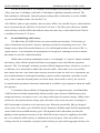
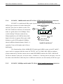
2.2.5
Combo 4 Port Modules, “3 + 1”, 3 RJ-45 and 1 fiber port
The combo 4-port modules are
LK
1
2
3
4
ACT
combination of copper and fiber media,
FDX/HDX
available as three 10/100 switched RJ-45
FDX/HDX
100/10
copper ports and one 100Mb switched
multi-mode fiber ST or SC port or single-mode SC port.
LE1426C
9
Black Box Modular Switches
Installation and User Guide (8/99)
The RJ-45 ports run at 10/100Mbps with N-way auto-negotiation capability, whereas
the fiber port runs at 100Mbps with half- or full-duplex capability manually selected. The
default condition is full-duplex. Internal jumpers settings allow technicians to set the 100Mb
fiber port to half-duplex mode. (See Section 3.4).
On LE14XXA Combo 4-port modules, there are three LED’s for each RJ-45 port, which indicate
status as described for the LE1426C in Section 2.2.4 above. The fiber port will run at 100Mbs
speed at all times, and has LEDs that indicate status the same way as described for the Fiber 4port modules in Section 2.2.2 above.
2.2.6
Frame Buffering and Latency
The Black Box LE14XXA-Series are store-and-forward switches. Each frame (or
packet) is loaded into the Switch’s memory and inspected before forwarding can occur. This
technique ensures that all forwarded frames are of a valid length and have the correct CRC, i.e.,
are good packets. This eliminates the propagation of bad packets, enabling all of the available
bandwidth to be used for valid information.
While other switching technologies such as "cut-through" or "express" impose minimal
frame latency, they will also permit bad frames to propagate out to the Ethernet segments
connected. The "cut-through" technique permits collision fragment frames, which are a result of
late collisions, to be forwarded to add to the network traffic. Since there is no way to filter
frames with a bad CRC (the entire frame must be present in order for CRC to be calculated), the
result of indiscriminate cut-through forwarding is greater traffic congestion, especially at peak
activity. Since collisions and bad packets are more likely when traffic is heavy, the result of
store-and-forward operation is that more bandwidth is available for good packets when the traffic
load is greatest.
To minimize the possibility of dropping frames on congested ports, each Black-Box
LE14XXA-Series Switches dynamically allocates buffer space from an 8 MB memory pool,
ensuring that heavily used ports receive very large buffer space for packet storage. (Many other
switches have their packet buffer storage space divided evenly across all ports, resulting in a
small, fixed number of packets to be stored per port. When the port buffer fills up, dropped
packets result.) The other two LE14XXA-Series Switches LE1408A and LE1416A dynamically
allocates buffer from an 4MB memory pool. This dynamic buffer allocation provides the
capability for the maximum resources of the LE14XXA-Series unit to be applied to all traffic
loads, even when the traffic activity is unbalanced across the ports. Since the traffic on an
operating network is constantly varying in packet density per port and in aggregate density, the
10
Black Box Modular Switches
Installation and User Guide (8/99)
LE14XXA-Series Switches are constantly adapting internally to provide maximum network
performance with the least dropped packets.
When the Switch detects that its free buffer queue space is low, the Switch sends
industry standard (full-duplex only) PAUSE packets out to the devices sending packets to cause
“flow control”. This tells the sending devices to temporarily stop sending traffic, which allows a
traffic catch-up to occur without dropping packets. Then, normal packet buffering and
processing resumes. This flow-control sequence occurs in a small fraction of a second and is
transparent to an observer. See Section 4.6 for additional details.
Another feature implemented in LE14XXA--Series Switches is a collision-based flow
control mechanism (when operating at half-duplex only). When the Switch detects that its free
buffer queue space is low, the Switch prevents more frames from entering by forcing a collision
signal on all receiving half-duplex ports in order to stop incoming traffic.
The latency (the time the frame spends in the Switch before it is sent along or
forwarded to its destination) of the LE14XXA-Series Switches varies with the port-speed types,
and the length of the frame is a variable here as it is with all store-and-forward switches. For 10
Mb-to-10 Mb or 10 Mb-to-100Mb or 100Mb-to-10 Mb forwarding, the latency is 15
microseconds plus the packet time at 10 Mb. For 100Mb-to-100Mb forwarding, the latency is 5
microseconds plus the packet time at 100Mb.
11
Black Box Modular Switches
2.3
Installation and User Guide (8/99)
Features and Benefits
n
100Mb switching services for large, high performance Ethernet LANs
LE14XXA-Series Switches provide Fast Ethernet switching on all ports. They
perform high speed filter/forward operations on the traffic, giving each port’s
segment a full 100Mb (or 10 Mb) of bandwidth.
n
Configurable with fiber ports, all connector types and speeds
4-port modules are available with 100Mb mm ST, SC, VF-45, MTRJ single-mode
SC, and 10 Mb ST-type connectors. The configuration of the fiber ports, in the
factory or in the field, allows the LE14XXA-Series Switches to adapt to mixed
and changing fiber types in any application.
n
Configurable with RJ-45 (copper) ports, 10/100 auto-negotiation
RJ-45 4-port modules provide twisted pair segment connections, with N-way
auto-negotiation or with manual speed and mode settings per port
n
Mixed-media configurations for maximum flexibility
Combinations of port module types can be configured in the same unit, adapting
the LE14XXA-Series Switches to varying quantities and types of fiber vs. copper
media. Port module changes can even be done in the field.
n
Full-duplex or Half-duplex operation, auto-sensing
All fiber and RJ-45 (copper) ports are capable of half- or full-duplex, individually
selected. All RJ-45 ports support 10/100 auto-negotiation, or can be user-selected
for the desired operating mode and speed.
n
16-port, 12-port, 8-port and 4-port models
With two chassis sizes (16-port and 8-port) configurable with 4-port 4PMs,
capacity options complement the mixed-media configurability.
n
Plug-and-Play installation for high performance switching
Black Box LE14XXA-Series Switches are self-learning for node addresses.
They can be placed into operation without complex set-up procedures, even in
large networks. They operate transparent to system software.
n
Front-mounted LEDs, world-wide AC power supply
Front panel LED’s on each 4-port module display the status of each
port for easy monitoring. An internal auto-ranging AC power supply
allows LE14XXA Series Switches to be used throughout the world. (A 48VDC
power supply is optional, see Appendix B).
12
Black Box Modular Switches
.2.4
Installation and User Guide (8/99)
Applications
Black Box LE14XXA-Series Modular Switches offer high performance and flexibility,
and are easily used in a variety of applications including client/server computing, performance
upgrades of departmental networks, and collapsed backbone applications. The Dual-Speed
characteristic of the LE14XXA-Series Switches enables them to inter-connect a series of subnets
(one subnet per LE14XXA-Series Switch) in a LAN traffic center. The subnet connections may
be via either fiber or twisted pair cabling, and may be 100Mbps or 10 Mbps speed and full-or
half-duplex mode.
The mixed-media capability is ideal for upgrading existing Ethernet LAN networks,
where existing cabling must be accommodated. The fiber-built-in media capability is ideal for
integrating future-proof fiber cabling into the LAN structure.
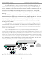
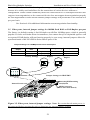
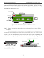
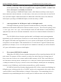
Example 1 : LE1401A
In a typical 10 Mb network performance upgrade, some existing cascaded 10 Mbps
hubs connect a group of users who share one 10 Mb traffic domain. The LE1401A 4port Series
Switch provides eight 10/100Mb traffic domains for increased performance. It can segment 10
Mbps and 100Mbps units, hubs and servers, in the existing network into multiple domains,
providing greatly increased bandwidth. In this case, two 100Mb fiber connections are required to
connect to more distant LAN centers, and a configuration with two “combo” 3@RJ-45 +
1@fiber-built-in 4PMs is used.
The LE1401A provides complete network connectivity so that all 10 Mb and 100Mb
nodes operate in a unified manner, functioning as one plug-and-play switched network facility.
It filters and forwards packets from one segment to another, containing the local traffic and
allowing only the packets which need to be forwarded to go outside to the appropriate other
segments. This is ideal for a central departmental switch in a high-performance LAN center.
Figure 2.4 illustrates this example.
Fig. 2.4a: AFTER
LE1401A Switch
provides central
connectivi ty while
maintaining full 10
Mbps and 100Mbps
bandwidth on each
segment.
Black Box LE1416A P W R LK
Modular Switch
100/10
100Mbps Fiber
Segment
Magnum800E
Workgroup Hub PWR COL
100Mb/s
GARRETT
1
4
2
3
LINK
RX
ACT
FDX/HDX
LK
100/10
ACT
FDX/HDX
100Mbps Fiber
Segment
5
8
6
7
LINK
RX
Magnum800E
Workgroup Hub
100Mb/s
GARRETT
PWR COL
1
4
2
3
LINK
RX
10 Mbps users
100Mbps users
13
5
8
6
7
LINK
RX
Black Box Modular Switches
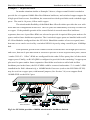
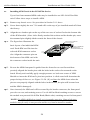
Example 2 : 8-port LE1408A
Installation and User Guide (8/99)
In another application, a Switch is needed to provide a Fast Ethernet backbone. The
backbone consists of four high-speed LAN segments, each operating over 100MB full-duplex
fiber lines. In addition to interconnecting the fiber backbone segments in the network center, the
Switch needs to provide high-speed switched support for two central servers, for a 100MB
connection to a router, and for a dual-speed hub serving a local workgroup of over a dozen users,
printers, etc.
The LE1408A equipped with one Fiber and one RJ-45 4-port modules provides an
economical solution, configured with 8 switched ports (four 100Mbps fiber and four 10/100 RJ45) in a rack-mount box. No Media Converters are needed. The Fiber 4PM can be selected to
provide any 100Mbps fiber media connector type desired. 4PMs with multi-mode or singlemode fiber types are available.
This requirement for connecting local devices over twisted pair cabling is handled by
the LE1408A using a RJ-45 4-Port Module. The 4PM provides a switched port for two local
high speed servers, another for the router, another for the users connecting into a 16-port dualspeed hub such as the LE1408A.
Since 100Mb fiber Ethernet has severe distance limitations at half-duplex, it is
necessary in high speed backbones to operate fiber links in the full-duplex mode. Many low-end
switches that only have RJ-45 N-way 10/100Mb ports would need to have a media converter on
each fiber line. But most media converters do not support auto-negotiation and would not enable
the fiber backbone lines to operate full-duplex. But the LE1408A . . . with built-in switched fiber
ports at 100Mb speed, with full-duplex mode as a default setting on fiber ports, and with some
RJ-45 N-way 10/100Mb ports as well. . . handles this application readily.
PWR
100/10
Magnum
QS5116
Black0Box
le1408a
1
Fiber
Modular
Switch
Switch
2
3
4
GARRETT
LK
ACT
ACT
FDX/HDX
L K
100/10
FDX/HDX
Internet
Magnum DS8016 Stackable Hub
PWR
X
BR
COL 10
COL 100
LK/RX
PORT1 2 3 4 5
100
1
12
6 7 8 9 10 11 12 13 14 15 16
2
13
3
14
4
15
5
6
7
8
9
10
11
16
UPLINK
Router
100Mb Fiber Link
segment
100Mb Servers
Magnum 800E
WorkgroupHub
100Mb/s
GARRETT
PWRCOL
1
4
2
3
LINK
R
X
5
8
6
7
LINK
R X
Figure 2.4b: The LE1408A provides a 100Mb fiber backbone facility.
14
Black Box Modular Switches
Installation and User Guide (8/99)
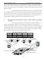
Example 3 : 16-port LE1416A
In another situation similar to Example 2 above, a larger central Switch is needed to
provide for a 6-segment 100Mb fiber Fast Ethernet backbone, and switched copper support for
4 high speed local servers. In addition, the router and two dual-speed hubs need switched copper
ports. The total is 14 ports, 6 fiber and 8 copper.
The mixed-media flexibility of the Black-Box 4-Port Switches provides the user with
more than one configuration in this case. The two ports not immediately used may be either fiber
or copper. If the probable growth of the central Switch is towards more fiber backbone
segments, then two 4-port fiber 4PMs are selected to provide 6 required fiber ports and two for
spares and/or future backbone expansion. The 8 switched copper ports are handled with two RJ
45 4-Port Modules configured into the LE1416A. Should the number of servers expand, more
than one server can be serviced by a switched LE1416A port by using a small 4-port 100Mbps
hub.
If the probable growth of the central Switch is towards more local high speed servers
and users, then one 4-port fiber 4PM is selected to provide 4 of the required fiber ports, and two
“combo 3 RJ-45 + 1 fiber” 4PMs are configured for the other 2 fiber ports plus 6 of the switched
copper ports. Finally, an RJ-45 QPM is configured to provide for the remaining 2 copper ports
plus two for spares and/or future expansion. Should the need arise to add a built-in-fiber
backbone port in the future, the RJ-45 4PM could be removed and another “3+1 combo” 4PM
installed in the field. Alternatively, a 100MB Media Converter (such as the LH1500A-ST-R2)
may be used on a copper port, with internal jumpers (See Section 3.4) set to support fixed
100MB FDX on the RJ-45 port.
PWR
Magnum
MagnumQS5116
QS5116
Black-Boxle1416a
Fiber Switch
Modular
Switch
GARRETT
100/10
1
2
3
4
FDX/HDX
100/10
LK
ACT
ACT
1
2
3
4
FDX/HDX
LK
LK
ACT
LK
ACT
ACT
100/10
10/100
FDX/HDX
100/10
10/100
FDX/HDX
Internet
Router
100Mb fiber segment
Magnum DS8016 Stackable
X Hub1
2
PWR BR
COL 10
COL 100
Magnum DS8016 Stackable
X Hub1
2
PWR BR
COL 10
COL 100
LK/RX
P O R T1 2 3 4 5
100
12
6 7 8 9 10 11 12 13 14 15 16
13
3
14
4
15
5
6
7
8
9
10
LK/RX
12
P O R 1T 2 3 4 5 6 7 8 9 10 11 12 13 14 15 16
100
UPLINK
13
3
14
4
15
5
6
7
8
9
10
11
16
11
16
UPLINK
Magnum 800E
Workgroup Hub
100 Mb/s
GARRETT
1
4
2
PWRCOL
3
5
8
L I XN K
R
6
7
R
LINK
X
100Mb Servers
and Workstations
10Mb Workgroup
100Mb Workgroup
Fig 2.4c: LE1416A provides a 100Mb mixed-media backbone Switch.
15
Black Box Modular Switches
3.0
Installation and User Guide (8/99)
Installation
Before installing the equipment, it is necessary to take the
following precautions:
1.) If the equipment is mounted in an enclosed or multiple rack
assembly, the environmental temperature
around the equipment
must be less than or equal to 50 0C.
2.) If the equipment is mounted in an enclosed or multiple rack
assembly, adequate air flow must be maintained for proper and
safe operation.
3.) If the equipment is mounted in an enclosed or multiple rack
system placement of the equipment must not overload or load
unevenly the rack system.
4.) If the equipment is mounted in an enclosed or multiple rack
assembly, verify the equipment’s power requirements to prevent
overloading of the building/s electrical circuits.
5.) If the equipment is mounted in an enclosed or multiple rack
assembly verify that the equipment has a reliable and
uncompromised earthing path.
Installation: This section describes installation of the LE14XXA-Series Switches, as well as
connection of the various Ethernet media types.
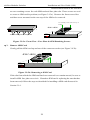
3.1
Locating LE14XXA-Series Switches
The location of a LE14XXA-Series Switch is dependent on the physical layout of the
network. Typically the Switch is placed in a central wiring location where groups of network
devices need to be connected in order to communicate with each other. These Switches are
typically rack mounted in a wiring closet see Section 3.3.2 below), but because they have rubber
feet they can also be installed on a shelf or table top. The compact size of the 8-port LE1401A
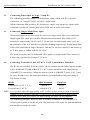
unit allows it to be easily placed in an office or lab area, and it can also be either shelf of wallmounted (see Section 3.3.1 below).
Locate an AC receptacle that is within six feet (2 meters) of the intended LE14XXASeries site. The rugged metal case of the LE14XXA-Series will normally protect it from
accidental damage in a lab or workplace setting. Maintain an open view of the front to visually
monitor the status LEDs. Keep an open area around the unit so that cooling can occur from the
small fan on the left side, while the unit is in operation. See figure below.
Figure 3.1: Location of 8-port LE1401A’s cooling fan exhaust
110-220
VAC
47-63Hz
1.0-0.5A
16
ON
OFF
FAN EXHAUST
Black Box Modular Switches
3.2
Installation and User Guide (8/99)
Connecting Ethernet Media
The Black-Box LE14XXA-Series Fiber Switches are specifically designed to
support all standard Ethernet media types within a single Switch unit. This is
accomplished by using a family of 4-port Modules (4PMs) which can be individually
selected and configured per-port. See Section 2.4 for a description of the 4PMs.
The various media types supported along with the corresponding IEEE 802.3 and
802.3u standards and connector types are as follows:
IEEE Standard
Media Type
Max. Distance
Port Module
Fiber:
100BASE-FX
mm1 Fiber
sgl.m2 Fiber
small form factor mm1 Fiber
10BASE-FL
mm1 Fiber
Copper:
10BASE-T & 100BASE-TX twisted pair
1
3.2.1
2.0km (6,562 ft)
18.0km (95K ft)
2.0km (6,562 ft)
2.0km(6,562 ft)
LE1428C, LE1419C
100m (328 ft)
LE1425C
2
mm = multi-mode
LE1421C
LE1422C, LE1423C
LE1424C
sgl.m = single-mode
Connecting Fiber Optic ST-type, “twist-lock”
The following procedure applies to installations using a 4PM with ST-type fiber
connectors. This procedure applies to ports using a LE1428C or LE1424C.
1. Before connecting the fiber optic cable, remove the protective dust caps from the tips of
the connectors on the 4PM. Save these dust caps for future use.
2. Wipe clean the ends of the dual connectors with a soft cloth or lint-free lens tissue
dampened in alcohol. Make certain the connectors are clean before connecting.
Note:
One strand of the duplex fiber optic cable is coded using color bands at
regular intervals; you must use the color-coded strand on the associated ports at each
end of the fiber optic segment.
3. Connect the Transmit (TX) port (light colored post) on the 4PM to the Receive (RX)
port of the remote device. Begin with the color-coded strand of the cable for this first TX-to
RX connection.
4. Connect the Receive (RX) port (dark colored post on the PM) to the Transmit (TX) port
of the remote device. Use the non-color coded fiber strand for this.
5. The LINK LED on the front of the 4PM will illuminate when a proper connection has
been established at both ends (and when power is ON in the unit). If LINK is not lit after
cable connection, the normal cause is improper cable polarity. Swap the fiber cables at
the 4PM connector to remedy this situation.
17
Black Box Modular Switches
3.2.2
Installation and User Guide (8/99)
Connecting Fiber Optic S C-type, "Snap-In"
The following procedure applies to installations using a 4PM with SC-type fiber
connectors, i.e., using LE1419C, LE1421C single-mode.
When connecting fiber media to SC connectors, simply snap on the two square male
connectors into the SC female jacks of the 4PM until it clicks and secures.
3.2.3
Connecting Single-Mode Fiber Optic
When using single-mode fiber cable, be sure to use single-mode fiber port connectors.
Single-mode fiber cable has a smaller diameter than multi-mode fiber cable (9/125
microns for single-mode, 50/125 or 62.5/125 microns for multi-mode where xx/xx are
the diameters of the core and the core plus the cladding respectively). Single-mode fiber
allows full bandwidth at longer distances, and may be used to connect 10 Mb nodes up
to 10 Km apart, or 18Km with the LE1421C.
The same procedures as for multi-mode fiber applies to single-mode fiber connectors.
Follow the steps listed in Section 3.2.2 above.
3.2.4
Connecting Twisted Pair (RJ-45,CAT3, CAT5, Unshielded or Shielded)
The RJ-45 ports of the LE14XXA-Series can be connected to the following two media
types: 100BASE-TX and 10BASE-T. CAT 5 cables should be used when making
100BASE-TX connections. When the ports are used as 10BASE-T ports, CAT 3 may
be used. In either case, the maximum distance for unshielded twisted pair cabling is
100 meters (328 ft).
Media
Twisted Pair (CAT 3, 4, 5)
Twisted Pair (CAT 5)
IEEE Standard
Connector
10BASE-T
RJ-45
100BASE-TX
RJ-45
NOTE : It is recommended that high quality CAT. 5 cables (which work for both 10 Mb and
100Mb) be used whenever possible in order to provide flexibility in a mixed-speed
network, since dual-speed ports are auto-sensing for either 10 and 100Mb/s.
The following procedure describes how to connect a 10BASE-T or 100BASE-TX
twisted pair segment to the RJ-45 port. The procedure is the same for both unshielded
and shielded twisted pair cables.
18
Black Box Modular Switches
1.
2.
3.
Installation and User Guide (8/99)
Using standard twisted pair media, insert either end of the cable with an RJ-45 plug into
the RJ-45 connector of the port. Note that, even though the connector is shielded, either
unshielded or shielded cables and wiring may be used.
Connect the other end of the cable to the corresponding device
Use the LINK LED to ensure proper connectivity by noting that the LED will be
illuminated when the unit is powered and proper connection is established.
3.3
Table-Top or Shelf Mounting
The LE14XXA-Series Switches can be easily mounted on a table-top or any suitable
horizontal surface, and has four rubber feet to provide stability without scratching finished
surfaces.
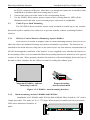
3.3.1
Wall (or Vertical Surface) Mounting, 8-port LE1401A
Each LE1401A Switch is shipped with two metal mounting brackets (and screws) to
allow the unit to be mounted in nearly any desired orientation or position. The brackets are
attached to the metal hub case using one of the metal screws for each bracket, and attached to the
LE1401A through the round hole of the bracket. A user-supplied screw attaches the bracket to
the mounting surface. It is recommended that the mounting brackets be attached to two opposite
corners of the unit. When properly attached, the brackets will extend slightly below the base of
the unit to allow clearance for the rubber feet and for cooling fan exhaust space.
100 Mb/s
Black Box LE1401A
Modular Switch
GARRETT
GARRETT
Proper mounting
bracket attachment
Magnum LE1401A, optional
mounting brackets
Figure 3.1: LE1401A, metal mounting brackets
3.3.2
Rack-mounting, models LE1408A and LE1416A
Installation of a LE1408A and LE1416A Mixed-Media Fiber Switch in a 19” rack is a
simple procedure. The units are 1U (1.75”) high. When properly installed, the front-mounted
LED status indicators should be in
plain
PWR
Black
Magnum
Box
QS5116
LE1416A
Magnum
QS5116
Modular
Fiber Switch
Switch
100/10
1
2
3
4
FDX/HDX
GARRETT
19
LK
ACT
ACT
LK
100/10
ACT
FDX/HDX
100/10
1
2
3
4
FDX/HDX
LK
ACT
1
2
3
4
LK
FDX/HDX
ACT
Black Box Modular Switches
Installation and User Guide (8/99)
view and easy to read. Rack-mount installation requires special rack-mounted brackets and
screws (included with each LE1408A and LE1416A unit). The brackets attach to the front sides
of the Switch, which is then fastened into a standard 19” rack.
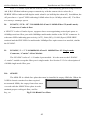
3.4
RJ-45 ports, internal jumper settings for 10/100Mb (auto-negotiation) or for
fixed Half- or Full-Duplex 100Mb, per port
The factory (or default) setting is for auto-negotiation on all RJ-45 ports, which is generally
popular. It works well under most circumstances, but cannot always be
Jumper Settings for Auto-Negotiation, or for 100MB Half or Full Duplex
Jumper
Port
JP2-3,6-7, 10-11
Function
Factory Settings
Pin 2-3,6-7,10-11
Auto-Negotiation
YES
JP1-2, 6-7, 9-10
Pin 1-2, 6-7, 9-10
FDX @100 config
NO
JP1-2, 7-8, 11-12
Pin 1-2, 7-8, 11-12
HDX@100 config
NO
100Mbps Full
Duplex
1
Factory Settings 10/100 Mbps
Auto Negotiation
J1
J1
100 Mb
100Mbps Half
Duplex
J1
100 Mb
100 Mb
10/100 Mb
1 2
AUTO
1 2
Speed
10/100 Mb,
100 Mb
3
1 2
4
3 4
3 4
9 10 11 12
J1
5
1
6
7
8
2
3
4
Jumper Settings for HDX/FDX
and Auto Negotiation
J1
J2
Printed Circuit card
J3
J4
Bottom QPM Retaining
Two(50) Pin
QPM Connectors
(inserts into main board)
TOP
Uplink
LED
Switch
FRONT
Figure 3.4. RJ-45 ports, internal jumper settings. Note: Be certain that the main power is
disconnected before opening the unit or changing any internal jumper settings.
depended upon to work as expected. If auto-negotiation will not function properly in your
setup, internal jumpers allow the speed and mode of the LE14XXA-Series RJ-45 (copper) 4ports to be fixed, even if the attached device may or may not support auto-negotiation. This is
desirable when there are unknown devices presently or potentially connected, which will not
operate correctly with auto-negotiation. Examples include some NICs and most Media
Converters.
20
Black Box Modular Switches
Installation and User Guide (8/99)
Therefore, the default setting of auto-negotiation (copper ports) is generally desirable
because it is widely used and allows for the connection of various devices without reconfiguration. Under certain conditions,(where the connected device is full duplex and does not
support Auto-negotiation; or the connected device does not support Auto-negotiation properly)
no auto-negotiation is better and the internal jumper settings will permit this to be selected on a
per-port basis.
See Section 4.4 for additional information on auto-negotiation functionality.
3.5 Fiber ports, internal jumper settings for 100Mb fixed Half- or Full-Duplex, per port
The factory (or default) setting is for full-duplex on all fiber 100Mbps ports, which is generally
popular. It works well under most circumstances, but cannot always be depended upon to work
as expected. If full-duplex will not function properly in your setup, internal jumpers allow the
speed and mode of the LE14XXA-Series fiber 4-ports to be
Jumper Settings for 100Mbps Fiber Half or Full Duplex
Jumper
Function
Port
Factory Settings
JP1-2, 6-7, 9-10
Pin 1-2, 6-7, 9-10
FDX @100 config
YES
JP1-2, 7-8, 11-12
Pin 1-2, 7-8, 11-12
HDX@100 config
NO
100 Mb
100 Mb
100Mbps Full
Duplex
100Mbps Half
Duplex
1
Factory Settings
J1
J1
100 Mb
100 Mb
1 2 3
Speed
1 2
4
3 4
9 10 11 12
J1
5
1
6 7
8
2
4
3
Jumper Settings for HDX/FDX
J1
J2
J3
Printed Circuit card
Bottom QPM Retaining
Two(50) Pin
QPM Connectors
(inserts into main board)
TOP
1
2
3
4
J4
LED
Figure 3.5. Fiber ports, internal jumper settings. Note: Be certain that the main power is
disconnected before opening the unit or changing any internal jumper settings
21
Black Box Modular Switches
Installation and User Guide (8/99)
fixed, even if the attached device may or may not support full-duplex. This is desirable when
there are unknown devices presently or potentially connected, which will not operate correctly
with full-duplex. Examples include hubs which support only half-duplex by default.
Therefore, the default setting of full-duplex (fiber ports) is generally desirable because
it is widely used and allows for the connection of various devices without reonfiguration(specially along with switches). Under certain conditions,(where the connected
device is half duplex and does not support full-duplex; or the connected device does not support
full-duplex properly) no full-duplex is better and the internal jumper settings will permit this to
be selected on a per-port basis.
3.6
Combo(3+1) ports, internal jumper settings for 10/100 RJ-45 Auto-Negotiation
or 10 or 100Mb or for fixed Half- or Full-Duplex 100Mb, per port
The factory (default) setting is Auto-Negotiation on all RJ-45 ports and full-duplex on
fiber 10 Mbps or 100Mbps ports, which is generally
Jumper Settings for 10/100Mbps RJ-45 Auto-Negotiation,10 or 100Mbps RJ-45 & Fiber Half or Full Duplex
Jumper
Port
Function
JP2 -3, 6-7, 10-11
Pin 2-3, 6-7, 10-11
JP1-2, 6-7, 9-10
Pin 1-2, 6-7, 9-10
Pin 1-2, 7-8, 11-12
JP1-2, 7-8, 11-12
Factory Settings
10/100 Mb
FDX @100 config
YES
10 Mb or 100 Mb
HDX@100 config
NO
10/100 Mbps 10 or100Mbps Full
Duplex
Auto Negotiation
1
Factory Settings
Speed
YES
Auto-Negotiation
J1
10Mb or 100 Mb
10 or100Mbps Half
Duplex
J1
J1
1 2 34
1 2
For RJ-45 &
Fiber port
)
5
1
6 7
8
2
4
3
For RJ-45 &
Fiber port
Jumper Settings for HDX/FDX
J1
J2
Printed Circuit card
J3
J4
Bottom QPM Retaining
Two(50) Pin
QPM Connectors
(inserts into main board)
TOP
1
324
1 2 3 4
3 4
AUTO
9 10 11 12
J1
100 Mb
100 Mb
10/100 Mb
For RJ-45 ports only
LED
Figure 3.6 Combo ports, internal jumper settings. Note: Be certain that the main power is
disconnected before opening the unit or changing any internal jumper settings
popular. Auto-Negotiation on RJ-45 and FDX on fiber port works well under most
circumstances, but cannot always be depended upon to work as expected. If full-duplex will not
function properly in your setup, internal jumpers allow the speed and mode of the LE14XXA-
22
Black Box Modular Switches
Installation and User Guide (8/99)
Series Combo- 4ports to be fixed, even if the attached device may or may not support fullduplex. This is desirable when there are unknown devices presently or potentially connected,
which will not operate correctly with full-duplex. Examples include hubs that support only half
duplex by default.
If auto-negotiation will not function properly in your setup, internal jumpers
allow the speed and mode of the LE14XXA-Series RJ-45 (copper) 4-ports to be fixed, even if
the attached device may or may not support auto-negotiation. This is desirable when there are
unknown devices presently or potentially connected, which will not operate correctly with
auto-negotiation. Examples include some NICs and most Media Converters.
3.7
Fiber 10Mb ports, internal jumper settings for 10Mb fixed Half- or Full-Duplex
at all ports
The factory (default) setting is for half-duplex on all fiber 10Mbps ports,
which is generally popular. HDX works well under most circumstances. If half-duplex on
10Mbps will not function properly in your setup, internal jumpers allow the duplex mode of the
LE14XXA-Series fiber 4- ports to be changed, even if the attached device supports full-duplex.
This is desirable when there are devices connected which will not operate correctly with halfduplex. Examples include Switches that support full-duplex only.
Jumper Settings for 10Mb Fiber Half or Full Duplex
Jumper
Port
OPEN
OPEN
JP3
JP3 JP2-4
Function
Factory Settings
FDX @10Mb config
Pin 2-4
HDX@10Mb config
JP1-3
PIN 1-3
FDX@10Mb config
NO
JFD1 OPEN
OPEN
HDX @10Mb config
YES
JFD1
Speed
10 Mb
10 Mb
NO
YES
10Mb
10Mb
1
JFD1
Factory Settings
1
2
3
4
10Mbps HalfDuplex
JFD1
1
2
3
4
10Mbps Full
Duplex
10Mbps FullDuplex
10Mbps Half Duplex
JF3
JF3
10 Mb
10 Mb
Factory Settings
JF3
JFD1
1
2
3
4
1
4
5
6
7
8
Printed Circuit card
JF3
TOP
Bottom QPM Retaining
Two(50) Pin
JFD1
4PM Connectors
(inserts into main board )
Jumper Settings for HDX/FDX
Jumper Settings for HDX/FDX
LED
23
2
3
Black Box Modular Switches
Installation and User Guide (8/99)
Figure 3.7 10Mbps Fiber ports internal jumper settings.
Note: Be certain that the main power is disconnected before opening the unit or changing any
internal jumper settings
Therefore, the default setting of half-duplex ( fiber ports) is generally desirable because it is
widely used and allows for the connection of various devices without re-configuration.(where the
connected device is half duplex and does not support full-duplex i.e., Hub and media-converters.)
Note: For 10Mbps fiber ports, the user can set the jumpers either at full-duplex or half duplex on
all the four ports. There is no individual port duplex options for 10 Mb port.
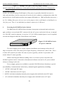
3.8
Powering the LE14XXA-Series Switch
The Black-Box LE14XXA-Series Switches incorporate an internal universal power
supply, and has a recessed male IEC connector for the AC power cord at the left-rear. A manual
power ON-OFF switch is adjacent. A six-foot 115 VAC 60 Hz standard power cord is supplied
with each unit shipped within the United States and Canada.
Figure 3.5: LE14XXA-Series
110-220
VAC
47-63Hz
1.0-0.5A
AC power connector
ON
OFF
The auto-ranging power supply supports installation environments where the AC
voltage is from 90 to 260 volts with a power input frequency of between 47 and 63 Hz. The 8port units will consume just under 20 watts of power typically, and the 16-port units will
consume about 35 watts typically.
When connecting the Ethernet cabling, there is no need to power down the unit.
Individual segments can be connected or disconnected without concern for AC power-related
problems or damage to the unit.
Power supply options are available to suit the LE14XXA-Series Switches to special
high-availability communications and/or heavy industrial-grade applications, including:
*
-48VDC with single DC input,
*
-48VDC with dual-source DC input,
* -48VDC with dual redundant internal power supply units and dual-source DC input,
*
AC with dual redundant internal power supply units and dual-source AC input
24
Black Box Modular Switches
Installation and User Guide (8/99)
See the Appendices of this manual for more details. Use an RFQ for other variations.
25
Black Box Modular Switches
3.9
Installation and User Guide (8/99)
4 Port Module (4PM) Installation
The LE14XXA-Series Modular Switches are normally received from the factory with
all required 4PM modules installed. There may be situations where 4PM cards need to be added
or replaced. In cases where additional 4PM cards are needed, the face plate for an available frontmounted slot must be removed. The following procedure describes this operation.
3.9.1
Preparation for Installing and Removing 4PMs
STOP!!!
Be sure the power cord is unplugged
from the chassis before attempting to remove
and/or replace any 4PM cards.
Failure to do so may result in damage to the unit
and will void the warranty.
Caution- Avoid Static Discharge: The port modules (like most electronic equipment)
are sensitive to static discharge. Use proper ESD measures when handling port
modules.
Step 1.
Make sure the 4PM Card package has all necessary accessories to install it properly.
The 4PM Card package for field installation comes along with a 4PM Card, two 7/16
stand-offs , two #4-40 Pan-Head screws, two #4-40 black color Flat-head screws and
two Headers pin.
Step 2.
Remove Chassis Cover
The LE14XXA-Series chassis are combined with top and bottom part and assembled
together with the help of 20 Philips head screws. There are 7 screws located on front-top of the
unit and three screws each on the left and right edges. Remove these screws. Once these are
removed, the top cover is easily lifted off the chassis base. When the chassis top cover has been
removed, the interior of the unit
20 Phillips Head Screws on Top
is exposed.
Figure 3.9.1a: Removing
Chassis Cover
TopChassis Cover
Power Input
PWR
Magnum QS5116
Fiber Switch
GARRETT
Caution: Be careful not to disturb the power supply.
26
Black Box Modular Switches
Installation and User Guide (8/99)
Looking down into the LE14XXA-Series unit, notice that there are individual 4PM
connector sockets along with two stand-offs for each 4PM card position. There are four 4PM
slots located on the front of the LE1416Amodel, whereas LE1401A and LE1408A has two 4PM
slots in the front. (See Figure 3.9.1b).
AC Power Input
Back of Unit
Power Supply Board
Cooling Fan
Left
Side
Right
Side
with electronic
elements
Media Connector
LED Status Slot
Eight QPM Slots
Front of Unit
Figure 3.9.1b: LE1416A, Top View with Chassis Cover
Step 3.
Remove bottom-front and modules rear top Retaining Screws in any 4PM or
Face Plates
On the bottom-front of the unit, there are two retaining screws for each 4PM card slot
as well as two other retaining screws on the rear top of the module. These four screws are used
to secure a 4PM face plate in position. These screws are also used to secure the individual 4PM
cards, which can be subjected to significant forces from the attached cables. (See Figure 3.9.1c)
Two retaining screws on the rear top of
module
4PM CARDS
MagnumQS5116
J1 J2
Printed Circuit
J4 card
J3
TOP
Fiber Switch
GARRETT
Magnum QS5116
Fiber Switch
1
GARRETT
Two Bottom retaining Screws for each QPM card
Figure 3.9.1c: Front View - 4PM Retaining
Screws hold Face Plates
27
Black Box Modular Switches
3.9.2
Installation and User Guide (8/99)
Installing 4PM Cards in the LE14XXA-Series
Up to four front-mounted 4PM cards may be installed in one LE1416A Fiber Hub
unit. Follow these steps to install a 4PM.
Step 1.
Remove top chassis cover. See procedure in Section 3.9.1 above.
Step 2.
Screw down tightly the two 7/16 stand-offs on the top of pre installed stand-offs from
the factory.
Step 3.
Align the two headers pin on the top of the two sets of socket fixed at the bottom side
of the 4PM module. (Note: After firmly attached the sockets and the header pin, move
the mounted pins slightly tilted towards the front of the chassis.
Step 4.
The figure here illustrates the
Jumper Settings for HDX/FDX
and Auto Negotiation
basic layout of an individual 4PM
J1
J2
Printed Circuit card
card. Each 4PM card fits into the
selected 4PM connector socket
slot. Align the connector pins on
TOP
Uplink
Switch
J3
J4
Two Set of Ten(10) Pin
4PM Connector
(inserts into main board)
LED
FRONT
the bottom of the 4PM card with
the connector socket inside the unit.
Step 5.
Be sure the 4PM front panel is guided into the front slot cut-out first and then
precisely aligned the header pins with the holes in the socket slot mounted on the
board. Slowly and carefully apply enough pressure on both rear corner of 4PM
Module to insert the 4PM card’s pins into position. A click sound will determine the
proper lockup of the two, see Figure 3.9.2b. (If you force the 4PM down when the
pins are not properly aligned with the holes in the header, the pins will become bent
and the 4PM is damaged).
Step 6.
Once inserted, the 4PM card will be secured by the header connector, the front panel
port slot cut-out, and retaining screws. Use #4-40 Pan Head retaining screws to secure
the module rear part and #4-40 Flat Head (Black color) retaining screws for front panel.
NOTE: If a 4PM is difficult to install, try it in another port slot. Some of the port
modules may fit easily in one port slot and be very hard to install in another.
28
Black Box Modular Switches
Installation and User Guide (8/99)
4PM CARDS
Figure 3.9.2a:
J1 J2
J3
Printed Circuit
J4 card
Inserting
TOP
4PM Cards
into a
Magnum QS5116
Fiber Switch
1
GARRETT
LE1416A
NOTE: All 4PM slots need not be filled in order for the LE14XXA-Series unit to be
operational. When leaving 4PM slots empty, always use a face plate ( 4PM-FP) to
cover the slot opening in the front panel. This will maintain proper cooling air flow,
safety, and operation as required by FCC, CE, and other regulations.
Step 7. The figure below shows the top view of 4PM Card after successfully installed the 4PM
cards inside the LE1416A.
AC Power Input
Back of Unit
Power Supply Board
Cooling Fan
Left
Side
Right
Side
with electronic
elements
Media Connector
Four QPM Slots
Front of Unit
Fig. 3.9.2b
Step 8.
Top View : 4PM Module Installed inside a LE1416A
Once all 4PM cards have been installed (including face plates for empty slots), the
chassis cover should be replaced.
3.9.3
Removing 4PM Cards
To properly remove a 4PM card from the Fiber Switch, follow the 3 steps
Step 1.
Remove chassis cover
See procedure in Section 3.9.1 above.
Caution: Be sure the power cord is unplugged.
Step 2.
Remove bottom-front retaining screws for the 4PM and Face Plate
29
below.
Black Box Modular Switches
Installation and User Guide (8/99)
On the bottom-front of the unit there
are two retaining screws for each 4PM card and face plate slot. These screws are used
to secure a 4PM card in position (see Figure 3.9.3a). Remove the front screws first
and then screw mounted on the rear-top of the 4PM to be removed.
Two retaining screws on the rear top of
module
4PM CARDS
MagnumQS5116
Fiber Switch
J1 J2
Printed Circuit
J4 card
J3
GARRETT
TOP
Magnum QS5116
Two Bottom retaining Screws for each QPM card
Fiber Switch
1
GARRETT
Figure 3.9.3a: Front View - Face Plate & 4PM Retaining Screws
Step 3.
Remove 4PM Card
Gently pull the 4PM card up and out of the connector socket (see Figure 3.9.3b).
4PM CARDS
J1
J2
Printed Circuit
J4 card
J3
TOP
Magnum QS5116
Fiber Switch
1
GARRETT
Figure 3.9.3b: Removing a 4PM Card
If the slot from which the 4PM card has been removed is to remain unused, be sure to
install a 4PM face plate cover in it. If another 4PM card is replacing the one that has
been removed, follow the steps as described for installing a 4PM card discussed in
Section 3.9.1.
30
Black Box Modular Switches
4.0
Installation and User Guide (8/99)
OPERATION
This chapter describes the functions and operation of the LE14XXA-Series.
4.1
Switching Functionality
A LE14XXA-Series provides switched connectivity at Ethernet wire-speed among all
of its ports. The LE14XXA-Series supports10/100Mbs for copper media and 10 or 100Mb
separate traffic domain for fiber port to maximize bandwidth utilization and network
performance. All ports can communicate to all other ports in a LE14XXA-Series, but local
traffic on a port will not consume any of the bandwidth on any other port.
LE14XXA-Series units are plug-and-play devices. There is no software configuring to
be done at installation or for maintenance. The only hardware configuration settings are user
options for UP-LINK on RJ-45 4-port. Half / Full duplex mode and 10 or 100Mbps selection for
the switched ports can be done through jumper settings inside the unit. The internal functions of
both are described below.
Filtering and Forwarding
Each time a packet arrives on one of the switched ports, the decision is taken to either
filter or to forward the packet. Packets whose source and destination addresses are on the same
port segment will be filtered, constraining them to one port and relieving the rest of the network
from processing them. A packet whose destination address is on another port segment will be
forwarded to the appropriate port, and will not be sent to the other ports where it is not needed.
Traffic needed for maintaining the operation of the network (such as occasional multi-cast
packets) are forwarded to all ports.
The LE14XXA-Series Switches operate in the store-and-forward switching mode,
which eliminates bad packets and enables peak performance to be achieved when there is heavy
traffic on the network.
Address Learning
All 16-port LE14XXA-Series units have address table capacity of 24K node addresses
(12K for 8-port models), suitable for use in large networks. They are self-learning, so that as
31
Black Box Modular Switches
Installation and User Guide (8/99)
nodes are added or removed or moved from one segment to another, the 4-Port Switch
automatically keeps up with node locations.
An address-aging algorithm causes least-used addresses to fall out in favor of new
frequently-used addresses. To reset the address buffer, cycle power down-and-up.
4.2
Status LEDs
For all LE14XXA-Series models :
PWR
LK
ACT
F/H
100/10
4.3
:
:
:
:
Power LED, ON when AC power is applied to the unit.
Steady ON, Link status for 10 Mbps and 100Mbps operation.
ON with port activity for 10 Mbps and 100Mbps operation.
Full / Half duplex LED, ON when the port is running full duplex, OFF
for half duplex.
: Speed LED, ON when the speed is 100Mbps , OFF when the speed is
10 Mbps
Up-link push-button, for RJ-45 4-port only
LK
1
2
3
4
ACT
button on RJ-45 4-port
x
Figure 4.3 : Up-link push100/10
FDX/HDX
The unit has a manual Up-link
push-button, located on the front panel next to 10/100Mb RJ-45 4-port # 1 which it controls. It
enables the port’s cable to either connect to a user station node (push in) or to be cascaded (push
out) to a 10/100Mb repeater or switching hub in the network. Verify proper Up-link pushbutton position by noting Port 1’s LK (link) LED status, which is illuminated when a proper
link is made.
4.4
Auto-negotiation, for Fast Ethernet copper ports
The LE14XXA-Series Fast Ethernet copper ports can be set for either fixed 100Mb
speed or for 10/100 F/H N-way auto-negotiation per the IEEE802.3u standard. The selection is
made via an internal jumper (see Section 3.4 for jumper-setting instructions). The factory default
setting is for auto-negotiation. At 100Mb-fixed speed, the user may select half- or full-duplex
mode by internal jumpers for each RJ-45 port separately.
32
Black Box Modular Switches
Installation and User Guide (8/99)
One frequently-used application for the 4-Port-Switch copper ports is to connect one
of them using a fiber media converter to another Switch in the network backbone, or to some
other remote 100Mb device. In this case, it is desirable to operate the fiber link at 100Mb speed,
and at either half- or full duplex mode depending on the capabilities of the remote device.
Standard commercially-available Fast Ethernet media converters mostly do not support autonegotiation properly, and require that the switched port to which they are connected be at
100Mb fixed speed. Attachment to 10/100 auto-negotiation ports typically will not work
properly. The 4-Port-Switch’s RJ-45 ports handle this situation by changing the internal jumper
settings. (see Section 3.4)
When 4Port-Switch’s RJ-45 copper ports are set for auto-negotiation and connected to
an another auto-negotiating device, there are 4 different speed and F/H modes selection depending
on what the other device supports. These are: (1) 100Mb full-duplex, (2) 100Mb half-duplex, (3)
10 Mb full-duplex and (4) 10 Mb half-duplex.
The auto-negotiation logic will attempt to operate in descending order and will normally arrive at
the highest order mode that both devices can support at that time. (Since auto-negotiation is
potentially an externally-controlled process, the original “highest order mode” result can change
at any time depending on network changes that may occur). If the device at the other end is not
an auto-negotiating device, the 4Port-Switch’s RJ-45 ports will try to detect its idle signal to
determine 10 or 100 speed, and will default to half-duplex at that speed per the IEEE standard.
General information Auto-negotiation per-port for 802.3u-compliant switches occurs when:
the devices at both ends of the cable are capable of operation at either 10 Mb or
100Mb speed and/or in full- or half-duplex mode, and can send/receive autonegotiation pulses, and . . .
-- when the second of the two connected devices is powered up*, i.e., when
LINK is established for a port, or
-- when LINK is re-established on a port after being lost temporarily.
33
Black Box Modular Switches
•
Installation and User Guide (8/99)
NOTE – some NIC cards only auto-negotiate when the computer system that they
are in is powered up. These are exceptions to the “negotiate at LINK – enabled” rule
above, but may be occasionally encountered.
When operating in 100Mb half-duplex mode, cable distances and hop-counts may be
limited within that collision domain. The Path Delay Value (PDV) bit-times must account for all
devices and cable lengths within that domain. For Black Box LE14XXA-Series Fast Ethernet
switched ports operating at 100Mb half-duplex, the bit time delay is 50BT.
4.5
Auto-negotiation for 10 Mb ports, half- or full-duplex mode
Full-duplex Ethernet provides separate Transmit and Receive data paths, enabling
simultaneous bi-directional collision-free data movements on a port. The network topology must
be a “star” type, not a “bus” type. With full-duplex mode, the cable distance is only limited by
the physical layer line driver and cable attenuation. There are no collision-domain restrictions or
limitations.
The LE14XXA-Series Switches perform half- or full-duplex mode auto-negotiation
independently on all switched ports. If the device or node on the other end of a port’s attached
cable supports F/H mode auto-negotiation or is set to operate as full-duplex, the 4-Port Switch
will negotiate to run full-duplex. If the attached device or node doesn’t support F/H mode autonegotiation (for example, if it is a 10 Mb repeater or a standard 10 Mb hub), the 4-Port-Switch’s
RJ-45 ports will default to operate at half-duplex.
4.6
Flow-control, IEEE 802.3x standard
Black-Box LE14XXA- Series Switches incorporate a flow-control mechanism for Full-
Duplex mode. The purpose of flow-control is to reduce the risk of data loss if a long burst of
activity causes the switch to save frames until its buffer memory is full. This is most likely to
occur when data is moving from a 100Mb port to a 10 Mb port, and the speed difference makes
the 10Mb port unable to keep up. It can also occur when multiple 100Mb ports are attempting
to transmit to one 100Mb port, and in other protracted heavy traffic situations.
LE14XXA-Series Fiber Switches implement the 802.3x flow control (non-blocking) on
Full-Duplex ports, which provides for a “PAUSE” packet to be transmitted to the sender when
the packet buffer is nearly filled and there is danger of lost packets. The transmitting device is
commanded to stop transmitting into the 4-switch port for sufficient time to let the Switch
34
Black Box Modular Switches
Installation and User Guide (8/99)
reduce the buffer space used. When the available free-buffer queue increases, the Switch will send
a “RESUME" packet to indicate the transmitter to start sending the packets. Of course, the
transmitting device must also support the 802.3x flow control standard in order to communicate
properly during normal operation.
Note: When in Half-Duplex mode, the Modular-switch implements a backpressure algorithm on 10/100 Mb ports for flow control. That is, the switch prevents
frames from entering the device by forcing a collision indication on the half-duplex
ports that are receiving. This temporary “collision” delay allows the available buffer
space to improve, as the switch catches up with the traffic flow.
4.7
Power Budget Calculations for LE14XXA-Series 4PM’s with Fiber Media
Receiver Sensitivity and Transmitter Power are the parameters necessary to compute
the power budget. To calculate the power budget of different fiber media installations using
LE14XXA models, the following equations should be used:
OPB (Optical Power Budget) = PT(min) - PR(min)
where PT = Transmitter Output Power, and PR = Receiver Sensitivity
Worst case OPB = OPB - 1dB(for LED aging) - 1dB(for insertion loss)
Worst case distance = {Worst case OPB, in dB} / [Cable Loss, in dB/Km]
where the “Cable Loss” for 62.5/125 and 50/125µm (M.m) is 2.8 dB/km,
and the “Cable Loss” for 100/140 (Multi-mode) is 3.3 dB/km,
and the “Cable Loss” for 9/125 (Single-mode) is 0.5 dB/km
The following data has been collected from component manufacturer’s (HP’s and Siemens’) web
sites and catalogs to provide guidance to network designers and installers.
Fiber Speed,
Port
Mode
Module Std.
Std. Wave Cable X’mitr R’cvr Wors Worst* typica typical*
km
Size Outpu Sens. t distanc
l
distanc
fdx lengt µm
t
PR OPB, e Km, OPB,
e
(hdx) h
PT , dB ,dB dB
fdx
dB Km, fdx
nm
62.5/12 -15.0 -31
14
5
17
6
LE1424C 10 Mb Multi2
850
5
-9.5 -31 19.5 5.9
23.5
7
(2)
FL mode
100/14 -19.5 -31 9.5
3.4
13.5
4.8
0
50/125
LE1428C 100Mb Multi2
1300 62.5/12 -20
FX mode (0.4)
5
-23.5
50/125
100Mb Single- 18+
LE1421C FX
1300 9/125 -15
mode (0.4)
-31
9.0
2.5
14
5
-31
5.5
2.0
12
4
-31
14
28
17.5
35
2
LE1422C 100Mb Multi1300 62.5/12 -20
FX mode (0.4)
5
-23.5
50/125
-31
9.0
3.0
15.8
5.5
-31
5.5
2.0
12.2
4.0
35
Black Box Modular Switches
Installation and User Guide (8/99)
2
LE1422C 100Mb Multi1300 62.5/12
FX mode (0.4)
5
-14
-31
15
5
16
5.7
* Note: The use of either multi-mode or single-mode fiber to operate at 100Mbps speed over
long distances (i.e., in excess of approx. 400 meters) can be achieved only if the
following factors are both applied:
•
The 100Mb fiber segment must operate in full-duplex (FDX) mode, i.e. the full-duplex
(factory default) setting for 100Mbps fiber ports must be used, and
•
The worst-case OPB of the fiber link must be greater than the fiber cable’s passive
Attenuation.
(Attenuation = Cable loss + LED aging loss + Insertion loss + safety factor)
5.0
Introduction - LE14XXA-Series 4-Port Modules(4PM)
This chapter describes each 4-Port Module (4PM), including appearance,
functionality, and status displays.
5.1
Inspecting the Package and Product
This section applies only to 4PMs shipped as separate items, i.e., 4PMs not factory
installed in a LE14XXA-Series 4PM slot.
Examine the shipping container for obvious damage prior to installing a 4PM; notify
the carrier of any damage which you believe occurred during shipment or delivery.
Inspect the contents of this package for any signs of damage and ensure that the items
listed below are included.
This package should contain:
One or more 4PMs.
Installation instructions, with illustrations
Remove the 4PM(s) from the shipping container. Be sure to keep the shipping container
should you need to ship any of the 4PMs separately at a later date.
In the event there are items missing or damaged contact your supplier. If you need to
return the unit, use the original shipping container if possible. Refer to Chapter 5 for
specific return procedures.
5.2
Product Description
36
Black Box Modular Switches
Installation and User Guide (8/99)
An important feature of the LE14XXA-Series is the use of 4-Port Modules (4PMs)
and for flexible mixed-media connectivity to RJ-45 and fiber media use of Combo 4port module. Since the LE14XXA-Series have dual-speed capability for copper-port,
the front port slots are designed to support all standard Ethernet media types at 10 or
100Mps speed. Each 4PM provides one port for connecting one Ethernet segment
with its individual connector type and media.
For a list and brief illustration of 4-Port Module types, refer to Section 2.4
Each 4PM is individually described in the following sections.
5.2.1
LE1428C, 100Mb multi-mode FX-ST-4-port Module, “twist lock” connector
The LE1428C is a multi-mode 100Mbps fiber optic 4-port
module equipped with a dual ST-type
100BASE-FX, and 10BASE-FL
ST Connectors
connector. It functions as a fiber optics
transceiver to support 100BASE-FX
FDX/HDX 1
LK
1
2
3
4
network segments. When installed in a
LE14XXA-Series Fiber Switches, it
1
2
3
2
3
4
ACT
supports fiber optic cable distances up the
1
IEEE-specified 100Mbps shared-collision-
ACTIVITY 2
domain distance limits, i.e., typically 2km at
3
full-duplex and 412m at half-duplex.
LINK
FULL/HALF
DUPLEX MODE
The module is equipped with an Activity (ACT) LED, a Link (LK) LED which
indicates proper connectivity with the remote device when lit, and the FDX/HDX LED indicates
the full or half-duplex mode. Lettering on the front of the module identifies it as “100 FX” to
avoid confusion with other similar-looking 10 Mb fiber 4PMs.
5.2.1a
LE1424C, 10 Mbps multi-mode FL-ST-4-port type, “twist-lock” connector
The LE1424C is a multi-mode 10 Mbps fiber optic module equipped with a dual ST-
type connector. It looks similar to the 100Mb LE1428C, but has the lettering “10 Mb” on the
front to distinguish it. It supports fiber optic cable distances up the IEEE -standard 10 Mb
distance limits , i.e., typically 2km at full-duplex and at half-duplex.
Each port has an Activity (ACT) LED indicating packets being received, a
Link (LK) LED that indicates proper connectivity with the remote device when lit, and a
FDX/HDX LED to indicate full-duplex mode when lit (or half-duplex when off). Lettering on the
37
Black Box Modular Switches
Installation and User Guide (8/99)
front of the module identifies it as “10 FL” to avoid confusion with other similar-looking 100Mb
fiber QPMs.
5.2.2
LE1419C 100Mbps multi-mode FX-S C-4-port type, “snap-in” connector
100BASE-FX Multi-Mode
SC Connectors
The LE1419C is also a multi-mode 100Mbps
fiber optic transceiver module, similar to the LE1428C.
1
2
3
It has the same LEDs indicating port activity (ACT),
1
FDX/HDX
LK
1
2 ACT
3
4
Link (LK), and FDX.HDX operational, and the same
face-plate lettering.
2
3
4
ACT
4
1
While the functionality of the these two
ACTIVITY 2
FULL/HALF
DUPLEX MODE
3
modules is the same, the LE1419C is equipped with an
LINK
SC-type "snap -in" connector instead of an ST-type.
2.3
LE1421C 100Mbps single-mode FX-S C-type, “snap-in” connector
The LE1421C is a single-mode 100Mbps fiber optic module equipped with a dual SC-
type connector. It functions as a full fiber optic transceiver to the Modular-Switches, supporting
four single-mode fiber network segments.
100BASE-FX Single-Mode
SC Connectors
TheLE1421C, when installed in a
LE14XXA-Series Modular Switch operating at
3
100Mbps full-duplex, supports single-mode fiber
cable lengths of as much as 25+ Km (see Power
1
2
FDX/HDX 1
LK
1
2 ACT
3
4
2
3
4
ACT
Budget, Section 4.5)
Each port is equipped with an Activity
(ACT) LED, LINK(LK) LED, (10/100) Speed and
(HDX/FDX) Half or full Duplex mode identical to
1
ACTIVITY
3
2 LINK
FULL/HALF
DUPLEX MODE
those of the LE1419C. To distinguish the singlemode LE1421C from the multi-mode LE1419C, the label “Sgl. M.” is at the top of the faceplate
of the LE1421C.
38
Black Box Modular Switches
5.2.4
Installation and User Guide (8/99)
LE1422C, 100Mb multi-mode FX 4-Port, MTRJ small-form-factor connector
LE1422C is a multi-mode fiber optic 4-port module equipped with a small-form-factor
MTRJ-type connector. It looks almost like
an RJ-45 port, but it is black in color. The
100BASE-FX MTRJ
Connectors
M T-RJ’s small size and ease of connection
1
2
3
FDX/HDX
1
LK
1
2
3
4
ACT
2
make it a good choice for 100Mbps “fiber-
3
4
to-the-desktop” Ethernet connectivity.
When installed in a LE14XXA-Series full-
ACTIVITY 2
1
duplex Switch, it supports fiber optic cable
3
distances up the IEE-standard 100Mbps
shared-collision-domain distance limits, i.e.,
LINK
FULL/HALF
DUPLEX MODE
“small-form-factor”
typically 2 km at full-duplex and 412m at
half-duplex.
The functionality of this 100BASE-FX multi-mode 4PM is same as the ST and SCtypes, and it is equipped with the same ACTIVITY (ACT), LINK (LK) LEDs to indicate
proper connectivity with the remote device and (FDX/HDX) indicate the FULL OR HALF
DUPLEX MODE at the port. It has the same “100Mb FX” lettering on the faceplate. Note that
the other end of the fiber cable may have a different connector, not necessarily an M T-RJ type.
5.2.5
LE1423C, 100Mbps multi-mode FX 4-Port, VF-45 small-form-factor connector
39
Black Box Modular Switches
Installation and User Guide (8/99)
LE1423C is a 4-port multi-mode fiber FX “small-form-factor” VF-45 connector used
primarily in 100Mbps fiber-to-the-desktop links. Its size is similar to the MT-RJ port, but the
VF-45 shell is slightly larger. When not in use, its appearance is distinctive because it has a tiny
hinged door over the port hole to act as a dust cover.
100BASE-FX MV45
Connectors
When installed in a LE14XXA-Series
Modular Switches at full-duplex, it supports fiber
optic cable distances up the IEEE-standard 100Mbps
3
1
2
FDX/HDX
1 LK
distance limits, i.e., typically 2 km at full-duplex and
ACT
2
3
4
412m on half-duplex.
The small size, about the same as an RJ-45,
2
ACTIVITY
1
reduces the size of wiring panels in wiring closets
LINK
3 FULL/HALF
while providing the advantage of “future-proof” fiber
DUPLEX MODE
optic technology.
“small-form-factor”
The cable port is a “plug-in” connector, with
both fiber strands terminated in one housing that cannot be improperly inserted. The module is
equipped with a LINK (LK) LED to indicate proper connectivity with the remote device, an
ACTIVITY (ACT) LED that flashes to show when Fast Ethernet packets are being received and
a (FDX/HDX) LED indicate the full-duplex mode when lit (or half-duplex when off).
5.2.6
LE1425C (Twisted Pair), 10/100Mb TP 4-Port
The LE1425C module supports Ethernet twisted pair segments of any standard length.
It is equipped with 4-port RJ-45 connector with 10/100 and auto-negotiating capability on each
port. The RJ-45 connector is shielded to minimize emissions and will allow both unshielded
twisted pair (UTP) and shielded twisted pair (STP) cable connections.
The LE1425C 4-port module is equipped with a Media Dependent InterfaceCrossover (MDI-X) push-button to allow for one cascaded connections. This feature eliminates
the need for a special twisted pair crossover
10/100BASE-T,4Port
RJ-45 Connectors
cable when connecting to a hub or another
switch.
1
2
x
With the push-button in the IN (X)
LK
1
2
3
4
ACT
position, the PM-TP port is used for
Cross-Over
Push Switch
cascaded and up-link connections (i.e.: a
100/10
1
40
FDX/HDX
4
ACTIVITY
2
3 FULL/HALF
3
LINK
4
SPEED
Black Box Modular Switches
Installation and User Guide (8/99)
connection to another hub or switch typically.) When used for segments going to workstations
and other user node device connections, the MDI-X push-button should be in the OUT (=)
position.
The LE1425C will support 10BASE-T unshielded twisted pair wiring (UTP)
environments with maximum segment distances up to 100m (325 ft.), or shielded twisted pair
wiring (STP) of 150m (500 ft.). Each port has an Activity (ACT) LED indicating packets being
received, a Link (LK) LED that indicates proper connectivity with the remote device when lit, a
FDX/HDX LED to indicate full-duplex mode when lit (or half-duplex when off), and a “speed”
LED indicating 100Mb when lit (or 10 Mbps when off).
Important Note: For the LE1425C Crossover Push-button OUT for workstations and user connections.
IN for Up-Link connections to other hubs, etc.
The RJ-45 pins normally (TP crossover push-button DOWN) are per the standard for
hubs-to-users twisted pair wiring: 1 = receive+, 2 = receive-, 3 = transmit+, 6 = transmit-,
other pins not used. When the TP crossover push-button is UP, the pins of the RJ-45 port
are per the standard for up-links using twisted pair wiring, i.e., the transmit and the receive
pairs are exchanged: 1 = transmit+, 2 = transmit-, 3 = receive+, 6 = receive-, other pins not
used.
5.2.7 LE1426C, “3TP + 1F” 3 10/100Mb RJ-45 and 1 100Mb Fiber SC (multi-mode)
Connector Combo 4-Port
10/100BASE-T and 100BASE-FX Combo
Quad-Port Connectors
The LE1426C Combo 4-port
2
supports three auto-negotiating twisted pair
1
LK
5
2
3
4
ACT
ports at 10/100Mbps FDX/HDX, and one
100/10
FDX/HDX
4
fiber port with 100Mbps multi-mode FX SC
1
connector. The three RJ-45 ports on the right
ACTIVITY
2
3
LINK
3 FULL/HALF
DUPLEX (RJ-45)
operate the same as those in the same place
1
HDX/FDX
5
4
SPEED
FULL/HALF DUPLEX(FIBER)
on the QPM-RJ45 module.
The fiber SC connector functions as a fiber optics transceiver to support 100BASEFX network segments. When installed in a LE14XXA-Series Fiber Switches, it supports fiber
optic cable distances up the IEEE-standard 100Mbps distance limits, i.e., typically 2km at fullduplex and 412m at half-duplex. The factory default setting is for full-duplex operation, and a
jumper on the module must be moved to select half-duplex. (See Section 3.4).
41
Black Box Modular Switches
Installation and User Guide (8/99)
Each 3+1 combo 4-port has an Activity (ACT) LED indicating packets being received,
a Link (LK) LED that indicates proper connectivity with the remote device when lit, a
FDX/HDX LED to indicate full-duplex mode when lit (or half-duplex when off). In addition, the
RJ-45 ports have a “speed” LED indicating 100Mb when lit (or 10 Mbps when off). The fiber
port is always 100Mbps speed.
5.2.8
LE1427C, “3TP + 1F” 3 10/100Mb RJ-45 and 1 100Mb Fiber ST (multi-mode)
Connector Combo 4-Port
The LE1427C is also a Combo 4-port, supports three auto-negotiating twisted pair ports at
10/100Mbps and one fiber port with 100Mbps multi-mode similar to the FX SC connector. It
has the same LEDs indicating port activity (ACT), Link (LK), (10/100) Speed, FDX/HDX
operational and the FDX LED for multi-mode 100Mbps fiber optic transceiver module, similar
to the LE1426C.
5.2.9
LE1429C, “3 + 1” 3 10/100Mb RJ-45 and 1 100Mb Fiber SC Single-mode
Connector, “Combo” 4-Port Module
The LE1428C is also a 3+1 Combo 4-port module. It is the same as the LE1426C
“3+1 combo” module except the fiber port is single-mode. See Section 5.2.3 for a description of
the 100Mb single-mode fiber port.
5.2.10
4PM-FP
The 4PM-FP is a blank face plate that must be installed in empty 4PM slot. When the
LE14XXA chassis contains less than required
front mounted 4PMs, the empty front slots must
be covered with the 4PM-FP face plate in order
to maintain proper cooling air flow, and for
safety, etc.
Fig.5.2.10 Blank Face Plate
42
Black Box Modular Switches
6.0
Installation and User Guide (8/99)
TROUBLESHOOTING
If problems should develop during installation or operation, follow the suggestions
below prior to calling Technical Support for help. If you are unsure of any procedure
described in this chapter, or if the LE14XXA is not operating as expected, do not
attempt to repair or alter the unit. Contact Black Box for assistance.
6.1
Before Calling for Assistance
1.
If you have difficulty installing or operating the LE14XXA Modular Switches, refer to
Chapters 3 and 4. Make sure that the various other components of the network are
working.
2.
Check the cables and connectors to make sure that they have been properly connected
and the cables/wires have not been crimped or in some way impaired during installation.
3.
Check that the AC power cord is plugged into a functioning electrical outlet. Make sure
that the AC power cord is properly plugged into the Modular Switches. Use the PWR
LED to verify that the unit is receiving proper power.
43
Black Box Modular Switches
4.
Installation and User Guide (8/99)
If the problem is isolated to a network device other than the LE14XXA -Series Modular
Switch, replace the problem device with a known good device. Verify whether or not
the problem is corrected. If it is not, go to step 5. If the problem is corrected, the
Modular Switches and its associated cables will function properly.
5.
6.2
If the problem still exists, contact Black Box.
When Calling for Assistance
If you determine that your LE14XXA-Series Modular Switch is malfunctioning, do
not attempt to alter or repair the unit. It contains no user-serviceable parts. Contact Black
Box at (724) 746-5500.
Before you do, make a record of the history of the problem. Black Box will be able
to provide more efficient and accurate assistance if you have a complete description,
including:
•
•
•
•
6.3
the nature and duration of the problem.
when the problem occurs.
the components involved in the problem.
any particular application that, when used, appears to create the problem or
make it worse.
Shipping and Packaging Information
If you need to transport or ship your LE14XXA -Series Modular Switch:
•
Package it carefully. We recommend that you use the original container.
•
If you are shipping the LE14XXA -Series Modular Switch for repair, make sure you
include everything that was in the original package. Before you ship, contact Black
Box to get a Return Materials Authorization (RMA) number.
Ship the package to:
Black Box Corporation
1000 Park Drive
Lawrence, PA 15055
Phone: (724) 746-5500
Fax:
(724) 746-0746
44
Black Box Modular Switches
Installation and User Guide (8/99)
Black Box Corporation
The World’s Source for Connectivity
Copyright 1999. Black Box Corporation. All rights reserved.
1000 Park Drive · Lawrence, PA 15055
·
(724) 746-5500
45
· Fax (724) 746-0746