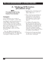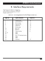
1
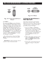
SEPTEMBER 1993
AC400A
AC401A
Real Color 16 LCD Projection Panel
Monochrome 16 LCD Projection Panel
CUSTOMER
SUPPORT
INFORMATION
Order toll-free in the U.S. 24 hours, 7 A.M. Monday to midnight Friday: 877-877-BBOX
FREE technical support, 24 hours a day, 7 days a week: Call 724-746-5500 or fax 724-746-0746
Mail order: Black Box Corporation, 1000 Park Drive, Lawrence, PA 15055-1018
Web site: www.blackbox.com • E-mail: [email protected]
REAL COLOR AND MONOCHROME 16 LCD PROJECTION PANELS
FEDERAL COMMUNICATIONS COMMISSION
RADIO FREQUENCY INTERFERENCE STATEMENT
This equipment generates, uses, and can radiate radio frequency energy
and if not installed and used properly, that is, in strict accordance with the
manufacturer’s instructions, may cause interference to radio communication.
It has been tested and found to comply with the limits for a Class A
computing device in accordance with the specifications in Subpart J of
Part 15 of FCC rules, which are designed to provide reasonable protection
against such interference when the equipment is operated in a commercial
environment. Operation of this equipment in a residential area is likely to
cause interference, in which case the user at his own expense will be required
to take whatever measures may be necessary to correct the interference.
Changes or modifications not expressly approved by the party responsible
for compliance could void the user’s authority to operate the equipment.
This digital apparatus does not exceed the Class A limits for Radio noise emission from
digital apparatus set out in the Radio Interference Regulation of Industry Canada.
Le présent appareil numérique n’émet pas de bruits radioélectriques dépassant les limites
applicables aux appareils numériques de la classe A/ prescrites dans le Règlement sur le
brouillage radioélectrique édicté par Industrie Canada.
1
REAL COLOR AND MONOCHROME 16 LCD PROJECTION PANELS
TRADEMARKS
UL® is a registered trademark of Underwriters Laboratories Incorporated.
Macintosh® and Apple® are registered trademarks of Apple Computer, Inc.
IBM® and PS/2® are registered trademarks of IBM Corporation.
MS-DOS® is a registered trademark of Microsoft Corporation.
Compaq® is a registered trademark of Compaq Computer Corporation.
Dell® is a registered trademark of Dell Corporation.
Epson® is a registered trademark of Seiko Epson C orporation.
Sharp® is a registered trademark of Sharp Corporation.
Toshiba® is a registered trademark of Toshiba Corporation.
Zenith® is a registered trademark of Zenith Electronics Corporation.
Any other trademarks mentioned in this manual are acknowledged to be the property
of the trademark owners.
2
REAL COLOR AND MONOCHROME 16 LCD PROJECTION PANELS
Contents
Chapter
Page
1. Specifications.................................................................................................. 4
2. Introduction ...................................................................................................
2.1 Description ............................................................................................
2.2 Shipping Container Contents ..............................................................
2.3 General Guidelines ...............................................................................
5
5
6
7
3. Installation...................................................................................................... 8
3.1 Setup Instructions ................................................................................. 8
3.2 Connecting the Projection Panel to a Desktop Computer ................12
3.3 Connecting the Projection Panel to an IBM PC
Compatible Laptop Computer ............................................................13
3.4 Connecting the Projection Panel to a Macintosh
Series Computer ...................................................................................14
4. Operation .......................................................................................................15
4.1 Adjusting the Projection Panel ............................................................15
4.2 Non-Shift Control Button Functions ...................................................17
4.3 Shift-Activated Control Button Functions ...........................................19
4.4 Using the Control Buttons to Make Adjustments...............................22
4.5 User Menu.............................................................................................23
4.6 Moving Through the User Menu.........................................................24
4.7 Adjusting a Menu Option ....................................................................24
5. Maintenance and Troubleshooting ..............................................................28
5.1 Cleaning the Display Surface ...............................................................28
5.2 Cleaning the Projection Panel Filter ...................................................28
5.3 Troubleshooting Guide ........................................................................29
Appendix A: Working With Colors (AC400A only).........................................32
Appendix B: Interface Requirements ...............................................................33
B.1 Power Connector Polarity ....................................................................34
B.2 Screen Area...........................................................................................34
Appendix C: Special Guidelines for IBM and Compatibles ............................36
C.1 IBM Computers with Two Display Cards ............................................36
C.2 Instructions for Activating Portables and Laptops .............................37
3
REAL COLOR AND MONOCHROME 16 LCD PROJECTION PANELS
1. Specifications
Resolution — 640 x 480
Power — UL® approved 12 VDC,
1.5A power supply
Size — 15.3"H x 13.1"W x 2.6"D
(38.9 x 33.3 x 6.6 cm)
Weight — 5.9 lb. (2.7 kg)
4
CHAPTER 2: Introduction
2. Introduction
2.1 Description
For remarkably impressive
presentations, use the Real Color
or Monochrome 16 LCD Projection
Panel. The Panel, which projects
16 real colors or 16 shades of grey,
delivers the computer compatibility
and ease of use you never thought
possible in an LCD projection panel.
Fig. 2-1 illustrates the Panel coupled
with an overhead projector.
Fig. 2-1. The Projection Panel on an Overhead Projector.
5
REAL COLOR AND MONOCHROME 16 LCD PROJECTION PANELS
The Projection Panel is easy to
use. Simply connect the Panel to a
computer graphics card and place
the unit onto an ordinary overhead
projector. The data and graphics
normally displayed on the computer
monitor will be projected in images
that you can easily see in typical
room lighting. The Projection Panel
has a temperature-regulating fan,
which works with the heat-producing
overhead projector, to hold the
liquid crystal display (LCD) to the
optimum temperature. You can use
the Projection Panel on a wide range
of overhead projectors rated up to
650 watts.
The Projection Panel, with a
640x480 pixel display, is compatible
with the Macintosh® series and
Macintosh II series; with Apple® IIGS
RGB; with IBM® PC and compatibles
in CGA, EGA, and VGA modes, and
with the IBM PS/2® with VGA or CGA.
2.2 Shipping Container Contents
The components shown in Fig. 2-2
are included with the Projection
Panel.
1. Projection Panel
2. This User Manual
3. 12-volt power supply
4, 6. 15-pin Mac II, LC, Apple IIgs
5. 15-pin VGA
If any pieces are missing when
you first open the box, contact Black
Box immediately.
1
4
5
6
2
3
Fig. 2-2. The Projection Panel and Included Components.
6
CHAPTER 2: Introduction
2.3 General Guidelines
Follow these guidelines when you
use the Projection Panel.
• Be sure the Projection Panel
is on whenever the overhead
projector is turned on.
CAUTION
If the Projection Panel is not
on when it is on top of an
operating overhead projector, the Panel could
sustain damage.
• Do not use the Projection Panel
for extended periods of time on
an overhead projector known for
discoloring or melting standard
transparencies.
• When you use the Panel with a
high-wattage projector or if you
notice extreme discoloration of
the Panel, periodically remove
the Panel from the overhead
projector to allow it to cool.
• Handle the Projection Panel as
you would anything made of
glass. Be especially careful not
to drop it.
• You can easily clean the
Projection Panel with standard
non-abrasive glass cleaner. Apply
the cleaner to the cleaning cloth
and then wipe the glass surface
lightly. Do not use excessive
amounts of liquid or pressure on
the top or bottom optical panels.
• Avoid scratching the Projection
Panel surface with sharp metal
objects. The top surface is made
of glass or a scratch-resistant
hardened polymer. If you need
to clean the surface, use normal
glass-cleaner solution. Do not
use abrasive cleaners, solvents,
or other harsh chemicals.
• Avoid leaving the Projection
Panel in direct sunlight or
extreme cold for extended
periods of time.
• The bottom of the Panel can
become very hot to the touch
after use. Be careful to let the
Panel cool before lifting it.
• Do not block the Projection
Panel fan or free air movement
under and around the Panel.
Air flows from back to front.
• Turn the overhead projector off
and unplug the Projection Panel
when not in use.
7
REAL COLOR AND MONOCHROME 16 LCD PROJECTION PANEL
3. Installation
3.1 Setup Instructions
This chapter explains the
connections you must make between
the three pieces of equipment you
will be using—the Projection Panel,
your computer, and monitor. Be
sure to follow the instructions for
your type of computer.
Fig. 3-1. Projection Panel and Overhead Projector,
Showing Cable Connections.
8
CHAPTER 3: Installation
3.1.1 CABLES
Three cables are supplied with the
Projection Panel:
1. A Macintosh II/Macintosh
LC/Apple IIGS loop-through
cable
2. A VGA/MCGA loop-through
cable
3. A loop-through cable for EGA,
CGA, or Macintosh video
15-pin MacII
The cables that come with your
Projection Panel are used to connect
the computer’s video port to the
Projection Panel and the monitor.
Each of the three cables has a 26-pin
connector for the Projection Panel,
a connector matching the video card
and a connector for the monitor.
The Projection Panel receives the
computer’s signals, amplifies the
signals, and sends them out to the
monitor.
15-pin VGA
9-pin VGA
Fig. 3-2. Cables.
9
REAL COLOR AND MONOCHROME 16 LCD PROJECTION PANEL
3.1.2 CONNECTING THE PROJECTION
PANEL TO YOUR COMPUTER
You are going to make eithertwo or
three connections. You will connect
the computer’s graphics card to the
Projection Panel, the Projection
Panel to the wall outlet with the
power supply, and, optionally, the
Projection Panel to the computer’s
monitor.
The steps you need to follow are
given in Section 3.1.3. Illustrations
on the pages following the steps
show the cable connections for
your configuration.
3.1.3 SETTING UP THE PROJECTION
PANEL FOR PROJECTION
To set up the Projection Panel for
projection, follow these steps:
1. Set up your overhead projector
and plug it into the wall outlet.
Turn it on to be sure it is
working properly and position
it so it projects onto the screen.
2. Place the Projection Panel on
the overhead projector so the
connectors and controls are on
the right side of the projector
as you face the front of the
projector.
3. Connect power to the Projection
Panel, but do not connect a
video signal yet. This will bring
up a test pattern.
Move the Projection Panel on
the projector until the lines
are solid rather than rainbows.
Adjust the tint for the best color
saturation or the contrast for the
best greyscale.
10
10
CHAPTER 3: Installation
Computer
Cable
IBM or compatible
with VGA Graphics Card
or IBM PS/2 with built-in
VGA or MCGA Graphics
15-pin
IBM or Compatible
with EGA or CGA
Graphics Card or
Classic Style Macintosh
9-pin
Macintosh II Series or
Macintsoh LC, Apple IIGS
15-pin
Looks like
Fig. 3-3. Selecting the Proper “Y” Cable for Your Computer.
Refer to Appendix A for additional
important information on how to
properly place a Projection Panel
on an overhead projector.
4. Follow the instructions in this
table to select the proper “Y”
cable for your computer:5.
Connect the 26-pin end (marked
LCD) of the “Y” cable to the
Projection Panel.
NOTE
Skip step 6 if you are
connecting to a classic-style
Macintosh.
11
6. Unplug the computer monitor
cable from the graphics card.
Plug the monitor to the short
end (marked Monitor) of the
Projection Panel cable to the
computer monitor.
7. Plug the long end of the
Projection Panel cable (marked
for the appropriate computer)
to the computer’s video port.
8. Tighten the thumb screws on
the cable connectors to ensure
proper grounding.
11
REAL COLOR AND MONOCHROME 16 LCD PROJECTION PANEL
3.2 Connecting the Projection Panel
to a Desktop Computer
Figure 3-4 shows how to connect the
Projection Panel to typical desktop
computers, which include CGA,
EGA, VGA, Macintosh II, and
Macintosh LC setups.
All cables are labeled (for
example, LCD, Monitor, VGA, etc.)
to indicate where they connect.
Fig. 3-4. Desktop Computer with a Y-Cable.
12
CHAPTER 3: Installation
3.3 Connecting the Projection Panel
to an IBM PC Compatible Laptop
Computer
Figure 3-5 shows a typical laptop
installation.
Fig. 3-5. Typical Laptop Installation.
When the external port is
activated, many laptop computers
automatically turn off their internal
display. For more information, see
Appendix C or your computer
manual for typical laptop commands.
The short end of the loop-through
cable is not connected in this
installation.
CAUTION
The Projection Panel is not
compatible
with
the
Macintosh laptop. Do not
attempt to connect the
Projection Panel to a
Macintosh laptop. Serious
damage to the computer or
Projection Panel could
result.
13
REAL COLOR AND MONOCHROME 16 LCD PROJECTION PANEL
3.4 Connecting the Projection Panel
to a Macintosh Series Computer
Figure 3-6 shows how to connect the
Projection Panel to a Macintosh
series computer.
Fig. 3-6. Macintosh Series Computer.
Because classic-style Macintosh
computers do not have a video
connector, you must install an
internal adapter. The Macintosh
128, 512, and Plus require an A10
adapter. The SE and SE/30 require
an A20. The Macintosh Classic
requires an A21. Call your dealer for
more information. Note that the
short end of the loop-through cable
is not connected in this installation.
14
NOTE
Because the SE and Plus
models of the Macintosh
computer only display in
monochrome at a resolution
of 512x342 pixels, a Real
Color 16 LCD Projection
Panel connected to one of
these models will only
project monochrome and will
not fill the entire Projection
Panel screen.
CHAPTER 4: Operation
4. Operation
4.1 Adjusting the Projection Panel
At this point, bring up the software
you want to project. You should be
projecting an image on the screen.
This section will show you how to
adjust the Projection Panel to get
clear, crisp images. You can adjust
the Projection Panel using the
10-function keypad.
Some of the buttons are autorepeat buttons; that is, pressing and
holding these buttons causes them
to constantly send instructions.
Other buttons toggle through a
fixed number of settings and require
you to press the button each time to
trigger the next setting.
4.1.1 CONTROL BUTTON FUNCTIONS
There are ten operating control
buttons on the Projection Panel. A
SHIFT button, located in the lower
left corner, allows several of these
buttons to have a dual function
(non-shift functions are printed
in gray, shift functions are in blue).
Six of the buttons are combined
as dual-action switches.
15
REAL COLOR AND MONOCHROME 16 LCD PROJECTION PANELS
level
tint
position
reset
clear
palette
reverse
shift
menu
position
syncsync+
Fig. 4-1. Projection Panel Keypad.
Table 4-1. Non-Shift and Shift Keys.
16
NON-SHIFT
KEYS
SHIFT
KEYS
Tint (up/down)
Contrast (up/down)
Sync+
Position (up/down)
Position (left/right)
Clear
Reverse
Level (up/down)
SyncMenu (toggle)
Reset
Palette
CHAPTER 4: Operation
4.2 Non-Shift Control Buttons
To activate one of the non-shift
buttons (printed in grey) on the
operating control panel, just press
the button.
level
contrast
4.2.1 TINT (TRUE COLOR)
Press the Tint key to adjust the color.
The Tint Up key adds red and green
to the image. Blue levels are
affected by a mix of red and green.
Fig. 4-3. Contrast (Monochrome).
level
tint
Fig. 4-2. Tint (True Color).
4.2. CONTRAST (MONOICHROME)
The Contrast key allows the user
to adjust the brightness of the
displayed image for optimum
viewing. Contrast Up increases the
perceived brightness of all shades
equally, while Contrast Down
decreases the brightness of all
shades equally. There are 64
contrast levels available.
4.2.3 SYNC+
The Projection Panel has been
calibrated to automatically match
signals sent by specific computer
systems (CGA, EGA, VGA, PS/2, and
Macintosh series). However, each
individual video card varies slightly
from others.
syncsync+
Fig. 4-4. Sync+.
17
REAL COLOR AND MONOCHROME 16 LCD PROJECTION PANELS
Projected characters or graphics
may appear to shimmer because of
differences in signal outputs of some
computers. Press the Sync+ button
until projected characters “lock” into
position and shimmering is
eliminated.
4.2.5 POSITION, LEFT OR RIGHT
Press the up or down position
button to center the image
horizontally on the screen. This
button auto-repeats.
Each time Sync+ is pushed, it finetunes the Projection Panel to match
signals from the graphics system.
Sync+ continuously cycles forward
through all 16 positions (press syncto cycle back to a good sync
position).
menu
position
4.2.4 POSITION, UP OR DOWN
Press the up or down position
button to center the image vertically
on the screen. This button autorepeats.
Fig. 4-6. Position, Left or Right.
position
Fig. 4-5. Position, Up or Down.
18
4.2.6 CLEAR
Pressing the Clear button cleans any
unwanted random patterns that may
have appeared on the screen outside
the image area. In some cases,
positioning the image will leave a
trail of data. Use the Clear button
to remove this unwanted data.
You may also use this control to
blank the screen by clearing the test
pattern to all black or all yellow.
Disconnect the video signal to bring
up the test pattern and press Clear.
Background color depends on the
state of Reverse. Pressing Clear
again will restore the screen.
CHAPTER 4: Operation
reset
clear
Fig. 4-7. Clear.
4.2. REVERSE
If you wish to reverse the way you see
an image, light letters on a dark
background or dark letters on a light
background, press the Reverse
button. Pressing it again causes the
display to return to the original
image. All colors will be switched
with their complements.
See Appendix A for more information on working with colors.
palette
reverse
Fig. 4-8. Reverse.
4.3 Shift-Activated Control Button
Functions
The functions shown on the
operating control panel in blue
letters are activated when the Shift
button is held down while a
command button is pushed.
19
REAL COLOR AND MONOCHROME 16 LCD PROJECTION PANELS
Fig. 4-9. Holding Down Shift and Pushing a Command Button.
4.3.1 SYNCEach time Sync- is pushed, it fine
tunes the Projection Panel to match
signals from the graphics system.
Sync- continuously cycles backward
through all 16 positions.
syncshift sync+
Fig. 4-10. Sync-.
20
4.3.2 RESET
The master reset function, holding
down the Shift button and pressing
Reset, returns the display settings
(Position, Sync, Palette, Reverse, and
Level) for the video mode being
displayed to factory defaults.
The Reset function does not affect
Tracking, Text Mode, Text Slice,
Tint, Contrast, or EGA mode unless
the menu is showing on the screen.
If the menu is displayed, all display
settings and menu items, including
the color bars, are reset to factorydefault values.
CHAPTER 4: Operation
shift
reset
clear
Fig. 4-11. Reset.
4.3.3 PALETTE
Pressing the Palette button selects
the displayed color palette size. This
button allows you to switch between
8-color and 16-color displays on the
Real Color Panel and select one of
seven, color-to-greyshade mappings
on the Monochrome panel.
palette
shift reverse
Fig. 4-12. Palette.
4.3.4 LEVEL UP AND LEVEL DOWN
The Level button adjusts the color
mapping to compensate for
computer-to-computer differences.
Just as colors look different on
different monitors, there will always
be some color differences between
the monitor and the Projection
Panel. If the color match between
the monitor and the Projection
Panel is not satisfactory, the level can
be adjusted to change the mapping.
It is important, however, to ensure
that the Tint or Contrast is set
correctly prior to adjusting the level.
Level Up or Level Down increases
your flexibility by allowing you to
choose which tones of
color/greyscale will be projected.
Pressing Level Up increases the
limits of the range of tone which will
be depicted by that color. Pressing
Level Down will cause a smaller
band of tone to be depicted as a
given color. There are 64 steps. The
level controls operate only on analog
video signals such as those from
VGA, MCGA, or Macintosh II display
systems.
21
REAL COLOR AND MONOCHROME 16 LCD PROJECTION PANELS
level
tint
shift
shift
menu
position
Fig. 4-14. Menu.
Fig. 4-13. Level Up and Level
Down.
4.3.5 MENU
Pressing the Menu control displays
the User Menu, which allows you to
adjust the initial color balance and
tracking, change the text mode and
language, and flip the projection
image. The User Menu also provides
information about the video input.
After you display the User Menu, use
the Position (< >) control buttons
to move within and between menu
options, and the Position ( ^ or v )
to change an option.
For information about the User
Menu, see the section later in this
chapter.
Shift-Menu (either button) moves
you in or out of menu mode.
22
4.4 Using the Control Buttons to
Make Adjustments
Now that you have reviewed the
functions of each of the control
buttons, here is the order in which
you use them to achieve the best
possible projected image.
1. Press the Tint or Contrast
buttons up or down to change
the color of your image or text
for the best viewing. Tint or
contrast is easiest to adjust with
an image that contains large
areas of different color or
greyscale.
2. Move the image on the screen
with the Position Up, Down,
Left, and Right buttons until
it is centered.
3. Focus the overhead projector
until the image is crisp and
clear.
CHAPTER 4: Operation
NOTE
The Projection Panel must
be placed correctly on the
overhead projector. Incorrect
placement may cause the
Projection Panel to project
blurry or mis-converged
images. For more information, see Appendix A.
4. Press Sync until the image is
locked in as a solid image with
no shimmer or movement. This
button toggles through the
present settings to the specific
computer graphics type. Press
Sync until you achieve the best
image.
5. For VGA, MCGA, and Macintosh
II, you may need to hold down
Shift and press Level Up or
Level Down to choose the best
color matching. For best results
when adjusting the level, display
an image that has a wide range
of colors.
For VGA text display, you may
need to adjust the Text Mode if
the text characters are jagged or
shimmering.
6. If your computer is one of the
standard supported systems,
your image should be fully
adjusted at this point. However,
if your computer is any other
type, you may see evenly spaced
fuzzy vertical lines, or text may
appear to be too wide or too
narrow for the screen. To
correct this problem, go to the
User Menu (press the Menu
control button) and adjust the
tracking.
7. You may want to press Reverse
to select either light characters
on a dark background or dark
characters on a light
background. Use the setting
which best suits your graphics or
text.
8. To restore factory-set default
values, hold down Shift and
press Reset while the menu is
being displayed.
4.5 User Menu
Pressing the Menu control button
displays the User Menu on your
computer’s monitor. The User
Menu allows you to change the color
balance, adjust the tracking, and
control how information is
displayed.
23
REAL COLOR AND MONOCHROME 16 LCD PROJECTION PANELS
NO VIDEO
RED GRN
TRACK Level
TRACK 800
LANGUAGE
HORZ
15.3
REAR PROJECT OFF
VERT
+60
TEXT SLICE
1
MODE
15
TEXT MODE
ON
EGA 64
OFF
ENGLISH
Fig. 4-15. Projection Panel Menu.
4.6 Moving Through the User Menu
After you display the User Menu, use
the Position control buttons (left
and right) to move within and
between option columns.
These keys are auto-repeat
buttons; that is, pressing and
holding these buttons causes them
to constantly send instructions.
Tint/.Contrast and Level buttons
are still active when in Menu Mode.
4.7 Adjusting a Menu Option
Use the Position Up and Down
control buttons to adjust menu
options. These keys auto-repeat.
Pressing Shift RESET when the
menu is showing resets all menu
items, including the color
adjustments, to factory-default
values.
24
4.7.1 COLOR BALANCE (TRUE COLOR
ONLY)
Adjust the Tint control to get the
best colors. Black and white will
always have a reddish tint. If the
colors still need adjustment, display
the menu by pressing Shift-Menu. If
you press Shift-Reset when the menu
is displayed, the color balance will be
reset to its factory default values.
Resetting to default and slightly
adjusting the Tint control may be
enough to improve the colors.
CHAPTER 4: Operation
If the colors still need adjustment,
follow these steps and use the red
and green adjustments to fine-tune
the panel:
1. Move the green bar down until
you have a rich red and a solid
black.
2. Move the red bar down until you
have a rich, true green. If cyan
turns green, the green bar turns
brown, and the white turns
magenta, you have moved the
bar too far down.
3. If your white is magenta-tinted,
drop the red bar down a few
steps until it is white, but not so
far that the black turns red.
White and black, however, are
always going to be slightly
reddish.
4.7.2 EGA 64
For the True Color Panel, EGA 64
may affect the color brown on some
EGA systems and some VGA systems
when in EGA mode. If your brown is
displaying as light red, turn on the
EGA 64 setting.
4.7.3 TRACKING
The Tracking adjustment bar allows
you to match the Projection Panel’s
internal clock to the different
computer graphics signals. Using
tracking allows the Projection Panel
to project crisp images from a range
of computer graphics systems. There
are 64 tracking levels.
You need to adjust the tracking
if the display shows evenly spaced,
fuzzy vertical lines, or if the
projected image is too wide or too
narrow for the screen.
Move the tracking bar down (lower
numbers) to make the image look
narrower. Move the tracking bar up
(higher numbers) to make the
image look wider. The default Track
value is shown with the Video
Information. As you move the
Tracking adjustment bar up or
down, the Track value changes.
Move the Tracking adjustment bar
up or down until the fuzzy lines
move apart on the screen or
disappear, or the text fits the screen.
The ideal is to have no bars visible
and all the projected text or graphics
on the screen.
For the Monochrome Panel, EGA
64 may allow you to get all 16 shades
of grey instead of 15 shades.
Default value is OFF.
25
REAL COLOR AND MONOCHROME 16 LCD PROJECTION PANELS
Fig. 4-16. Tracking.
4.7.4 VIDEO/NO VIDEO
The Video column provides
information about the current video
input. If video is not present, the
User Menu displays “No Video,” with
no Horizontal or Mode information
and the test pattern or blank screen
visible in the image area.
The Video information column
shows the tracking setting (described
previously), the horizontal sync
frequency and polarity (HORZ), the
vertical sync frequency and polarity
(VERT), and the video mode
number (MODE).
These values (except for Track)
are for informational purposes and
cannot be adjusted. If you are
experiencing problems, be sure to
write down these values before
calling Technical Support.
26
4.7.5 LANGUAGE
Menus can be displayed in either
English, French, German, Italian, or
Spanish. The User Menu allows you
to choose the language. The default
is English.
4.7.6 REAR PROJECTION
Select ON to flip the image from left
to right for rear projection screens.
The default is OFF. Rear projection
allows you to use a standard
overhead projector without complex
mirror setups for rear projection.
CHAPTER 4: Operation
Fig. 4-17. Rear Projection.
4.7.7 TEXT SLICE
Text Slice allows you to adjust VGA
text characters to look their best.
The Projection Panel discards one
of seven pixels to adjust characters.
Text Slice allows you to choose
which of the seven pixels you want
the Projection Panel to discard. Text
Slice is ON for only 720 text mode
(VGA text). Text Slice has no effect
on characters when Text Mode is
OFF. Adjust the Text Slice until your
characters are solid and fully
formed.
4.7.8 TEXT MODE
The Projection Panel screen area is
640 pixels wide. Text that extends
beyond 640 pixels may be either
compressed or truncated. When text
(or graphics) is compressed, it is
tightly spaced to fit the display
screen. Truncated text (or graphics)
is not respaced to fit the display;
rather, anything beyond the right
edge of the screen display is not
shown.
Selecting ON for the Text Mode
locks VGA text to solid pixels (no
shimmering). CGA graphics,
however, may be compressed. Unless
you regularly project CGA graphics
with the Projection Panel, text mode
should be set to ON.
Text Mode works only when text
is present. For example, this mode
works in VGA text but not in VGA
graphics.
You are now ready to begin a
presentation.
Now that the Projection Panel is
properly connected and you have
adjusted the image on the screen,
you are ready to begin projecting
your computer data and graphics.
The projected images will be live
from your computer and change as
you change the computer data.
27
REAL COLOR AND MONOCHROME 16 LCD PROJECTION PANELS
5. Maintenance and Troubleshooting
The information in this chapter
is a guide to the cleaning and
maintenance of your Projection
Panel, as well as to locating and
solving possible problems.
5.1 Cleaning the Display Surface
1. Handle the Projection Panel
as you would anything made of
glass. Be especially careful not
to drop it.
The hardened polymer surface
of the Real Color 16 LCD
Projection Panel (AC400A) is
designed to be scratch and dent
resistant. However, you should
avoid scratching it with sharp
metal objects. The Monochrome
16 LCD Projection Panel
(AC401A) surface is made of
glass, and you should follow the
instructions in step 2.
28
2. If the surface needs cleaning,
you can use any normal nonabrasive glass cleaner on it.
Apply the cleaner to a cleaning
cloth and then wipe the surface
lightly. Do not use excessive
amounts of liquid. Do not use
abrasive cleaners, solvents, or
other harsh chemicals.
5.2 Cleaning the Projection Panel
Filter
The filter, which is located at the
front of the Projection Panel,
catches dust particles before they
get into the Projection Panel. You
need to routinely clean the filter. To
clean the filter, follow these steps:
1. Unsnap the fan cover.
CHAPTER 5: Maintenance and Troubleshooting
Filter
Fig. 5-1. The Projection Panel Filter.
2. Gently remove the filter and
clean it by washing it in gentle
soap. Be sure to let the filter dry
completely before re-inserting it
in the Projection Panel.
The frequency with which you
will need to clean the filter
depends on how often you
use the Panel. Typically, you
will need to clean the filter
approximately once every
three to six months or when
the Projection Panel overheats
from a clogged filter.
5.3 Troubleshooting Guide
Before calling Technical Support
for assistance, attempt to solve the
problem by checking this
troubleshooting guide.
Problem: Nothing on screen.
Possible Causes and Solutions:
• You may not have any power
or you may be using the wrong
power supply. Check to see that
the proper Projection Panel
power supply is being used
with the Projection Panel.
29
REAL COLOR AND MONOCHROME 16 LCD PROJECTION PANELS
• The power supply may not be
plugged into a live AC outlet.
Check to ensure that the power
supply is connected to the
Projection Panel and to a live
AC wall outlet.
• Your power supply may be
plugged into a power strip
that is not turned on.
• Your overhead projector may not
be set up correctly. Check to
see that the projector is on and
plugged in properly. Also check
the bulb, and make sure the
overhead deflector is correctly
positioned.
• You Projection Panel may not be
adjusted properly. Also, check
and adjust the contrast and level
control settings.
Problem: Color or VGA text not
being projected.
Possible Causes and Solutions:
• Your level control may need
to be adjusted. Adjust the
Projection Panel level control up
or down until the text is visible.
• Your software may be displaying
colors that are too similar. Set
your software to increase the
difference between displayed
colors.
Problem: Image not centered on
the screen.
Possible Causes and Solutions:
• Adjust position to center image
on screen.
Problem: Only the test pattern is
being displayed.
Possible Causes and Solutions:
• Your Projection Panel video
cables may not be connected
correctly. Check to see that the
cable is connected to the video
port on the computer’s graphics
card.
• Your computer graphics system
may not be set up correctly.
Check the following: your
computer’s color graphics card
is turned on; your computer has
a compatible graphics card; and
the computer’s external video
card has been turned on.
Problem: Image is too wide or
narrow for screen.
Possible Causes and Solutions:
• You may need to adjust the
tracking to reduce or enlarge
the projected image.
• Check to see that your computer
is using a compatible graphics
card.
• You may be using a highresolution display card.
Make sure your computer is
compatible. Change the
resolution if you can.
30
CHAPTER 5: Maintenance and Troubleshooting
Problem: Image is out of focus.
Problem: The projected colors do
not match the monitor.
Possible Causes and Solutions:
Possible Causes and Solutions:
• Overhead is not adjusted
correctly. Adjust overhead until
image is in focus.
• The surface of the Projection
Panel or overhead projector may
need cleaning.
Problem: Vertical lines or bleeding.
• Adjust the level and/or tint
controls. However, just as there
are differences in the displays
of different monitors, there will
always be some differences
between the computer screen
and the projected image.
Possible Causes and Solutions:
• Adjust tint to minimize vertical
lines or bleeding from around
projected boxes or borders.
31
REAL COLOR AND MONOCHROME 16 LCD PROJECTION PANELS
A. Working With Colors
(AC400A only)
NOTE
This appendix applies only
to the Real Color 16 LCD
Projection Panel (AC400A).
Convergence
Color alignment on a screen is
known as convergence. Colors that
are aligned correctly, pixel by pixel,
will produce sharp lines on the
screen. If the colors do not align
correctly, objects on the screen will
seem to have multi-colored shadows.
Poor color convergence or
misconvergence, then, creates
blurred images, which can cause
eye strain.
You can adjust convergence by
positioning the Projection Panel on
an overhead projector. To adjust the
convergence, follow these steps:
32
1. Apply power to the Projection
Panel, but do not connect a
video cable to it.
2. Place the Projection Panel on
your projector and turn the
projector on. A test pattern
consisting of a series of color
bars and a line grid should
appear.
3. Looking at the projection
screen, move the Projection
Panel around on the projector
until all lines, both horizontal
and vertical, are solid. (As you
move the Projection Panel
around, you will see the lines
split apart from single dark lines
to rainbow-colored lines).
4. Position the Projection Panel
on the spot at which the lines
are the most converged.
APPENDIX B: Interface Requirements
B. Interface Requirements
The Projection Panel is equipped
with a 26-pin connector. Table B-1
shows the pin assignments for the
26-pin connector.
Table B-1. Pin Assignments for the 26-pin connector.
Input Pin
Signal Description
Output Pin
1
2
8
6
7
9
16
17
18
20, 21
22
23
24
25
26
Vertical sync
Horizontal sync
Blue analog
Intensity TTL
Green TTL
Red analog
Blue TTL
Red TTL
Green analog
GND
GND
Key (TTL/analog sensor)
GND
GND
Hercules
10
11
14
12
13
15
3
4
5
19
33
REAL COLOR AND MONOCHROME 16 LCD PROJECTION PANELS
B.1 Power Connector Polarity
The power connector on your
Projection Panel uses the polarity
shown in Fig. B-1.
Fig. B-1. Power Connector Polarity.
The Projection Panel is shipped with
a 12-Volt, 1.5-Amp power supply
designed to work specifically with
the Projection Panel. Many portable
computers and peripherals use
similar-looking power supplies.
CAUTION
Do not substitute other
power supplies. You could
damage the Projection Panel.
To double check, look for the
label on the Projection Panel power
supply.
34
B.2 Screen Area
The Projection Panel’s screen is
640 by 480 pixels. (Pixels are tiny
rectangular dots that are turned on
and off by the computer to create
images.) Various computer monitors
have different pixel dimensions.
Depending on the computer’s
resolution, the images may not fill
the entire screen.Fig. B-2 represents
the Macintosh display. Table B-2 lists
several common computer monitors
and their screen areas.
APPENDIX B: Interface Requirements
640 pixels
512 pixels
480 pixels
342 pixels
Fig. B-2. Macintosh Display.
Table B-2. Common Computer Monitors and Their Screen Areas.
Computer Monitor
Projection Panel Screen Area
AT&T, CGA
EGA
Macintosh
Macintosh II, VGA
Macintosh LC
640 x 400 pixels
640 x 350 pixels
512 x 342 pixels
640 x 480 pixels
512 x 384 pixels
35
REAL COLOR AND MONOCHROME 16 LCD PROJECTION PANELS
C. Special Guidelines for IBM
and Compatibles
C.1 IBM Computers with Two Display
Cards
If your computer has both a color
and monochrome display, you may
need to turn on the color card.
Because your computer will only
display on one monitor at a time,
you need to ensure that the color
display is on when using the
Projection Panel.
You can do this in a variety of ways.
Some computers require special
commands other than
MS-DOS® commands. The best
reference for finding these
commands is your computer
manual.
See Section C.2 for instructions
on how to setup a color or
monochrome display.
36
For most IBM and IBM
compatibles:
1. Follow the instructions for
setting up the Projection Panel.
2. Insert your MS-DOS disk in drive
A. (Skip this step if you have a
hard drive.)
3. When the DOS prompt appears,
type MODE CO80
(CO for color, the number 80
for 80 columns).
4. The color card should be
activated.
If you have a monochrome
monitor and want to switch back,
at the DOS prompt, type:
MODE MONO
The Projection Panel will go off
and your monochrome monitor
will come on.
APPENDIX C: Special Guidelines for IBM and Compatibles
C.2 Instructions for Activating
Portables and Laptops
Refer to Table C-1 for commands to
activate or de-activate the Projection
Panel.
Table C-1. Portable and Laptop Activation Chart.
Computer
Model
Activate Port
Command
De-activate
Command
Video
Standard
Compaq® portable II
Compaq portable III
Compaq SLT
Compaq LTE/286
Dell® 316LT
Epson® LT
Ctrl Alt <
Ctrl Alt <
Ctrl Alt <
Ctrl Alt <
Ctrl Alt F11
Switch for CRT
On
Switch for CRT
On
Active port
Ctrl Alt Tab
Ctrl Alt Tab
Ctrl Alt Tab
Ctrl Alt Tab
Active Port
Sw2 on off off off
Fn F10
Switch for CRT
On
Fn End
Ctrl Alt End
Fn End
Ctrl Alt End
Ctrl Alt >
Ctrl Alt >
Ctrl Alt >
Ctrl Alt >
Ctrl Alt F10
Switch for LCD
On
Switch for LCD
On
N/A
Ctrl Alt Tab
Ctrl Alt Tab
Ctrl Alt Tab
Ctrl Alt Tab
N/A
Sw2 off on on on
Fn F10
Switch for LCD
On
Fn Home
Ctrl Alt Home
Fn Home
Ctrl Alt Home
CGA
CGA
VGA
CGA
VGA
CGA
Epson 286e
Gridcase 1200 series
Gridcase 1400 series
Gridcase 1520
Gridcase 1530
Gridcase 1535 EXP
IBM P70 386
Mitsubishi
Packard Bell PB286LT
Sharp® PC-5541
Toshiba® 1000
Toshiba 1100
Toshiba 1200, 1600
Toshiba 3100
EGA
CGA
VGA
CGA
CGA
CGA
VGA
EGA
EGA
VGA
CGA
CGA
CGA
CGA
00
37
REAL COLOR AND MONCHROME 16 LCD PROJECTION PANELS
Table C-1 (continued). Portable and Laptop Activation Chart.
Computer
Model
Activate Port
Command
De-activate
Command
Video
Standard
Toshiba 3100-e
Toshiba 3100sx
Toshiba 3200sx
Toshiba 3200
Toshiba 5100
Toshiba 5100/100
Toshiba 5200
Toshiba 5100/100
Zenith 128, 170, 180,
183, 184, Supersport
Zenith Supersport 286e
Supersport sx
Supersport
Ctrl Alt End
Active Port
Active Port
Fn End
Ctrl Alt End
Active Port
Active Port
Active Port
Fn F10
Ctrl Alt Home
N/A
N/A
Fn Home
Ctrl Alt Home
N/A
N/A
N/A
Fn F10
EGA
VGA
VGA
EGA
EGA
EGA
VGA
VGA
CGA
Fn F10
Fn F10
VGA
00
38
Index
Numbers
512x342 pixels, 15
640 by 480 pixels, 36
640x480 pixel display, 7
C
CGA, 7, 10,, 18, 28
E
EGA, 7, 10,, 18, 21, 26
M
MCGA, 10, 24
MS DOS, 38
R
RGB, 7
V
VGA, 7, 10, 13, 18, 22, 24, 26, 28
39
© Copyright 1993. Black Box Corporation. All rights reserved.
1000 Park Drive • Lawrence, PA 15055-1018 • 724-746-5500 • Fax 724-746-0746