1
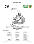
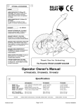
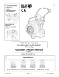
Thank
You
for
Selecting
The Powerful QL Series Truck Loader Vacuum
Operator Owner's Manual
QL2300KOEU
Specifications
Optional Accessories
QL2300KOEU
ENGINE HP(kW)
ENG. WEIGHT
ENG. TYPE
MODEL NO.
FUEL CAPACITY
OIL CAPACITY
UNIT (w/ hose boom ) WEIGHT
ELBOW WEIGHT
HOSE (w/ nozzle) WEIGHT
TOTAL WEIGHT
SHIPPING WT.
BATTERY NOT INCLUDED:
REQUIRES 12 V BATTERY, 40 AH, 240 CCA MIN.
U1 SERIES GROUP BATTERRY FOR PROPER FIT
UNIT SIZE (ASSEMBLED W/EXHAUST, NO HOSE):
OVERALL WIDTH: 32" (0.81m)
Part No. 790321
INTAKE
23 HP (17.14kW) TWIN OHV VANGUARD
90# (40.8 kg)
TWIN OHV KOHLER ELECTRIC START
PA-76559
8 qt (7.57L) Remote Tank, Oil Pump
2.0 qt. (1.9L)
313# (142.0 kg)
40# (18.1 kg)
39# (17.7 kg)
392 lb (177.8 kg)
476 lb (215.9 kg)
OVERALL LENGTH: 58"(1.47m)
OVERALL HEIGHT: 74" (1.82m)
Page 1 of 12
HOSE REPLACEMENT KIT
P/N 810776
Standard on QL2300KOEU units. [10"(254mm)]
diameter.
EXHAUST
EXHAUST HOSE KIT
P/N 790114
[8"(203mm) x 5' (1.5m)] Quick release coupler and
flexible steel hose increases exhaust distance.
TRAILER
TRAILER QL
P/N 790112
Heavy duty spring axle trailer designed for towing your QL.
Allows unit to be mounted for pickup from rear and both sides.
Form No. F050304B
IN THE INTEREST OF SAFETY
BEFORE STARTING ENGINE, READ AND UNDERSTAND THE “ENTIRE OPERATOR'S MANUAL & ENGINE MANUAL.”
THIS SYMBOL MEANS WARNING OR CAUTION. DEATH, PERSONAL INJURY AND/OR PROPERTY
DAMAGE MAY OCCUR UNLESS INSTRUCTIONS ARE FOLLOWED CAREFULLY.
WARNING!
The engine exhaust from this product contains chemicals known to the
State of California to cause cancer, birth defects or other reproductive
harm.
21. DO NOT touch hot muffler, cylinder, or
WARNING: DO NOT
13. DO NOT tamper with governor springs,
governor links or other parts which may
change the governed engine speed.
1. DO NOT run engine in an enclosed area.
Exhaust gases contain carbon monoxide, an
odorless and deadly poison.
14. DO NOT tamper with the engine speed
selected by the engine manufacturer.
2. DO NOT place hands or feet near moving
or rotating parts.
15. DO NOT check for spark with spark plug
or spark plug wire removed. Use an
approved tester.
3. DO NOT store, spill or use gasoline near
an open flame, or devices such as a stove,
furnace, or water heater which use a pilot
light or devices which can create a spark.
16. DO NOT crank engine with spark plug
removed. If engine is flooded, place throttle
in “FAST” position and crank until engine
starts.
4. DO NOT refuel indoors where area is not
well ventilated. Outdoor refueling is
recommended.
17. DO NOT strike flywheel with a hard
object or metal tool as this may cause
flywheel to shatter in operation. Use proper
tools to service engine.
5. DO NOT fill fuel tank while engine is
running. Allow engine to cool for 2 minutes
before refueling. Store fuel in approved
safety containers.
6. DO NOT remove fuel tank cap while
engine is running.
18. DO NOT operate engine without a
muffler. Inspect periodically and replace, if
necessary. If engine is equipped with
muffler deflector, inspect periodically and
replace, if necessary, with correct deflector.
7. DO NOT operate engine when smell of
gasoline is present or other explosive
conditions exist.
19. DO NOT operate engine with an
accumulation of grass, leaves, dirt or other
combustible material in the muffler area.
8. DO NOT operate engine if gasoline is
spilled. Move machine away from the spill
and avoid creating any ignition until the
gasoline has evaporated.
20. DO NOT use this engine on any forest
covered, brush covered, or grass covered
unimproved land unless a spark arrester is
installed on the muffler. The arrester must
be maintained in effective working order by
the operator. In the State of California the
above is required by law (Section 4442 of
the California Public Resources Code).
Other states may have similar laws.
Federal laws apply on federal lands.
9. DO NOT transport unit with fuel in tank.
10. DO NOT smoke when filling fuel tank.
11. DO NOT choke carburetor to stop
engine. Whenever possible, gradually
reduce engine speed before stopping.
fins because contact may cause burns.
22. DO NOT run engine without air cleaner
or air cleaner cover.
23. DO NOT operate during excessive
vibration!
24. DO NOT leave machine unattended
while in operation.
25. DO NOT park machine on a steep grade
or slope.
WARNING: DO
1. ALWAYS DO remove the wire from the
spark plug when servicing the engine or
equipment TO PREVENT ACCIDENTAL
STARTING.
2. DO keep cylinder fins and governor
parts free of grass and other debris
which can affect engine speed.
3. DO pull starter cord slowly until resistance is felt. Then pull cord rapidly to avoid
kickback and prevent hand or arm injury.
4. DO examine muffler periodically to be
sure it is functioning effectively. A worn or
leaking muffler should be repaired or
replaced as necessary.
5. DO use fresh gasoline. Stale fuel can
gum carburetor and cause leakage.
6. DO check fuel lines and fittings frequently
for cracks or leaks. Replace if necessary
7. Follow engine manufacturer operating
and maintenance instructions.
8. Inspect machine and work area before
starting unit.
12. DO NOT run engine at excessive
SOUND
speeds. This may result in injury & /or
Sound tests conducted were in accordance with 2000/14/EEC
damage to unit.
and were performed on 4/13/2004 under the conditions listed:
TABLE OF CONTENTS
NOTE: Sound power level listed is the highest value for any model in this manual. Please
refer to serial plate on the unit for the sound power level for your model.
2
SAFETY INSTRUCTIONS
3
GENERAL SAFETY
ASSEMBLY
3
4
PARTS BAG & CONTROLS
4
LABELS
5-7
OPERATION
8-9
MAINTENANCE
PARTS DRAWING & LIST 10 - 11
12
TROUBLESHOOTING
12
WARRANTY
○
○
○
○
○
○
○
○
○
○
○
○
○
○
○
○
○
TEMPERATURE:
50.5° F (10.3° C)
WIND SPEED:
0.5 MPH (0.8 kmh)
○
○
○
○
○
○
○
○
○
○
○
Part No. 790321
Sunny
GENERAL CONDITION:
Vibration levels at the operators handles were
measured in the vertical, lateral, and longitudinal
directions using calibrated vibration test equipment.
Tests were performed on 05/07/98 under the
conditions listed:
GENERAL CONDITION:
Partly Cloudy
○
○
○
Sound level of 89 dBA at operator position
○
○
○
○
○
○
○
○
○
○
○
○
○
○
○
○
○
○
○
○
VIBRATION
VIBRATION LEVEL 0.02g
110 dB
North West
WIND DIRECTION:
39 %
HUMIDITY:
BAROMETRIC PRESSURE:
30.18" Hg (767mm Hg)
Page 2 of 12
TEMPERATURE:
WIND SPEED:
WIND DIRECTION:
HUMIDITY:
BAROMETRIC PRESSURE:
69° F (20.6° C)
8 MPH (12.8 kmh)
N
76 %
29.71" Hg (755mm Hg)
Form No. F050304B
GENERAL SAFETY
For your safety and the safety of others, these directions should be followed:
Do not operate this machine without first reading
·DO NOT operate during excessive vibration.
owner's manual and engine manufacturer's manual.
·DO NOT remove hose until engine has been turned off and has
Use of Ear Protection is recommended while
come to a complete stop.
operating this machine.
·DO NOT operate machine with hose or exhaust elbow removed.
Use of Eye and Breathing protection is recom·DO NOT use this machine for vacuuming exclusively sand,
mended when using this machine, especially in dry dust, fine dirt, rock, glass, string like material, grain, rags,
and dusty conditions.
cans, metal, bark or water.
·DO NOT place hands or feet inside nozzle intake opening, ·DO NOT operate this machine on slopes greater than 45%(25°).
·DO NOT pick up any hot or burning debris, or any toxic or
near debris outlet or near any moving parts.
explosive material.
·DO NOT start engine without hose and exhaust elbow
.DO NOT operate this unit freestanding. Unit must be secured in
connected firmly in place to housing and exhaust outlet.
place during any operation.
.DO NOT allow children to operate this equipment.
·DO NOT operate without discharging exhaust into enclosed
container.
ASSEMBLY
Read all safety and operating instructions
before assembling or starting this unit.
4. ASSEMBLE handle loop nozzle (item 45), to nozzle handle (item 44)
using capscrew (item 52), and lock nut (item 60). Adjust handle loop to
desired height and angle and securely tighten in place.
PUT OIL IN ENGINE BEFORE STARTING.
5. ASSEMBLE nozzle handle (item 44), to nozzle (item 25), using screws
(item 52), washers (item 66), washers (item 68) and lock nuts (item 60).
8. ATTACH assembled nozzle to hose using hose clamp (item 26). Before
BATTERY NOT INCLUDED WITH UNIT.
tightening hose clamp, position nozzle handle upward when hose is
stretched to prevent twisting load on hose assembly during operation.
Your Billy Goat is shipped from the factory in one carton and is
9. ATTACH preassembled hose boom on top of housing using a hitch pin
completely assembled except for the exhaust elbow, nozzle, handle
(item 10).
loop for nozzle, hose boom, hose band, hose coupler, hose clamps
10. ASSEMBLE hose band (item 29) around hose and secure chain
and related hardware.
between flanges of the hose band using capscrew (item 85) and lock
nut
(item 59) Repeat same steps on the other chain. (see ADJUST1. SECURELY ATTACH unit to the bed of a truck or to a trailer, so that ING HOSE BOOM on page 6).
the exhaust discharges into an enclosed container. NOTE: This unit
11. SECURELY ATTACH exhaust elbow (item 21) capturing both flanges
must be securely mounted to the bed of a truck or to a trailer before
inside the clamp, then firmly tighten the clamp, securing the elbow to the
operating.
housing (see MOUNTING on page 5).
2. ATTACH hose to hose coupler, using hose clamp (item 26) NOTE: 12. ASSEMBLE battery (not included) by using battery bracket QL
This unit is equipped with a unidirectional hose. Assemble hose so that (item no. 70, hold down rods (item 71), washers (item 65), and lock nuts
interior hose material seams face toward unit. Refer to flow direction
(item 59).
arrow printed on outside of hose. When installed arrow should point
13. ATTACH red battery cable to + terminal and black battery cable to toward vac housing.
terminal.
3. ATTACH hose coupler w/hose to housing intake, that is
preassembled to housing front plate, and rotate to lock it in place.
PACKING CHECKLIST
NOTE: BATTERY IS NOT INCLUDED. REQUIRES 12 V
BATTERY, 40 AH, 240 CCA MIN. U1 SERIES GROUP BATTERY
FOR PROPER FIT
Boxing Checklist
Check
Exhaust Elbow Assembly
Handle Loop Nozzle
811019
Handle Nozzle 811020
Nozzle 10" 811005
Hose Clamps 10" (254mm)
810706 Qty. 2
Hose Boom Assembly
Hose Coupler Assy
Parts Bag &
Literature
Assy
Parts Bag & Literature Assy
790319
Hose 10"x 12.5' 810705
Engine
Manual Per
Model
Denotes parts found in Parts Bag
Assembly (shown on page 4).
These items should be included in your
carton. If any of these parts are missing,
contact your dealer.
Part No. 790321
KOHLER COMMAND PRO
23 HP
Band Hose Boom 10" (254mm)
810868 Qty. 2
Page 3 of 12
Form No. F050304B
PARTS BAG & LITERATURE ASSY
PARTS BAG ASSEMBLY CHECKLIST
P/N 790229
Literature Checklist
59
Washer 5/16
68 Fender
8172020 Qty. 4
Nut Lock 1/4-20
8160001 Qty. 4
Screw Cap 5/16-18 x 1 1/2
52
8041030 Qty. 4
Check
Owner's
Manual
Owner's
Manual
Nut Lock 5/16-18
790321
60 8160002 Qty. 4
Washer 1/4 SAE
65 8181008 Qty. 2
66
Handle Adj. W/
45 Grip 811019
Qty. 1
85
Screw Cap 1/4-20 x 1 1/2
8041008 Qty. 2
Literature
Parts Bag
Check
Literature
Parts Bag
790319
Washer 5/16 SAE
8172008 Qty. 2
Check
Warranty
Card
71 Rod Battery Hold Down 790231 Qty. 2
For
Mounting
to a trailer
Warranty
Card
400972
70 Bracket Battery QL 790230 Qty. 1
Washer 5/16 SAE
8172008 Qty. 5
Nut Lock 5/16-18
8160002 Qty. 4
Screw Cap 5/16-18 x 2 3/4
8041035 Qty. 4
EU Declaration
of Conformity
& EU
Distributor List
Check
EU Declaration
of Conformity &
EU Distributor
List 790162
CONTROLS
INSTRUCTION LABELS
890254
These labels should be included on your Quiet Loader. If any of these
labels are damaged, replace them before putting this equipment into
operation. Item and part numbers are given to help in ordering replacement
labels.
Control Panel
RUN
CHOKE
Label Ear Eye Breathing
Item No. 49 Part No. 890254
DANGER
Label Danger Flying Material
Item No. 43 Part No. 810736
SLOW
FAST
OFF
810736
Label Danger Keep Hands
and Feet Away
Item 3
Part No.400424
START
WR
AR
I NGG
WA
N NI N
UNIT MUST BE SECURED
IN PLACE BEFORE
OPERATION
Label Warning Secure
Item No. 72 Part No. 790232
790232
READ OWNER'S MANUAL
BEFORE OPERATING
ENGINE LABELS
USE PERSONAL
PROTECTION EQUIPMENT
EXPLOSIVE FUEL
400268
WARNING
PROTECT BYSTANDERS
FLYING DEBRIS
STOP ENGINE AND ALLOW TO
COOL BEFORE REFUELING.
DO NOT OPERATE UNLESS
DEBRIS IS DISCHARGING
INTO AN ENCLOSED
CONTAINER
KEEP ENGINE CLEAN OF DEBRIS
ENGINE EXHAUST SYSTEM IS HOT.
KEEP HANDS CLEAR.
BEFORE STARTING, MAKE SURE:
EXHAUST ELBOW IS SECURELY ATTACHED.
INTAKE HOSE IS ATTACHED.
ALL GUARDS ARE ATTACHED.
Label Read Owner's
Manual Item No. 50
Part No. 890301
Label Do Not Fill While
Engine Is Hot
Item 1 Part No.400268
Label QL Instruct/Warn
Item 18 Part No.790142
Part No. 790321
790142
INSPECT AND CLEAN ENGINE AIR FILTER
DAILY. REPLACE AS NEEDED.
INSPECT AND CLEAN ENGINE RECOIL FILTER
DAILY. REPLACE AS NEEDED.
ALWAYS:
FAMILY
DISPLAY (CC)
MODEL NO.
SPEC NO.
SERIAL NO.
1KHXS.7252GC
674
CH23S
76559
3133205181
OIL COOLER MAINTENANCE
Oil cooler must be kept
free of debris.
Inspect and clean every
25 hours, more frequently
under severe conditions.
EMISSION COMPLIANCE PERIOD:
EPA CATEGORY A CARB: EXTENDED
THIS ENGINE IS CERTIFIED TO OPERATE
ON UNLEADED GASOLINE
FOR PREVENTATIVE MAINTENANCE:
CHECK ENGINE OIL DAILY.
INSPECT MACHINE BEFORE EACH USE AND REPLA CE ANY
WORN OR DAMAGED PARTS.
PROPERLY SECURE EQUIPMENT BEFORE TRANSPORTING.
DISCONNECT SPARK PLUG WIRES AND BATTERY CABLE
BEFORE SERVICING UNIT.
USE ONLY A QUALIFIED MECHANIC T O SERVICE THIS MACHINE.
IMPORTANT ENGINE INFORMATION
THIS ENGINE MEETS U.S. EPA 2004 AND
CALIFORNIA 2006 AND LATER EMISSION
CONTROL REGULATIONS FOR S1 SOR2
REFER TO OWNER’S MANUAL FOR SAFETY,
MAINTENANCE SPECS AND ADJUSTMENTS
STT
SU
FOR SALES/SERVICE IN US/CANADA, CALL:
Label On Off
Item 77
Part No.830276
KOHLER
KOHLER CO. KOHLER WISCONSIN USA
Page 4 of 12
Form No. F050304B
OPERATION
INTENDED USE: This machine is designed for vacuuming leaves, grass clippings and other types of organic litter.
Debris mixed with cans, bottles and small amounts of sand can be vacuumed; however, it is not this machine's primary purpose.
Vacuuming cans, bottles and sand will affect the longevity of your machine.
Do not operate if excessive vibration occurs. If excessive vibration occurs, shut engine off immediately and check for damaged or
worn impeller, loose impeller bolt, loose impeller key, loose engine or lodged foreign objects. Note: See parts list for proper
impeller bolt torque specifications. (See trouble shooting section on page 12).
Like all mechanical tools, reasonable care must
MOUNTING
be used when operating machine.
MOUNTING
Main unit
Exhaust elbow
INSTRUCTIONS:
1) Remove the loose hardware from the clamp assembly so
that there are 4 seperate pieces (remaining clamp assembly,
two half plates, and a plate split).
WR
AR
I NGG
WA
N NI N
UNIT MUST BE SECURED
IN PLACE BEFORE
OPERATION
2) Slide the assembled plates over the housing flange. The
flange should rest between the bottom plate and the plate split.
790232
GENERAL: Unit must be securely mounted to a trailer, truck
bed, or other similar surface before use. Do not use this unit in
a freestanding position. Unit is not stable until it has been
secured in place.
Secure unit by bolting through the base of the unit and through
the mounting surface using 5/16" dia. bolts, with washers and
locking nuts (see fig. 1)
3) Slide the elbow over the plate spacer and center it in the
clamp. The elbow flange should now be resting on the housing
flange between the plate split and the top plate.
Typical on
both sides
4) Insert the other plate split beneath the plate spacer so
the holes align and the plate overlaps the flange on the elbow.
Fig. 1
MOUNTING: Unit can be mounted in various positions. Figure 2
illustrates the mounting options available when using the
optional trailer (Billy Goat Part no. 790112) available from your
Billy Goat dealer. The unit can be mounted to allow vacuuming
from either sides as well as from the rear.
5) Secure the assembly with a plate half on top of the elbow
flange and a plate half on bottom of the housing flange using 3,
1" carriage bolts and 3 lock nuts (removed hardware in step 1).
6) Tighten down the clamp with 2, 1 3/4" carriage bolts, 2
knobs, and 2 lock nuts (removed hardware in step 1).
Trailer
tongue
Fig. 2
Part No. 790321
Page 5 of 12
Form No. F050304B
OPERATION
continued
STARTING
INTAKE OPERATION: With machine running and fully
assembled, move the nozzle in sweeping motions over debris.
Always allow air to flow into the nozzle along with the debris.
Do not completely block the nozzle when vacuuming, it will
reduce performance, and increase clogging (See figure 3).
PUT OIL IN ENGINE BEFORE STARTING.
Inspect machine work area and machine before operating.
Make sure that all operators of this equipment are trained
in general machine use and safety.
For removal of heavier debris, or debris that is stuck to the
ground, rock nozzle forward to concentrate suction power
around the debris (See figure 4).
ENGINE: See engine manufacturer’s instructions
for type and amount of oil and gasoline used. Engine must be
level when checking and filling oil and gasoline.
ENGINE SPEED: Controlled by throttle lever on the vac
housing. Under normal conditions, operate at minimum throttle
to accomplish your current cleaning task.
INTAKE HOSE: Hose mounting assembly must be properly
attached to vac housing and safety switch must be engaged
before engine will start. Note: Any damage to the switch or
wiring harness will prevent engine from starting.
CHOKE: Located on the vac housing as part of the engine
control panel.
Fig. 3
THROTTLE: Move throttle control to fast position.
KEY SWITCH: Turn to start position until engine begins to fire,
immediately release the key to the run position.
Note: Do not hold key in start position more than 10 seconds
per attempt.
IF YOUR UNIT FAILS TO START:
See Troubleshooting on page 12. Also see engine owner's
manual.
OPERATION
DO NOT OPERATE UNLESS
DEBRIS IS DISCHARGING
INTO AN ENCLOSED
CONTAINER
Fig. 4
KEEP ENGINE CLEAN OF DEBRIS
HOSE CARE & USE TIPS
EXHAUST DIRECTION & DISTANCE: Exhaust direction and
distance are controlled by the angle of the exhaust deflector
and by rotation of the exhaust elbow. Adjust the angle of the
exhaust deflector to control the distance that debris is discharged. Typically debris is aimed to discharge to the rear of
the container. The direction of discharge is adjusted by
loosening the knobs on the exhaust elbow clamp and rotating
the elbow to the desired direction.
NOTE: Elbow is heavy. Use caution when adjusting. Never
stand directly under the elbow while adjusting direction of
exhaust.
Never adjust exhaust deflector angle or direction of
discharge while unit is running.
Never direct exhaust into an area where bystanders
may cross the path of the debris.
Part No. 790321
THE HOSE IS A REPLACEABLE WEAR ITEM.
FOR BEST HOSE OPERATION RESULTS, FOLLOW THESE
RECOMMENDATIONS.
Be sure the hose is correctly installed by checking that the
arrow printed on the hose indicating flow direction is
pointing toward the vac housing.
Keep hose as straight as possible and avoid sharp bends
during operation for best pick-up and to avoid clogs.
Never drag hose. Always remove and store hose before
transporting unit.
Store hose straight and flat to maintain flexibility for next
use.
To increase hose life, periodically rotate hose and
reposition nozzle and coupler on front plate of unit. This
increases hose life by keeping hose from wearing only on
one side.
Page 6 of 12
Form No. F050304B
OPERATION
continued
HANDLING & TRANSPORTING
ADJUSTING HOSE BOOM:
Properly adjusting the boom will prevent most hose clogs from
occurring and will maximize vacuum performance by keeping
the hose straight and perpendicular to the housing (see fig. 5).
The unit is equipped with small front wheels to allow for easier
transportation to storage. With unit removed from its mounting,
tilt unit forward toward the ground and use wheels to manuever
it into storage area.
STORAGE
Drain all fuel prior to storage.
Never store engine indoors or in enclosed poorly ventilated areas with fuel in tank, where fuel fumes may reach an
open flame, spark or pilot light, as on a furnace, water heater,
clothes dryer or other gas appliance.
If engine is to be unused for 30 days or more, prepare as
follows:
Hose
Hose Bands.
Stretch hose
out before
clamping.
Be sure engine is cool. Do not smoke. Remove all
gasoline from carburetor and fuel tank to prevent gum deposits
from forming on these parts and causing possible malfunction
of engine. Drain fuel outdoors, into an approved container, away
from open flame. Run engine until fuel tank is empty and
engine runs out of gasoline.
Fig. 5
UNCLOGGING A CLOGGED HOSE:
With engine running and unit secured to a trailer, truck
bed, or other similar surface, fully stretch hose in a
straight line to dislodge the clog. If the clog will not
clear, turn unit off, and allow engine to come to a
complete stop. Remove hose and manually clear
hose clog.
NOTE: The clogged debris may be sharp. Always wear durable
gloves when removing clog.
NOTE: Fuel stabilizer (such as Sta-Bil) is an acceptable
alternative in minimizing the formation of fuel gum deposits
during storage. Add stabilizer to gasoline in fuel tank or storage
container. Always follow mix ratio found on stabilizer container.
Run engine at least 10 min. after adding stabilizer to allow it to
reach the carburetor.
HOSE STORAGE: Store hose as straight and flat as
possible. Storing hose in a covered area, out of sunlight and
heat will prolong hose life. Do not store hose where it could be
stepped on or where other objects could crush or damage hose.
UNCLOGGING A CLOGGED HOUSING OR
EXHAUST ELBOW:
Turn engine off and wait for impeller to come to a
complete stop. Disconnect spark plug wires and
battery cables. Remove the hose coupler from the
housing and determine where the clog is located. If
possible clear the clog through the intake opening. It
may require removal of the intake adaptor (item 33) to allow
access to clear the housing. If clog is in the elbow, carefully
remove the elbow. Remove elbow by removing the knobs on
the elbow clamp. Then remove 3 bolts so that the split plate
can be taken out. FInally, the elbow can be removed by sliding
it past the remaining attached clamp.
NOTE: Elbow is very heavy. Do not stand directly under elbow
during removal.
Danger, the clog may contain sharp materials. Wearing
durable gloves, clear the clog. Reconnect spark plug wire.
Part No. 790321
Page 7 of 12
Form No. F050304B
MAINTENANCE
IMPELLER REMOVAL
USE ONLY A QUALIFIED MECHANIC FOR
ANY ADJUSTMENTS, DISASSEMBLY OR
ANY KIND OF REPAIR.
WARNING: TO AVOID PERSONAL INJURY,
ALWAYS TURN MACHINE OFF, MAKE SURE
ALL MOVING PARTS COME TO A COMPLETE
STOP.
DISCONNECT SPARK PLUG WIRES &
BATTERY CABLES BEFORE SERVICING
UNIT.
ENGINE: SEE ENGINE MANUFACTURER
OPERATOR'S INSTRUCTIONS.
1. Wait for engine to cool and disconnect spark plugs from the both sides
of the engine.
2. Disconnect the negtive battery cable (black) (item 12) from the battery.
3. Remove the hose coupler assy from the unit (item 36).
4. Remove the hose boom assembly.
5. Remove the intake housing assembly (item 33) using 1/2" socket and
socket wrench to remove (12) locknuts and washers (item 60 & 63). Be
careful to place intake assembly to the side without putting excess strain
on safety switch wire harness
6. Remove impeller bolt and lock washer using 5/8" socket and impact
wrench (see fig. 6).
7. Once bolt is removed impeller should slide out freely. If impeller will
not slide free on crankshaft, obtain a 3/4"-10 x 3" bolt and thread it into
the nut that is welded onto the center of the impeller and tighten slowly
to push the impeller off the crankshaft.
Note: 3/4"-10 x 3" bolt is included in each impeller replacement kit or the
bolt can be ordered from your local Billy Goat Dealer (part no. 790214).
RECONNECT ALL GUARDS AND HOSE
BEFORE STARTING ENGINE.
8. When impeller is free of the engine shaft, align impeller with the opening
and pull it straight out of the housing.
9. Using a new impeller bolt, washer, and lockwasher, reinstall new or
repaired impeller in reverse order.
USE ONLY BILLY GOAT ORIGINAL
EQUIPMENT PARTS FOR
REPLACEMENT AND REPAIR
Note: Be sure spacer is in place behind impeller before tightening.
10. Tighten impeller bolt. Torque impeller bolt to [ 60 Ft. Lbs. (81.4 N .m)].
11. Repeat steps 2 through 5 in reverse order.
12. Reinstall spark plug wires.
GENERAL
Replace any worn or damaged parts as required.
DO NOT operate if excessive vibration occurs. If excessive vibration
occurs, shut engine off immediately. Remove spark plug wire and
check for damaged impeller, loose impeller bolt, loose impeller key
or lodged foreign objects. Refer to parts list (item 16) on page 11 for
proper torque specifications.
ENGINE
Remove and Service foam air cleaner and inner air filter every 25 hours
of use or every 10 hours or less for extremely dusty conditions (see
engine manual).
Keep engine and engine cooling fins clean from dust and debris
build-up.
When servicing engine refer to specific manufacturers engine
owner's manual. All engine warranty is covered by the specific
engine manufacturer. If your engine requires warranty or other
repair work contact your local servicing engine dealer. When
contacting a dealer for service it is a good idea to have your
engine model number available for reference(See table page 1).
If you can not locate a servicing dealer in your area you can
contact the manufacturers national service organization.
Fig. 6
To reach:
KOHLER ENGINES: 800-544-2444
www.kohlerengines.com
Part No. 790321
Page 8 of 12
Form No. F050304B
MAINTENANCE
Maintenance Schedule
Maintenance Operation
continued
Follow these hourly
maintenance intervals.
Every Every 5 hrs
Use
or (Daily)
Every 10
hrs
Every 25
hrs
INTERLOCK SYSTEM
With hose coupler installed (as shown in Fig. 4) the switch is
open & engine is not grounded out, allowing engine to run.
Engine (See Engine Manual)
Inspect battery for damage or leak
Check battery terminal for corrosion
THROTTLE
STOP
Check for excessive vibration
SPARK
PLUG
Clean Hose
Keep engine free of debris
INTERLOCK
SWITCH
ITEM 43
Inspect for loose parts
Inspect for worn or damaged parts
Hose must be installed and switch
lever must engage switch for engine
to start.
MAINTENANCE HISTORY
Date of Service
Service Performed
Fig. 8
Part No. 790321
Page 9 of 12
Form No. F050304B
Part No. 790321
Page 10 of 12
Form No. F050304B
QL2300KOEU
PARTS DRAWING
NOTE:
1. BATTERY IS NOT INCLUDED.
REQUIRES 12 V BATTERY, 40 AH,
240 CCA MIN. U1 SERIES GROUP
BATTERRY FOR PROPER FIT
2. bATTERY MOUNTS UNDER
ENGINE BASE.
Part No. 790321
Parts List
* Denotes
standard
hardware item
that may be
purchased
locally.
Page 11 of 12
Form No. F050304B
ITEM
NO.
1
2
3
4
5
6
7
8
9
10
11
12
13
14
15
16
17
18
19
20
21
22
23
24
25
26
27
28
29
30
31
32
33
34
35
36
37
38
39
40
41
42
43
44
45
46
47
48
49
50
PART
NO.
400268
400339
400424
850132
400570
500282
790275
790129
790263
790271
790132
790133
790134
510185
790307
790293
790103-S
790142
790143-S
790144
790145-S
790255-S
790147
810705
811005
810706
790270
790152
810868
790267
790291
500188
790318
890440
790305
790320
811123
790179
811160
790306
790189
810736
811020
811019
790290
850132
890132
890254
890301
DESCRIPTION
QTY
LABEL HOT ENGINE
KNOB
LABEL OPEI WARNING
WA SHER TWISTED LOCK 7/16"
GRIP HA NDLE 1" x 13"
STRA IN RELIEF HEY CO 1244
ENGINE 23 HP HORIZ. KOHLER COMMAND PRO
LINE FUEL QL
TUBE BOOM A RM QL
PIN 5/8 X 15.5 QL
CA BLE BATTERY RED 26"
CA BLE BATTERY BLA CK 10"
CLAMP FUEL LINE
BUSHING NYLON 0.625
SCREWCAP 7/16-14 x 2" GR. 5
PLATE RING SPA CER QL KOHLER
IMPELLER 16" x 1.12" ASSY QL (INCL. 4,32,67,84)
LABEL QL INSTRUCT/WA RN
BA SE ENGINE ASSY QL(INCLUDES 72)
WHEEL 4" DIA . X 2" W/SPANNER
ELBOW 8" ASSY QL(INCLUDES 2,3,43)
CLAMP ASSEMBLY
DEFLECTOR EXHAUST QL
HOSE 10" x 12.5' INTA KE W/WEA RSTRIP
NOZZLE INTA KE 10" FORMED
CLAMP HOSE 10"
BOOM HINGE WA QL
SPRING BOOM QL
BA ND HOSE BOOM 10" FORMED
ARM BOOM WA QL
BOLT EY E 3/8" x 2.5"
SCREWCAP 7/16-20X2" GR.8 [TORQUE 60 f t.lb. (81.4Nm)]
INTAKE HOUSING A SSY (INCL. 3,6,34,35,37,55,60,63,69)
PLUNGE SWITCH
HA RNESS WIRE ASSY QL23 KO
HOSE INTA KE ASSY QL (INCL. 2,38,48,92)
PLUG 3/4"
GRIP 1" ID x 4" LG
LINKGAGE 1/4" CHAIN
CHAIN 5 LINKS
CHAIN HANG HOSE QL
1
4
3
5
1
1
1
1
1
1
1
1
2
5
4
1
1
1
1
2
1
1
1
1
1
2
1
2
1
1
1
1
1
1
1
1
1
2
2
1
1
LABEL FLY ING DEBRIS
HA NDLE NOZZLE W/ GRIP
HA NDLE ADJ. NOZZLE W/ GRIP
BOLT EY E 3/8" X 5"
WA SHER LOCK 7/16 TWIST
PLUG RD 1"
LABEL EAR EYE BREA THE
LABEL REA D
2
1
1
2
4
4
1
1
ITEM
NO.
51
52
53
54
55
56
57
58
59
60
61
62
63
64
65
66
67
68
69
70
71
72
73
74
75
76
77
78
79
80
81
82
83
84
85
86
87
88
89
90
91
92
93
PART
NO.
*8024044
*8041030
*8041031
790310
*8024050
*8041051
*8041104
BOLT CARRA IGE 5/16-18 x 2
SCREWCA P 5/16-18 x 1 1/2
SCREWCA P 5/16-18 x 1 3/4
GROMMET 1" x 3/4" I.D.
BOLT CARR. 5/16 - 18 x 3 1/2
SCREW CA P 3/8 - 16x 1 1/4
SCREWCA P 1/2-13 x 3 1/2"
2
4
5
1
1
4
2
*8160001
*8160002
*8160003
*8161044
*8171003
*8171004
8181008
*8172008
*9201125
*8172020
811183
790230
790231
790232
790105
NUT LOCK 1/4"-20 HEX Z/P
NUT LOCK 5/16-18
NUT LOCK 3/8
NUT LOCK 1/2-13 THIN
WA SHER 5/16 FLA T CUT
WA SHER 3/8 FLAT CUT
WA SHER 1/4 SAE
WA SHER 5/16 SAE
KEY 1/4 x 2 3/4
WA SHER 5/16 FENDER
DOOR FLA PPER INTA KE 10"
BRACKET BA TTERY QL
ROD BA TTERY HOLD DOWN
LABEL WA RNING SECURE
HOUSING ASSY QL
2
31
3
2
26
3
2
2
1
4
1
1
2
3
1
790311
DESCRIPTION
QTY
SPACER - IMPELLER QL 23
1
790228
790240
*8041026
790258
790257
BRACKET WHEEL QL
90 DEGREE ELBOW 1/8" NPT MALE X 1/4"
SCREWCA P 5/16-18 X 3/4 HCS ZP
CA P TANK FUEL 3 GAL
TANK FUEL 3 GAL A SSY
2
1
4
1
1
850443
8041008
500267
*8024216
811233
790254
790253
790252
8161041
8024041
WA SHER PLATE IMPELLER
SCREWCA P 1/4-20 x 1 1/2
GRIP HA NDLE 1" x 7.5"
BOLT CARRIAGE 3/4 - 10 X 6" LONG
GRIP HA NDLE 3/4" ID X 2" LONG BLACK
PLATE CLAMP SPLIT
PLATE CLAMP SPACER
PLATE CLAMP HALF
LOCK NUT 5/16-18 THIN ZP
BOLT CARRIAGE 5/16-1 1/4" ZP
1
2
1
1
1
2
1
4
10
6
TROUBLESHOOTING
Problem
Before Requesting Service Review These Suggestions
Possible Cause
Engine will not start.
(starter does not turn)
Solution
- Battery is low or dead.
- Battery cable is disconnected or battery terminal is corroded.
- Hose coupler is not installed, allowing interlock switch to operate.
- Harness wire is bad or disconnected from interlock switch.
- Charge battery or replace if the battery does not hold charge.
- Clean battery terminal and cable then reconnect.
- Install hose coupler securely to the unit and check whether
interlock switch is engaged by lever.
- Check harness wire connection and replace if necessary.
Engine will not start.
(starter turns)
- Throttle stop switch in idle position.
- Out of gasoline. Bad or old gasoline.
- Spark Plug wire disconnected.
- Dirty air cleaner.
- Check throttle.
- Check gasoline, Replace if gasoline is old.
- Connect spark plug wire.
- Clean or replace air cleaner. Or contact a qualified service person.
Will not vacuum or has poor
vacuum performance.
Nozzle height too high or too low. Clogged hose or exhaust.
Excessive quantity of debris.
Adjust nozzle position. Unclog hose or exhaust (see page 6).
Allow air to feed with debris.
Abnormal vibration.
Loose or out of balance impeller or loose engine.
Check impeller and replace if required. Check Engine.
Engine is locked, will not
turn over.
Debris locked inside impeller. Engine problem.
See page 6, Clearing a clogged impeller housing. Contact an engine
servicing dealer for engine problems.
Engine Service and Warranty
WARRANTY PROCEDURE
Contact your nearest engine manufacturer's authorized
servicing dealer.
Record your machine model, serial number
Serial Plate
Please fill in the WARRANTY CARD and send the upper part to Billy Goat.
The WARRANTY terms are stated on the lower part which remains with the
user. Whenever a Billy Goat Machine is faulty due to a defect in material
and / or workmanship, the owner should make a warranty claim as follows:
and date-of-purchase and where purchased
The Machine should be taken to the dealer from whom it was
purchased or to an authorized Billy Goat dealer.
1803 S. Jefferson
P.O. Box 308
Lee's Summit,
MO 64063 / USA
Tel (816) 524-9666
Fax (816) 524-6983
R
Model
The owner should present the remaining half of the Warranty
Registration Card, or, if this is not available, the invoice or receipt.
The Warranty Claim will be filled in by the authorized Billy Goat Dealer,
who will send it with the faulty part to Billy Goat headquarters.
Serial No.
The Quality / Service department at Billy Goat headquarters will study
the claim and parts and will notify their conclusions.
110 dB
Unit(Weight)
lbs.
Engine Power
kg
kW
The decision by the Quality / Service department at Billy Goat
headquarters to approve or reject a Warranty claim is final and
binding.
rpm
min-1
Note: To process a Warranty Claim, it is necessary to quote the Model
& Serial number who are printed on the Billy Goat Serial Plate.
Purchase
Date
BILLY GOAT INDUSTRIES INC.
1803 S.W. JEFFERSON STREET / LEE'S SUMMIT, MO 64082-2312 / USA
PHONE: 816-524-9666 FAX: 816-524-6983
www.billygoat.com
Purchased
from
Part No. 790321
Page 12 of 12
Form No. F050304B