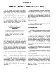
1
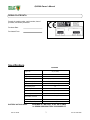
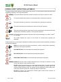
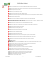
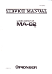
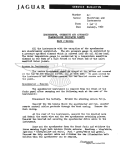
QL2300 Owner’s Manual
BILLY GOAT QL TRUCK LOADER VACUUM
Owner's Manual
QL2300KO
Accessories
INTAKE
EXHAUST
TRAILER
HOSE
REPLACEMENT
KIT
EXHAUST HOSE
KIT
TRAILER QL
Standard on QL
units.
[12"(305mm) x
10' (3.0m)]
[8"(203mm) x 5'
(1.5m)] Quick
release coupler
and flexible steel
hose increases
exhaust
distance.
Heavy duty
spring axle trailer
designed for
towing your QL.
Allows unit to be
mounted for
pickup from rear
and both sides.
P/N 790211
P/N 790114
P/N 790112
Part No 790294
1
Form No F061907B
QL2300 Owner’s Manual
ABOUT THIS MANUAL
THANK YOU for purchasing a BILLY GOAT ® QL Vacuum. Your new machine has been carefully designed and
manufactured to provide years of reliable and productive service. This manual provides complete operating and
maintenance instructions that will help to maintain your machine in top running order. Read this manual carefully
before assembling, operating, or servicing your equipment.
CONTENTS
SERIAL PLATE DATA AND SPECIFICATIONS
3
4-5
GENERAL SAFETY
SOUND AND VIBRATION
6
INSTRUCTION LABELS
7
PACKING CHECKLIST & ASSEMBLY
8-9
OPERATION
9-11
MAINTENANCE
12
TROUBLESHOOTING AND WARRANTY PROCEDURE
13
ILLUSTRATED PARTS & PARTS LISTS
14-15
MAINTENANCE RECORD
Part No 790294
16
2
Form No F061907B
QL2300 Owner’s Manual
SERIAL PLATE DATA
Record the model number, serial number, date of
purchase, and where purchased.
Purchase Date:
Purchased From:
Specifications
QL2300KO
Engine: HP
23 (17.14kW)
Engine: Model
PA-76559
Engine: Type
KOHLER COMMANDER
Engine: Fuel Capacity
Engine: Oil Capacity
8qt. (7.57 L) REMOTE TANK
2.0 qt. (1.9 L), REMOTE OIL FILTER
Total Unit Weight:
399# (181.3 kg)
Max operating slope
0
Overall Height
74” (1.82m)
Overall Width
32” (0.81m)
Overall Length
58” (1.47m)
In compliance with
2000/14/EEC standards
113 dB(a)
Sound at operators position
93 dB(a)
Vibration at operator position
0.02g
BATTERY NOT INCLUDED:
Part No 790294
25
REQUIRES 12 V BATTERY, 40 AH, 240 CCA MIN.
U1 SERIES GROUP BATTERY FOR PROPER FIT
3
Form No F061907B
QL2300 Owner’s Manual
GENERAL SAFETY INSTRUCTIONS and SYMBOLS
The safety symbols shown below are used throughout this manual. You should become familiar with them before
assembling, operating, or servicing this equipment.
This symbol indicates important information that will prevent injury to yourself or others.
This symbol indicates ear protection is recommended when operating this equipment.
This symbol indicates eye protection is recommended when operating this equipment.
This symbol indicates gloves should be worn when servicing this equipment.
This symbol indicates that this manual and the engine manufacturer’s manual should be read
carefully before assembling, operation, or servicing this equipment.
This symbol indicates important information that will prevent damage to your BILLY GOAT
QL VACUUM.
®
This symbol indicates the engine oil level should be checked before operating this
equipment.
Read and make sure you thoroughly understand the following safety precautions before assembling, operating or
servicing this equipment:
READ this manual and the engine manufacturer’s manual carefully before assembling,
operating, or servicing this equipment.
EAR PROTECTION is recommended when operating this equipment.
EYE PROTECTION is recommended when operating this equipment.
BREATHING PROTECTION is recommended when operating this equipment.
EXHAUST from this product contains chemicals known to the State of California to cause
cancer, birth defects or other reproductive harm.
DO NOT operate this equipment on any unimproved forested, brushy, or grass covered land
unless a spark arrester is installed on the muffler as required by Section 4442 of the
California Public Resources Code. The arrester must be maintained in good working order.
Other states may have similar laws. Federal laws apply on federal lands.
DO NOT run engine in an enclosed area. Exhaust gases contain carbon monoxide, an
odorless and possibly fatal poison.
Part No 790294
4
Form No F061907B
QL2300 Owner’s Manual
DO NOT run this equipment indoors or in any poorly ventilated area. Refueling outdoors is recommended.
DO NOT refuel this equipment while the engine is running. Allow engine to cool for at least two minutes before refueling.
DO NOT store gasoline near an open flame.
DO NOT remove gas cap while engine is running.
DO NOT start or operate engine if strong odor of gasoline is present.
DO NOT start or operate engine if gasoline is spilled. Move equipment away from spill until gasoline has completely evaporated.
DO NOT smoke while filling the fuel tank.
DO NOT check for spark with spark plug or spark plug wire removed. Use an approved spark tester.
DO NOT operate engine without a muffler. Inspect muffler periodically and replace if necessary. If equipped with muffler
deflector, inspect deflector periodically and replace if necessary.
DO NOT operate engine with grass, leaves or other combustible material near the muffler.
DO NOT touch muffler, cylinder, or cooling fins when hot. Contact with hot surfaces may cause severe burns.
DO NOT leave equipment unattended while in operation.
DO NOT park equipment on a steep grade or slope.
DO NOT operate equipment with bystanders in or near the work area.
DO NOT allow children to operate this equipment.
DO NOT operate equipment with guards removed.
DO NOT operate equipment near or pick up hot or burning debris or any toxic or explosive materials.
DO NOT operate equipment on slopes greater than specified in Specifications section of this manual.
DO NOT place hands or feet inside nozzle intake, near debris outlet, or near any moving parts.
WARNING: Important
DO NOT use this machine for vacuuming exclusively sand, dust, fine dirt, rock, glass, string like material, grain, rags, cans,
metal, bark or water.
DO NOT start engine without hose and exhaust elbow connected firmly in place to housing and outlet.
DO NOT operate without discharging exhaust into enclosed container.
DO NOT operate with hose or exhaust elbow removed
DO NOT remove hose until engine has been turned off and has come to a complete stop.
DO NOT transport unit without elbow retension cable (item 87) assembled.
DO NOT operate this unit freestanding. Unit must be secured in place during any operation.
ALWAYS remove spark plug wire when servicing equipment to prevent accidental starting.
ALWAYS check fuel lines and fittings frequently for cracks or leaks. Replace if necessary.
ALWAYS keep hands and feet away from moving or rotating parts.
ALWAYS store fuel in approved safety containers.
Part No 790294
5
Form No F061907B
QL2300 Owner’s Manual
SOUND
SOUND LEVEL 93 dB(a) at Operator Position
Sound tests were conducted in accordance with 2000/14/EEC, and were performed on 2-14-2002 under the
conditions listed below.
Sound power level listed is the highest value for any model covered in this manual. Please refer to serial plate on
the unit for the sound power level for your model.
General Conditions:
Temperature:
Wind Speed:
Wind Direction:
Humidity:
Barometric Pressure:
Sunny
50oF (10oC)
15 mph (24.1 kmh)
North
32%
30.06Hg (764 mm Hg)
VIBRATION DATA
VIBRATION LEVEL 0.02g
Vibration levels at the operator’s handles were measured in the vertical, lateral and longitudinal directions using
calibrated vibration test equipment. Tests were performed on 5-7-98 under the conditions listed below.
General Conditions:
Temperature:
Wind Speed:
Wind Direction:
Humidity:
Barometric Pressure:
Sunny
69oF (20.6oC)
8 mph (12.8 kmh)
North
76%
29.71”Hg (755mm Hg)
INTENDED USE
INTENDED USE: This machine is designed for vacuuming leaves, grass clippings and other types of organic litter.
Debris mixed with cans, bottles and small amounts of sand can be vacuumed; however, it is not this machine's
primary purpose. Vacuuming cans, bottles and sand will affect the longevity of your machine.
Do not operate if excessive vibration occurs. If excessive vibration occurs, shut engine off immediately and check
for damaged or worn impeller, loose impeller bolt, loose impeller key, loose engine or lodged foreign objects. Note:
See parts list for proper impeller bolt torque specifications. (See trouble shooting section on page 13).
Part No 790294
6
Form No F061907B
QL2300 Owner’s Manual
INSTRUCTION LABELS
®
The labels shown below were installed on your BILLY GOAT QL Vacuum. If any labels are damaged or missing, replace them before operating
this equipment. Item numbers from the Illustrated Parts List and part numbers are provided for convenience in ordering replacement labels. The
correct position for each label may be determined by referring to the Figure and Item numbers shown.
LABEL DANGER KEEP HANDS
AND FEET AWAY
ITEM #3 P/N 400424
LABEL EAR EYE BREATHING
ITEM# 49 P/N 890254
LABEL READ OWNERS MANUAL
ITEM #50 P/N 830301
LABELWARNING SECURE
ITEM#72 P/N 790232
LABEL EXPLOSIVE FUEL
ITEM # 1 P/N 400268
DANGER FLYING DEBRIS
ITEM #43 P/N 810736
LABEL QL INSTRUCT/WARN
ITEM #18 P/N 790142
LABEL SECURE NOZZLE
ITEM #42 P/N 790301
ENGINE LABELS
KOHLER
THROTTLE CONTROLS
Run/Fast
Part No 790294
Choke/Slow
7
Form No F061907B
QL2300 Owner’s Manual
PACKING CHECKLIST
Your Billy Goat is shipped from the factory in one carton and is completely assembled except for the exhaust elbow,
nozzle, handle loop for nozzle, hose booms, hose bands, hose coupler, hose clamps and related hardware.
READ all safety instructions before assembling unit.
TAKE CAUTION when removing the unit from the box.
PUT OIL IN ENGINE BEFORE STARTING
PARTS BAG &
LITERATURE ASSY
Warranty card P/N- 400972, Owner’s Manual P/N-790294, Declaration of Conformity P/N-790162.
Boxing Parts Checklist
Exhaust Elbow
Nozzle Tray Assembly
Handle Loop Nozzle 811019
Handle Nozzle 811020
Hose Boom Assembly
Nozzle QL 7901492
Hose Clamps 12" (305mm) 790150 Qty. 2
Band Hose Boom 12" (305mm) 790153 Qty. 2
Hose Coupler Assy
Hose 12"x 10' QL 791034
Kohler command pro 23 HP
Parts Bag & Literature Assy P/N 790297
68
Washer 5/16 Fender
8172020 qty. 4
65
59
Nut Lock 1/4-20
8160001 qty. 4
52
Washer 5/16 SAE
8172008 qty. 2
66
For Mounting to a trailer
Washer 1/4 SAE
8172007 qty. 6
Nut Lock 5/16-18
8160002 qty. 4
Screwcap 5/16-18x 1 1/2
8041030 qty. 4
Screwcap 1/4-20x 1 1/2
8041008 qty. 2
60
85
Screwcap 3/8-16x2 3/4
8041057 qty. 4
Nut Lock 3/8-16
8160003 qty. 4
45
Handle Adj. W/Grip
811019 qty. 1
71
Rod Battery Hold Down
790231 qty. 2
Part No 790294
70
NOTE: BATTERY IS
NOT INCLUDED.
REQUIRES 12 V
BATTERY, 40 AH, 240
CCA MIN. U1 SERIES
GROUP BATTERY FOR
PROPER FIT
Parts Bag
Hardware
Washer 3/8 FC
8171004 qty. 8
Bracket Battery QL
790230 qty. 1
8
Form No F061907B
QL2300 Owner’s Manual
ASSEMBLY
1. SECURELY ATTACH unit to the bed of a truck or to a trailer, so that the exhaust discharges into an enclosed container. NOTE:
This unit must be securely mounted to the bed of a truck or to a trailer before operating.
2. ATTACH hose to hose coupler, using hose clamp (item 26)
3. ATTACH hose coupler w/hose to housing intake, which is preassembled to housing front plate, and rotate to lock it in place.
4. ASSEMBLE handle loop nozzle (item 45), to nozzle handle (item 44) using capscrew (item 53), and lock nut (item 60). Adjust
handle loop to desired height and angle and securely tighten in place.
5. ASSEMBLE nozzle handle (item 44), to nozzle (item 25), using screws (item 52), washers (item 66), washers (item 68) and lock
nuts (item 60).
8. ATTACH assembled nozzle to hose using hose clamp (item 26). Before tightening hose clamp, position nozzle handle upward
when hose is stretched to prevent twisting load on hose assembly during operation.
9. ATTACH preassembled hose boom on top of housing using a hitch pin (item 10).
10. ASSEMBLE hose band (item 29) around hose and secure chain between flanges of the hose band using capscrew (item 53)
and lock nut (item 60) Repeat same steps on the other chain. (See ADJUSTING HOSE BOOM on page 11).
11. SECURELY ATTACH exhaust elbow (item 21) capturing both flanges inside the clamp, then firmly tighten the clamp, securing
the elbow to the housing (see MOUNTING on page 10).
12. INSTALL a standard 12 volt lawn and garden battery “U1” series (not included) with at least 240 cold cranking amps and a 40
amp hour rating by using battery bracket QL (item no. 70, hold down rods (item 71), washers (item 70), and lock nuts (item 59).
13. ATTACH red battery cable to + terminal and black battery cable to - terminal.
OPERATION
Like all mechanical tools, reasonable care must be used when operating machine.
Inspect machine work area and machine before operating. Make sure that all operators of this
equipment are trained in general machine use and safety.
PUT OIL IN ENGINE BEFORE STARTING
STARTING
SECURE LOADER OR MOUNT BEFORE STARTING
ENGINE: See engine manufacturer’s instructions for type and amount of oil and gasoline used. Engine must be level when
checking and filling oil and gasoline.
ENGINE SPEED: Controlled by throttle lever on the vac housing. Under normal conditions, operate at minimum throttle to
accomplish your current cleaning task.
INTAKE HOSE: Hose mounting assembly must be properly attached to vac housing and safety switch must be engaged before
engine will start. Note: Any damage to the switch or wiring harness will prevent engine from starting.
THROTTLE: Move throttle control to fast position.
KEY SWITCH: Turn to start position until engine begins to fire, immediately release the key to the run position.
Note: Do not hold key in start position more than 10 seconds per attempt.
IF YOUR UNIT FAILS TO START: See Troubleshooting on page 13. Also see engine owner's manual.
HANDLING & TRANSPORTING:
The unit is equipped with small front wheels to allow for easier transportation to storage. With unit removed from its
mounting, tilt unit forward toward the ground and use wheels to maneuver it into storage area.
HOSE: DO NOT drag the hose with vehicle.
Never lift the machine while the engine is running.
ALWAYS ATTACH NOZZLE TO THE TRAY BEFORE TRANSPORTING UNIT
Part No 790294
9
Form No F061907B
QL2300 Owner’s Manual
Typical on
both sides
MOUNTING: Main unit
GENERAL: Unit must be securely mounted to a trailer, truck bed,
or other similar surface before use. Do not use this unit in a
freestanding position. Unit is not stable until it has been secured in
place.
Secure unit by bolting through the base of the unit and through the
mounting surface using 3/8" dia. bolts, with washers and locking
nuts (see fig. 1)
Fig. 1
MOUNTING: Unit can be mounted in various positions. Figure 2
illustrates the mounting options available when using the optional
trailer (Billy Goat Part no. 790112) available from your Billy Goat
dealer. The unit can be mounted to allow vacuuming from either
side as well as from the rear.
MOUNTING: Exhaust elbow
1) Remove the loose hardware from the clamp assembly so that
there are 4 separate pieces (remaining clamp assembly, two half
plates, and a plate split).
Fig. 2
2) Slide the assembled plates over the housing flange. The
flange should rest between the bottom plate and the plate split.
3) Slide the elbow over the plate spacer and center it in the clamp.
The elbow flange should now be resting on the housing flange
between the plate split and the top plate.
Step 1&2
Housing
4) Insert the other plate split beneath the plate spacer so the holes
align and the plate overlaps the flange on the elbow.
5) Secure the assembly with a plate half on top of the elbow
flange and a plate half on bottom of the housing flange using 3, 1"
carriage bolts and 3 lock nuts (removed hardware in step 1).
Elbow
Step 3
6) Tighten down the clamp with 2, 1 3/4" carriage bolts, 2 knobs,
and 2 lock nuts (removed hardware in step 1).
Step 4
Fig. 5&6
Part No 790294
10
Form No F061907B
QL2300 Owner’s Manual
VACUUMING OPERATION
EXHAUST DIRECTION & DISTANCE: Exhaust direction and distance are controlled by
the angle of the exhaust deflector and by rotation of the exhaust elbow. Adjust the angle
of the exhaust deflector to control the distance that debris is discharged. Typically debris
is aimed to discharge to the rear of the container. The direction of discharge is adjusted by
loosening the knobs on the exhaust elbow clamp and rotating the elbow to the desired
direction.
NOTE: Elbow is heavy. Use caution when adjusting. Never stand directly under the
elbow while adjusting direction of exhaust.
Never adjust exhaust deflector angle or direction of discharge while unit is running.
Never direct exhaust into an area where bystanders may cross the path of the
debris.
INTAKE OPERATION: With machine running and fully assembled, move the nozzle in
sweeping motions over debris. Always allow air to flow into the nozzle along with the
debris. Do not completely block the nozzle when vacuuming, it will reduce performance,
and increase clogging (See figure 3).
For removal of heavier debris, or debris that is stuck to the ground, rock nozzle forward to
concentrate suction power around the debris (See figure 4).
Fig. 3
ADJUSTING HOSE BOOM
Properly adjusting the boom will prevent most hose clogs from occurring and will
maximize vacuum performance by keeping the hose straight and perpendicular
to the housing (see fig. 5).
UNCLOGGING A CLOGGED HOSE
With engine running and unit secured to a trailer, truck bed, or other similar surface,
fully stretch hose in a straight line to dislodge the clog. If the clog will not clear, turn unit
off, and allow engine to come to a complete stop. Remove hose and manually clear
hose clog. NOTE: The clogged debris may be sharp. Always wear durable gloves when
removing clog.
Fig. 4
UNCLOGGING A CLOGGED HOUSING OR EXHAUST ELBOW
Turn engine off and wait for impeller to come to a complete stop. Disconnect spark plug
wires and battery cables. Remove the hose coupler from the housing and determine
where the clog is located. If possible clear the clog through the intake opening. It may
require removal of the intake adaptor (item 33) to allow access to clear the housing. If
clog is in the elbow, carefully remove the elbow. Remove elbow by removing the knobs
on the elbow clamp. Then remove 3 bolts so that the split plate can be taken out.
Finally, the elbow can be removed by sliding it past the remaining attached clamp.
NOTE: Elbow is very heavy. Do not stand directly under elbow during removal.
Danger, the clog may contain sharp materials. Wearing durable gloves, clear the clog.
Reconnect spark plug wire.
HOSE CARE AND TIPS
To increase hose life, periodically rotate hose and reposition nozzle and coupler on
front plate of unit. This increases hose life by keeping hose from wearing only on one
side.
Keep hose as straight as possible and avoid sharp bends during operation for best pickup and to avoid clogs.
Never drag hose. Always remove and store hose before transporting unit.
Store hose straight and flat to maintain flexibility for next use.
THE HOSE IS A REPLACEABLE WEAR ITEM.
Hose
Hose Bands.
Stretch hose out
before clamping
Fig. 5
STORAGE
Turn fuel supply off when unit is not in use. Never store engine indoors or in enclosed poorly ventilated areas with fuel in tank, where
fuel fumes may reach an open flame, spark or pilot light, as on a furnace, water heater, clothes dryer or other gas appliance.
If engine is to be unused for 30 days or more, prepare as follows:
Be sure engine is cool. Do not smoke. Remove all gasoline from carburetor and fuel tank to prevent gum deposits from forming on
these parts and causing possible malfunction of engine. Drain fuel outdoors, into an approved container, away from open flame. Run
engine until fuel tank is empty and engine runs out of gasoline. NOTE: Fuel stabilizer (such as Sta-Bil) is an acceptable alternative in
minimizing the formation of fuel gum deposits during storage. Add stabilizer to gasoline in fuel tank or storage container. Always
follow mix ratio found on stabilizer container. Run engine at least 10 min. after adding stabilizer to allow it to reach the carburetor.
HOSE STORAGE: Storing hose in a covered area, out of sunlight and heat will prolong hose life. Do not store hose where it could
be stepped on or where other objects could crush or damage hose.
Part No 790294
11
Form No F061907B
QL2300 Owner’s Manual
MAINTENANCE
PERIODIC MAINTENANCE
Periodic maintenance should be performed at the following intervals:
Maintenance Operation
Every use
Every 5 hours (daily)
Every 10 Hours
Every 25 Hours
z
Inspect for loose, worn or damaged parts.
Check engine oil and air filter
z
Clean hose
z
Engine (See Engine Manual)
z
Inspect battery for damage or leak
z
Keep engine free of debris
z
Check battery terminal for corrosion
z
Check for excessive vibration
IMPELLER REMOVAL
1. Wait for engine to cool and disconnect spark plugs from the both sides of the engine.
2. Disconnect the negative battery cable (black) (item 12) from the battery.
3. Remove the hose coupler assy from the unit (item 36).
4. Remove the hose boom assembly.
5. Remove the intake housing assembly (item 33) using 1/2" socket and socket wrench to remove (12)
locknuts and washers (item 60 & 63). Be careful to place intake assembly to the side without putting
excess strain on safety switch wire harness
6. Remove impeller bolt and lock washer using 5/8" socket and impact wrench (see fig. 6).
7. Once bolt is removed impeller should slide out freely. If impeller will not slide free on crankshaft,
obtain a 3/4"-10 x 3" bolt and thread it into the nut that is welded onto the center of the impeller and
tighten slowly to push the impeller off the crankshaft.
Note: 3/4"-10 x 3" bolt is included in each impeller replacement kit or the bolt can be ordered from your
local Billy Goat Dealer (part no. 790214).
8. When impeller is free of the engine shaft, align impeller with the opening and pull it straight out of the
housing.
9. Using a new impeller bolt, washer, and lockwasher, reinstall new or repaired impeller in reverse order.
Note: Be sure spacer is in place behind impeller before tightening.
10. Tighten impeller bolt. Torque impeller bolt to [60 Ft. Lbs. (81.4 N.m)].
11. Repeat steps 2 through 5 in reverse order.
12. Reinstall spark plug wires.
Fig. 6
INTERLOCK SYSTEM
With hose coupler installed (as shown in Fig. 8) the switch is open & engine is not grounded out, allowing engine to run.
IGNITION
UNIT
Throttle
stop
Hose must be installed
and switch lever must
engage switch for
engine to start.
Spark plug
INTERLOCK
SW ITCH
Fig. 8
Part No 790294
12
Form No F061907B
QL2300 Owner’s Manual
Troubleshooting
P ro b le m
A b n o rm a l vib ra tio n .
P o s s ib le C a u s e
L o o s e o r o u t o f b a la n c e im p e lle r o r
lo o s e e n g in e
· N o zzle b u rie d in d e b ris . C lo g g e d
h o s e o r e x h a u s t. E x c e s s iv e q u a n tity o f
d e b ris .
B a tte ry is lo w o r d e a d . B a tte ry C a b le is
d is c o n n e c te d o r b a tte ry te rm in a l is
c o rro d e d . H a rn e s s w ire is b a d o r
d is c o n n e c te d fro m in te rlo c k s w itc h .
H o s e n o t in s ta lle d , a llo w in g in te rlo c k
w ire to g ro u n d .
S o lu tio n
C h e c k im p e lle r a n d re p la c e if n e c e s s a ry.
C h e c k e n g in e .
· W ith d ra w n o zzle fro m d e b ris p ile .
U n c lo g h o s e o r e x h a u s t (s e e p g . 1 1 )
A llo w a ir to fe e d d e b ris .
C h a rg e b a tte ry o r re p la c e if th e b a tte ry
d o e s n o t h o ld c h a rg e . C le a n b a tte ry
te rm in a l a n d c a b le th e n re c o n n e c t. In s ta ll
h o s e c o u p le r s e c u re ly to th e u n it a n d
c h e c k w h e th e r in te rlo c k s w itc h is
e n g a g e d b y le v e r. C h e c k h a rn e s s w ire
c o n n e c tio n a n d re p la c e if n e c e s s a ry.
E n g in e w ill n o t s ta rt. (S ta rte r
tu rn s )
· T h ro ttle & / o r s to p s w itc h in o ff
p o s itio n . O u t o f g a s o lin e . B a d o r o ld
g a s o lin e . S p a rk p lu g w ire
d is c o n n e c te d . D irty a ir c le a n e r.
· C h e c k s to p s w itc h e s , th ro ttle , a n d
g a s o lin e . C o n n e c t s p a rk p lu g w ire . C le a n
o r re p la c e a ir c le a n e r. O r c o n ta c t a
q u a lifie d s e rv ic e p e rs o n .
E n g in e is lo c k e d , w ill n o t p u ll
o v e r.
· D e b ris lo c k e d a g a in s t im p e lle r.
E n g in e p ro b le m .
· S e e p g .1 1 , C le a rin g a c lo g g e d im p e lle r
h o u s in g . C o n ta c t a n e n g in e s e rvic in g
d e a le r fo r e n g in e p ro b le m s .
W ill n o t v a c u u m o r h a s p o o r
v a c u u m p e rfo rm a n c e
E n g in e w ill n o t s ta rt. (S ta rte r
d o e s n o t tu rn )
When servicing engine refer to specific manufacturers engine owner's manual. Engine warranty is covered by the
specific engine manufacturer. If your engine requires warranty or other repair work contact your local servicing
engine dealer. When contacting a dealer for service it is a good idea to have your engine model number available
for reference (See table page 3). If you cannot locate a servicing dealer in your area you can contact the
manufacturers national service organization.
To reach:
KOHLER ENGINES: 800-544-2444 www.kohlerengines.com
WARRANTY CLAIM PROCEDURE
Should a BILLY GOAT ® machine fail due to a defect in material and/or workmanship, the owner should make a
warranty claim as follows:
• The machine must be taken to the dealer from whom it was purchased or to an authorized Servicing BILLY
GOAT Dealer.
•
The owner must present the remaining half of the Warranty Registration Card, or, if this is not available, the
invoice or receipt.
•
The Warranty Claim will be completed by the authorized BILLY GOAT Dealer and submitted to their
respective BILLY GOAT Distributor for their territory Attention: Service Manager. Any parts replaced under
warranty must be tagged and retained for 90 days. The model number and serial number of the unit must
be stated in the Warranty Claim.
•
The distributor service manager will sign off on the claim and submit it to BILLY GOAT for consideration.
•
The Technical Service Department at BILLY GOAT will study the claim and may request parts to be
returned for examination. BILLY GOAT will notify their conclusions to the distributor service manager from
whom the claim was received.
•
The decision by the Technical Service Department at BILLY GOAT to approve or reject a Warranty Claim is
final and binding.
For online product registration go to www.billygoat.com
Part No 790294
13
Form No F061907B
QL2300 Owner’s Manual
PARTS DRAWING QL2300KO
Part No 790294
14
Form No F061907B
QL2300 Owner’s Manual
PARTS LIST
ITEM
NO.
1
2
3
4
5
6
7
8
9
10
11
12
13
14
15
16
17
18
19
20
21
22
23
24
25
26
27
28
29
30
31
32
33
34
35
36
37
38
39
40
41
42
43
44
45
46
47
48
49
50
PART
NO.
400268
400339
400424
850132
500267
500282
790275
790129
790263
790271
790132
790133
790134
510185
790307
790293
790103-S
790142
790143-S
LABEL HOT ENGINE
KNOB
LABEL OPEI WARNING
WASHER TWISTED LOCK 7/16"
GRIP HANDLE
STRAIN RELIEF HEYCO 1244
ENGINE 23 HP HORIZ. KOHLER COMMAND PRO
LINE FUEL QL
TUBE BOOM ARM QL
PIN 5/8 X 15.5 QL
CABLE BATTERY RED 26"
CABLE BATTERY BLACK 10"
CLAMP FUEL LINE
BUSHING NYLON 0.625
SCREWCAP 7/16-14 x 2" GR. 5
PLATE RING SPACER QL KOHLER
IMPELLER 16" x 1.12" ASSY QL (INCL. 4,32,84)
LABEL QL INSTRUCT/WARN
BASE ENGINE ASSY QL(INCLUDES 72)
1
4
3
5
4
1
1
1
1
1
1
1
2
5
4
1
1
1
1
790145-S
790255-S
790147
791034
790149
790150
790270
790152
790153
790267
790291
500188
790288
890440
790305
790289
811123
ELBOW 8" ASSY QL(INCLUDES 2,3,43)
CLAMP ASSEMBLY
DEFLECTOR EXHAUST QL
HOSE 12" x 10'
NOZZLE INTAKE 12" FORMED
CLAMP HOSE 12"
BOOM HINGE WA QL
SPRING BOOM QL
BAND HOSE BOOM 12" FORMED
ARM BOOM WA QL
BOLT EYE 3/8" x 2.5"
SCREWCAP 7/16-20X2" GR.8 [TORQUE 60 ft.lb. (81.4Nm)]
INTAKE HOUSING ASSY (INCL. 3,6,34,35,37,55,60,63,69)
PLUNGE SWITCH
HARNESS WIRE ASSY QL23 KO
HOSE INTAKE ASSY QL (INCL. 2,38,48,92)
PLUG 3/4"
1
1
1
1
1
2
1
2
2
1
2
1
1
1
1
1
1
LINKGAGE 1/4" CHAIN
CHAIN 5 LINKS
CHAIN HANG HOSE QL
LABEL WARNING NOZZLE
LABEL FLYING DEBRIS
HANDLE NOZZLE W/ GRIP
HANDLE ADJ. NOZZLE W/ GRIP
BOLT EYE 3/8" X 5"
LABEL SECURE NOZZLE
PLUG RD 1"
LABEL EAR EYE BREATHE
LABEL READ
2
1
1
1
2
1
1
2
1
4
1
1
811160
790306
790189
790301
810736
811020
811019
790290
811215
890132
890254
890301
DESCRIPTION
Part No 790294
QTY
ITEM
NO.
51
52
53
54
55
56
57
58
59
60
61
62
63
64
65
66
67
68
69
70
71
72
73
74
75
76
77
78
79
80
81
82
83
84
85
86
87
88
89
90
91
92
93
15
PART
NO.
*8024044
*8041030
*8041031
790310
*8024050
*8041051
BOLT CARRAIGE 5/16-18 x 2
SCREWCAP 5/16-18 x 1 1/2
SCREWCAP 5/16-18 x 1 3/4
GROMNET 1" x 3/4" I.D.
BOLT CARR. 5/16 - 18 x 3 1/2
SCREW CAP 3/8 - 16x 1 1/4
2
4
4
4
1
4
*8122082
*8160001
*8160002
*8160003
SCREW SM 1/4 x 3/4
NUT LOCK 1/4"-20 HEX Z/P
NUT LOCK 5/16-18
NUT LOCK 3/8
5
8
21
10
*8171003
*8171004
*8172007
*8172008
*9201125
*8172020
790298
790230
790231
790232
790105
790285
790311
400502
790303
8177011
790240
*8041026
790258
790259
790204
850443
8041008
8041004
8171002
8024040
790254
790253
790252
8161041
8024040
WASHER 5/16 FLAT CUT
WASHER FLAT 3/8
WASHER 1/4 SAE
WASHER 5/16 SAE
KEY 1/4 x 2 3/4
WASHER 5/16 FENDER
DOOR FLAPPER INTAKE QL23
BRACKET BATTERY QL
ROD BATTERY HOLD DOWN
LABEL WARNING SECURE
HOUSING ASSY QL
TRAY NOZZLE WA QL23KO
SPACER - ENGINE
WASHER LOCK TWISTED TOOTH
BUNGEE CORD BLACK 14"
WASHER LOCK TWISTED TOOTH
90 DEGREE ELBOW 1/8" NPT MALE X 1/4"
SCREWCAP 5/16-18 X 3/4 HCS ZP
CAP TANK FUEL 3 GAL
TANK FUEL 3 GAL ASSY
U-BOLT 3/8" -16 - X 3
WASHER PLATE IMPELLER
SCREWCAP 1/4-20 x 1 1/2
SCREWCAP 1/4-20 X 3/4" HCS ZP
WASHER 1/4
CARRIAGE BOLT 5/16x18x1
PLATE CLAMP SPLIT
PLATE CLAMP SPACER
PLATE CLAMP HALF
LOCK NUT 5/16-18 THIN ZP
BOLT CARRIAGE 5/16-1" ZP
22
10
6
2
1
4
1
1
2
3
1
2
1
4
1
4
1
4
1
1
1
1
1
2
14
2
2
1
4
11
6
DESCRIPTION
QTY
Form No F061907B
QL2300 Owner’s Manual
MAINTENANCE RECORD
Date
Part No 790294
Service Performed
16
Form No F061907B