1
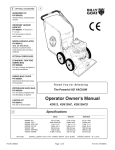
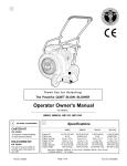
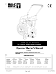
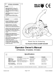
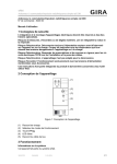
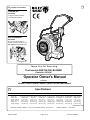
2
1
OPTIONAL ACCESSORIES
CASTER KIT
P/N 430291
To improve maneuverability
on hard paved surfaces.
HOLD DOWN KIT
P/N 430299
For use on truck or trailer to
provide quick hold down for your
QB. (QB884H/1004/1304H only)
Thank You for Selecting
The Powerful QUIET BLOW® BLOWER
Patent No. 6253416
Operator Owner's Manual
For Models:
QB554HC, QB654, QB884H, QB994S, QB1004, QB1304H,QB1304HBW
Specifications
3
QB554HC
Engine: HP
Engine:Type
Engine: Fuel cap.
Engine: Oil Cap.
Weight: Unit
Weight: Shipping
QB654
QB884H
QB994S
QB1004
QB1304H
QB1304HBW
5.0 HP (3.73 kW) 6.5 HP (4.85 kW) 8.0 HP (5.97 kW) 9.0 HP (6.7 kW) 10.0HP (7.45kW) 13.0HP (9.69kW) 13.0HP (9.69kW)
HONDA OHC
B&S OHV
HONDA OHV
SUBARU OHV B & S INTEK I/C HONDA OHV
HONDA OHV
2.1 qt. (2.0 L)
3.0 qt. (2.9 L)
6.4 qt. (6.1 L)
6.4 qt. (6.1 L)
4.0 qt. (3.8 L)
7.4 qt. ( 7.0 L)
7.4 qt. ( 7.0 L)
0.63 qt. (0.6 L)
0.63 qt. (0.6 L)
1.16 qt. (1.1 L)
1.05 qt. (1.0 L)
0.875 qt.(0.8L)
1.2 qt.(1.13L)
1.2 qt.(1.13L)
98 # (44.5 Kg)
104 # (47.3 Kg) 136 # (61.7 Kg) 129 # (58.6 Kg) 136 # (61.7 Kg) 152 # (68.9 Kg) 162 # (73.6 Kg)
115 # (52.3 Kq) 121 # (55.0 Kq) 155 # (70.3 Kq) 148 # (67.3 Kq) 155 # (70.3 Kq)
169 # (76.7 Kg) 179 # (81.4 Kg)
(International only)
UNIT SIZE: OVERALL LENGTH: 51.75"(1.31m) OVERALL WIDTH 28.5" (0.72m)
Part No. 430316
Page 1 of 12
OVERALL HEIGHT
39" (0.99m)
Form No. F012203A
5
IN THE INTEREST OF SAFETY
BEFORE STARTING ENGINE, READ AND UNDERSTAND THE “ENTIRE OPERATOR'S MANUAL &
ENGINE MANUAL.”
THIS SYMBOL MEANS WARNING OR CAUTION. DEATH, PERSONAL INJURY AND/OR PROPERTY
DAMAGE MAY OCCUR UNLESS INSTRUCTIONS ARE FOLLOWED CAREFULLY.
WARNING!
The engine exhaust from this product contains chemicals known to the State of California to cause
cancer, birth defects or other reproductive harm.
WARNING: DO NOT
1. DO NOT run engine in an enclosed area.
Exhaust gases contain carbon monoxide, an
odorless and deadly poison.
2. DO NOT place hands or feet near moving
or rotating parts.
3. DO NOT store, spill or use gasoline near
an open flame, or devices such as a stove,
furnace, or water heater which use a pilot
light or devices which can create a spark.
4. DO NOT refuel indoors where area is not
well ventilated. Outdoor refueling is recommended.
5. DO NOT fill fuel tank while engine is
running. Allow engine to cool for 2 minutes
before refueling. Store fuel in approved
safety containers.
6. DO NOT remove fuel tank cap while
engine is running.
7. DO NOT operate engine when smell of
gasoline is present or other explosive
conditions exist.
13. DO NOT tamper with governor springs,
governor links or other parts which may
change the governed engine speed.
14. DO NOT tamper with the engine speed
selected by the engine manufacturer.
15. DO NOT check for spark with spark plug
or spark plug wire removed. Use an
approved tester.
16. DO NOT crank engine with spark plug
removed. If engine is flooded, place throttle
in “FAST” position and crank until engine
starts.
17. DO NOT strike flywheel with a hard
object or metal tool as this may cause
flywheel to shatter in operation. Use proper
tools to service engine.
18. DO NOT operate engine without a
muffler. Inspect periodically and replace, if
necessary. If engine is equipped with
muffler deflector, inspect periodically and
replace, if necessary, with correct deflector.
21. DO NOT touch hot muffler, cylinder, or
fins because contact may cause burns.
22. DO NOT run engine without air cleaner
or air cleaner cover.
23. DO NOT operate during excessive
vibration!
24. DO NOT leave machine unattended
while in operation.
25. DO NOT park machine on a steep grade
or slope.
WARNING: DO
1. ALWAYS DO remove the wire from the
spark plug when servicing the engine or
equipment TO PREVENT ACCIDENTAL
STARTING.
2. DO keep cylinder fins and governor parts
free of grass and other debris
which can
affect engine speed.
3. DO pull starter cord slowly until resistance
is felt. Then pull cord rapidly to avoid
kickback and prevent hand or arm injury.
19. DO NOT operate engine with an
accumulation of grass, leaves, dirt or other
combustible material in the muffler area.
4. DO examine muffler periodically to be
sure it is functioning effectively. A worn or
leaking muffler should be repaired or
replaced as necessary.
5. DO use fresh gasoline. Stale fuel can gum
carburetor and cause leakage.
11. DO NOT choke carburetor to stop engine.
Whenever possible, gradually reduce engine
speed before stopping.
20. DO NOT use this engine on any forest
covered, brush covered, or grass covered
unimproved land unless a spark arrester is
installed on the muffler. The arrester must
be maintained in effective working order by
the operator. In the State of California the
above is required by law (Section 4442 of
the California Public Resources Code).
Other states may have similar laws. Federal
laws apply on federal lands.
12. DO NOT run engine at excessive speeds.
This may result in injury & /or damage
7
to unit.
SOUND
8. DO NOT operate engine if gasoline is
spilled. Move machine away from the spill
and avoid creating any ignition until the
gasoline has evaporated.
9. DO NOT transport unit with fuel in tank.
10. DO NOT smoke when filling fuel tank.
6
TABLE OF CONTENTS
SAFETY INSTRUCTIONS
GENERAL SAFETY
ASSEMBLY
LABELS
PARTS BAG & CONTROLS
OPERATION
MAINTENANCE
PARTS DRAWING & LIST
TROUBLESHOOTING
WARRANTY PROCEDURE
2
3
3
4
4
5-6
7-9
10-11
12
12
NOTE: Sound power level listed is the highest value for any model in this manual.
Please refer to serial plate on the unit for the sound power level for your model.
Sound level of 97 dBA at operator position
GENERAL CONDITION:
112 dB
(QB1304 MODEL)
WIND SPEED:
8. Inspect machine and work area before
starting unit.
Sunny
60° F (15.6° C)
10 MPH (16.1 kmh)
VIBRATION
VIBRATION LEVELS 3.2 g
Vibration levels at the operators handles were
measured in the vertical, lateral, and longitudinal
directions using calibrated vibration test equipment.
Tests were performed on 04/10/2000 under the
conditions listed:
GENERAL CONDITION:
TEMPERATURE:
WIND SPEED:
WIND DIRECTION:
North
WIND DIRECTION:
HUMIDITY:
32 %
HUMIDITY:
BAROMETRIC PRESSURE:
Part No. 430316
7. Follow engine manufacturer operating
and maintenance instructions.
8
Sound tests conducted were in accordance with 2000/14/EEC and
were performed on 2/16/2002 under the conditions listed:
TEMPERATURE:
6. DO check fuel lines and fittings frequently
for cracks or leaks. Replace if necessary
29.95" Hg (761mm Hg)
Page 2 of 12
BAROMETRIC PRESSURE:
Sunny
60° F (15.6° C)
9 MPH (14.5 kmh)
South East
49 %
29.94" Hg (760mm Hg)
Form No. F012203A
9
GENERAL SAFETY
For your safety and the safety of others, these
directions should be followed:
Do not operate this machine without first reading
owner's manual and engine manufacturer's manual.
Use of Ear Protection is recommended while
operating this machine.
Use of Eye and breathing protection is recommended when using this machine, especially in
dry and dusty conditions.
10
ASSEMBLY
Read all safety and operating instructions
before assembling or starting this unit.
PUT OIL IN ENGINE BEFORE STARTING
Your Billy Goat is shipped from the factory in one carton,
completely assembled except for the upper handle assembly,
handle brace, plate deflector and throttle control.
1.Install front exhaust wire loop(Item 55) across upper handle and
slide wire loop to lowest possible position on upper handle.
Install upper handle (Item 28), to preassembled lower handle
(item 29) by sliding the upper over and down the outside of the
lower handle. Pull recoil handle from the engine and place it
between rope guides (Item 13). Using screw (Item 22) & lock nut
(Item 32) to install upper handle to lower handle. NOTE: Install
rope guide on the left hand side for the Honda unit and right hand
side for the Briggs & Stratton unit (See fig below for the pictorial
11
·DO NOT place hands or feet inside air intake opening, near
exhaust outlet or near any moving parts.
·DO NOT start engine without deflector attached to exhaust outlet.
·DO NOT direct exhaust outlet toward any bystanders.
·DO NOT operate this equipment without first inspecting
work area.
·DO NOT operate this equipment during excessive vibration.
·DO NOT start engine without housing front plate attached.
·DO NOT operate this machine on slopes greater than 20%.
·DO NOT blow any hot or burning debris, or any toxic or
explosive material.
·DO NOT allow children to operate this equipment.
example). Finish installing the other side of the upper handle assembly using
screw (Item 17) and lock nut (Item 32).
2. Install front of handle brace (Item 30), to blower housing using
one screw (Item 17), one washer (Item 58) and one lock nut (item 32).
Install rear of handle brace (item 30) to upper handle vibration mounts using
two lock nuts (item 32). Hand tighten only. NOTE: 13 hp Honda models will
have an offset bracket (item 65) installed at the front of the housing. Connect
the handle brace (Item 30) to the bracket (Item 65) on 13 hp models.
3. Securely tighten all hardware listed above in steps 1 thru 2.
4. Remove four lock nuts from the front plate and use them to attach the front
wheel bracket (Item 27). Using spacer (Item 18), washer (Item 19), and Lock
Nut (Item 16) to attach Front wheel (Item 23) onto the front wheel bracket.
5. (QB1304HBW only) Your unit was shipped with the rear wheels removed.
To complete assembly of your unit you must remove the clip at each end of
the rear axle and slide the rear wheel onto the axle, leaving all spacers and
washers in place between the frame and wheel. Re-install the clip at the end
of the axle to secure the wheel in place.
6.Connect spark plug wire.
PACKING CHECKLIST
Boxing Checklist
Check
These items should be included in your carton. If
any of these parts are missing, contact your dealer.
Front Exhaust
Director
430315 (8/10/13 hp)
430370 (5/6.5 hp)
Check
Wire Director
Mount 430391
Check
Check
Parts Bag
& Literature
Assy
Check
Check
Handle Upper
Assembly
400957
Handle Brace
400951
Parts Bag &
Literature Assy
430334
Per Model
Briggs & Stratton
6.5 or 10 HP
Check
Engine
Manual
Per Model
Honda 5, 8, or 13 hp
Check
Subaru 9 hp
Check
Denotes parts found in
Parts Bag Assembly
(shown on page 4).
Bracket Front
Wheel 430270
Check
Front Wheel
430271
Part No. 430316
Page 3 of 12
Form No. F012203A
PARTS BAG & LITERATURE ASSY
12
13
CONTROLS
PARTS BAG ASSEMBLY CHECKLIST
Screw Cap
5/16-18 x 1 1/4
8041029 Qty. 1
14
Check
Screw Cap
5/16-18 x 1 3/4
8041031
Qty. 1 (8/10/13 hp)
Qty. 2 (5/6.5 hp)
17
Throttle Control /
Gust Control
Literature Checklist
19
Washer 1/2 SAE
8172011 Qty. 1
Owner's
Manual
430316
Start
Quiet Blow fi
Series Blowers
58
Stop
STOP
START
22
Check
Washer 5/16 FLAT CUT
8171003 Qty. 1
Screw Cap 5/16-18 x 2 1/2
8041034 Qty. 1 (8/10/13 hp) ONLY
Literature
Parts Bag
STOP
START
430341
32
24
1
2
1
1
Screw Cap 3/8-16 x 3 3/4
8041061 Qty. 1
Nut Lock 5/16-18
8160002 Qty. 4
Spacer 1/2 OD x
3.062" Qty. 1
18
Check
55
Warranty
Card
400972
TO LOCK IN MIDDLE
SLIDE LEVER TO RIGHT TO LOCK
AIR DIRECTOR IN MIDDLE POSITION
TO UNLOCK
SQUEEZE THE LEVER TO UNLOCK
AIR DIRECTOR FROM MIDDLE
POSITION
TO LOCK IN MIDDLE
SLIDE LEVER TO RIGHT TO LOCK
AIR DIRECTOR IN MIDDLE POSITION
TO UNLOCK
SQUEEZE THE LEVER TO UNLOCK
AIR DIRECTOR FROM MIDDLE
POSITION
Part No:
430388
13
Nut Lock 5/16-18 Thin
8161041 Qty. 1
Check
16
20
INSTRUCTION LABELS
Honda
5 HP
EU Declaration
of Conformity &
EU Distributor
List 430189
Honda
8 & 13,
Subaru
9 HP
Briggs &
Stratton
ENGINE LABELS
15
These labels should be included on your Blower. If any of
these labels are damaged, replace them before putting this
equipment into operation. Item and part numbers are given to
help in ordering replacement labels.
Briggs & Stratton
ON
RUN
CHOKE
400268
WARNING
EXPLOSIVE FUEL
STOP ENGINE AND ALLOW T O
COOL BEFORE REFUELING.
OFF
Label Do Not Fill While
Engine Is Hot
Item 11 Part No.400268
THIS ENGINE EQUIPPED WITH
LOW OIL SENSOR, IF ENGINE WILL
NOT START, CHECK OIL LEVEL
Label Danger Keep Hands and Feet Away
Item 41 Part No.400424
Read and follow Operating
Instructions before running engine.
Gasoline is flammable. Allow engine
to cool at least 2 minutes before fueling.
Engines emit carbon monoxide,
DO NOT run in enclosed area.
890254
Label Read Owner's Manual
Item No. 59 Part No. 890301
Label Ear Eye Breathing
Item No. 63 Part No. 890254
Label Danger Flying Material
Item No. 44 Part No. 810736
Honda
READ OWNER’S MANUAL BEFORE OPERATION.
LIRE LE MANUEL D UTILISATEUR AVANT USAGE.
VOR INBETRIEBNAHME UNBEDINGHT BEDIENUNGSANLEITUNG DURCHLESEN.
NO UTILIZAR SINANTES NO HABER LEIDO EL MANUAL
PART NO: 430400
DANGER
810736
14
Part No:
430351
Part No:
430333
Nut Lock 3/8-16
8161042 Qty. 1
Cable Ty 1"
900407 Qty. 3
TO LOCK IN MIDDLE
SLIDE LEVER TO RIGHT TO LOCK
AIR DIRECTOR IN MIDDLE POSITION
TO UNLOCK
SQUEEZE THE LEVER TO UNLOCK
AIR DIRECTOR FROM MIDDLE
POSITION
4
Wire Mount
Director
430391 Qty. 1
Rope Guide
830533 Qty. 2
(8/10/13 hp)
ONLY
2
2
Label Patent QB Air Director
Part No. 430400
HONDA MOTOR CO. , L TD. MADE IN JAPAN
OIL ALERT
PULL THEN SLIDE TO LOCK
WHEN OIL LEVEL LOW,
ENGINE STOPS IMMEDIATELY.
Label Lever QB Item No. 46
Part No. 430363
Part No. 430316
Page 4 of 12
Form No. F012203A
16
OPERATION
Like all mechanical tools, reasonable care must
be used when operating machine.
Inspect machine work area and machine before operating. Make sure that all operators of this equipment are
trained in general machine use and safety.
INTENDED USE: This machine is designed for cleaning
outdoor surfaces, where the debris can be effectively
blown into a consolidated area for convenient pickup and
removal.
Side Discharge Up Position
This position allows air to be directed upward during use to avoid
blowing debris into cars or other structures, or to avoid blowing
landscaped areas that would be damaged by the high speed air.
This position also allows operator to maneuver the machine
relative to the work area without disturbing the debris.
Do not operate if excessive vibration occurs. If excessive
vibration occurs, shut engine off immediately and check for
damaged or worn impeller, loose impeller bolt, loose
impeller key, loose engine or lodged foreign objects. Note:
See parts list for proper impeller bolt torque specifications.
(See trouble shooting section on page 12).
PUT OIL IN ENGINE BEFORE STARTING
16.1
STARTING
ENGINE: See engine manufacturer’s instructions
for type and amount of oil and gasoline used.
Engine must be level when checking and filling oil and
gasoline.
FUEL VALVE: Move fuel valve to "ON" position (when
provided on engine).
STOP SWITCH: Located on the engine. "ON" position.
CHOKE: Operated with choke lever on side of engine .
THROTTLE: Controlled by throttle lever on the handle. Move
remote throttle control to fast position. Pull starting rope to
start engine.
ENGINE SPEED: Under normal conditions, operate at
minimum throttle to accomplish your current cleaning task.
IF YOUR UNIT FAILS TO START:
See Troubleshooting on page 12.
16.2
Side Discharge Straight Position
This position directs the air parallel to the ground for the
majority of blowing operations. The hand control allows the
operator to lock the air stream in this straight out position. To
LOCK the air in position simply pull back on the lever and pull
the lever sideways to the right until the lock engages. See
instruction label on the control.
Slide over to right to
lock in middle position
HANDLING & TRANSPORTING:
Using two people to lift machine is recommended. Lift holding the
handle and handle brace. Secure in place during transport.
16.3
BLOWING OPERATION
Your Billy Goat blower is equipped with a remote exhaust
director to allow the operator to direct the air stream up or down
as required to assist in moving debris. This feature is extremely
useful when debris has piled up to the point that it cannot be
blown any farther. The air stream can be directed upward to
blow the top of the debris pile over and allow the operator to
continue moving more debris farther.
Part No. 430316
Page 5 of 12
Form No. F012203A
16
OPERATION
continued
Side Discharge Down Position
This position directs the air stream down at the ground to
allow the operator to deliver the maximum power to debris
that is stuck or difficult to remove. This position is also
very useful for cleaning out cracks and expansion joints in
pavement.
16.4
ADJUSTING AIR DIRECTOR
When you lock the lever, the default position of air director is in the
middle or straight out. If you want to raise or lower air director lock
position you must adjust the threaded fitting on the cable.
Note: You will not get full range of motion of air director If
you raise or lower default locking postion.
Raise Lock Position
1. Lock the air director in
place at the handle by
pulling on the lever then
slide it over to right.
2. Loosen the top nut on the
threaded cable fitting until
the air director position is
satisfactory.
3. Tighten the bottom nut.
Lower Lock Position
Front Discharge Position
The removable front discharge adapter can be slipped
on to direct the air stream forward. This option is
extremely useful for cleaning out long cracks in pavement or for cleaning under bushes or building overhangs.
1. Lock the lever at the
handle by pulling on the
lever then slide it over to
right.
2. Loosen the bottom nut on
the threaded cable fitting
and back it off 1/4 inch.
3. Pull the threaded cable
fitting up while pushing down
on the air director then
check for air director
position.
4. Loosen or tighten the same bottom nut then repeat step 3 until the air
director position is satisfactory.
5. Tighten the top nut.
16.5
STORAGE
Never store engine indoors or in enclosed poorly ventilated areas
with fuel in tank, where fuel fumes may reach an open flame, spark or
pilot light, as on a furnace, water heater, clothes dryer or other gas
appliance.
If engine is to be unused for 30 days or more, prepare as follows:
Remove all gasoline from carburetor and fuel tank to prevent gum
deposits from forming on these parts and causing possible malfunction
of engine. Drain fuel outdoors, into an approved container, away from
open flame. Be sure engine is cool. Do not smoke. Run engine until
fuel tank is empty and engine runs out of gasoline.
NOTE: Fuel stabilizer (such as Sta-Bil) is an acceptable alternative
in minimizing the formation of fuel gum deposits during storage. Add
stabilizer to gasoline in fuel tank or storage container. Always follow
mix ratio found on stabilizer container. Run engine at least 10 min.
after adding stabilizer to allow it to reach the carburetor.
Part No. 430316
Page 6 of 12
Form No. F012203A
17
MAINTENANCE
Use only a qualified mechanic for
any adjustments, disassembly or any
kind of repair .
WARNING: TO AVOID PERSONAL INJURY, ALWAYS
TURN MACHINE OFF, MAKE SURE ALL MOVING
PARTS COME TO A COMPLETE STOP.
17.3
1. Wait for engine to cool and disconnect spark plug.
2. Remove front wheel (item 23),and front wheel bracket
(item 27).
3. Remove housing front plate (item 4), by removing nine
(9) screws (item 12), around outside of front plate.
4. Remove impeller bolt and lock washer.
DISCONNECT SPARK PLUG WIRE
BEFORE SERVICING UNIT.
Note: DO NOT pull or pry on impeller blades.
Also, DO NOT remove the 3 nuts securing the
impeller to the hub.The complete impeller assembly must be removed as a nut.
ENGINE: See engine manufacturer
operator's instructions.
RECONNECT SPARK PLUG WIRE AND
GUARDS BEFORE STARTING ENGINE.
17.1
MAINTENANCE SCHEDULE
Follow these hourly maintenance intervals.
Maintenance Operation
Every Use Every 5 hrs. or
(Daily)
IMPELLER REMOVAL
Every 25
hrs.
Engine (See Engine Manual)
5. Pull on center hub backplate area only of impeller. If
impeller slides off freely, proceed to (step 8).
6. Place two crowbars between center hub backplate area
of impeller and housing on opposite sides. Carefully pry
impeller away from engine until it loosens. Using a penetrating oil can help loosen a stuck impeller.
7. If the impeller does not loosen, obtain a 1” (25.4mm)
longer bolt of the same diameter and thread type as the
impeller bolt. Thread longer bolt by hand into the crankshaft
until bolt bottoms. Using a suitable gear or wheel puller
against the bolt head and the impeller back-plate (near the
blades), remove impeller from shaft.
8. Reinstall new impeller in reverse order of removal.
9. Tighten impeller bolt. Torque impeller bolt (see parts list
on page 7 for proper impeller bolt torque specifications).
Check for excessive vibration
Inspect for loose parts
17.4
TIRE AIR PRESSURE
Inspect for worn or damaged parts
Check at regular intervals and maintain.
Rear Tires - 24 Psi (17 kPa).
Front Tire - 50 Psi (35 kPa).
Lubricate wheels
17.2
ENGINE
When servicing engine refer to specific manufacturers engine
owner's manual. All engine warranty is covered by the specific
engine manufacturer. If your engine requires warranty or other
repair work contact your local servicing engine dealer. When
contacting a dealer for service it is a good idea to have your
engine model number available for reference(See table page 11).
If you can not locate a servicing dealer in your area you can
contact the manufacturers national service organization.
To reach:
Briggs & Stratton: 800-233-3723
American Honda: 800-426-7701
Subaru America: 800-277-6246
Part No. 430316
Page 7 of 12
Form No. F012203A
17
MAINTENANCE
continued
AIR FILTER COVER REMOVAL INSTRUCTION (BRIGGS AND STRATTON)
Removing the air filter cover (for air filter change and throttle control installation)
1. Disconnect spark plug wire.
2. Remove the locknut and the screwcap holding the front part of the handle brace.
3. Remove the screw from the front of the air filter cover (fig 1).
4. Remove the air filter cover by leaning the top of the cover back towards the lower handle and lifting it up (fig 2).
Figure 2
Figure 1
Installing the air filter cover
1. Install air filter on the engine. (fig 3).
2. Slide the bottom of the air filter cover in place and tilt the cover towards the engine (fig 4 & 5)
Note: You must line up the tabs on bottom of the cover to the slots on the air filter housing.
3. Attach the screw (fig 6)
4. Reconnect the front part of the handle brace.
5. Reconnect spark plug wire.
Part No. 430316
Figure 3
Figure 4
Figure 5
Figure 6
Page 8 of 12
Form No. F012203A
17
MAINTENANCE
continued
AIR FILTER COVER REMOVAL INSTRUCTION (HONDA 8 and 13 H.P.)
Removing the air filter cover (for air filter change and throttle control installation)
1. Disconnect spark plug wire.
2. Remove the wingnut on the top of the air cleaner cover (fig. 1).
3. Remove the air filter cover by leaning the air cleaner cover towards the left side of the machine then remove (fig 2).
Figure 2
Figure 1
THROTTLE CONTROL CABLE INSTALLATION
Briggs & Stratton Engine
1. Remove clamp screw and cable
clamp from front of engine (clamp
must be on the left side on engine
control lever. if clamp is on the
right side, change to the left).
2. Insert "z" end of throttle cable
into hole in engine lever, then
secure cable with clamp screw and
cable clamp on the left side of the
engine control lever (DO not
tighten the screw) (Fig 3).
3. Route throttle cable behind
cover through the slots
provided(Fig 4).
4. Put throttle lever in the "fast"
position at the handle.
6. Pull throttle control wire and
casing back then tighten clamp
screw. DO not over tighten (Fig 5).
Figure 3
Figure 4
Honda Engine
1. Remove air cleaner cover by removing wing nut at the top of cover.
2. Remove cable clamp and screw from engine control lever.
3. Attach "z" end of throttle cable through hole in engine control lever.
4. Replace cable clamp and screw but do not tighten.
5. Put throttle lever in "stop" position at the handle.
6. Pull throttle control wire and casing back then tighten clamp screw.
DO not over tighten.
NOTE: If throttle control seems stiff, it may be necessary to
loosen the 10mm locknut on the engine control lever about 1/2 turn
7. Replace air cleaner and wing nut.
Part No. 430316
Page 9 of 12
Figure 5
Form No. F012203A
18
PARTS DRAWING
QB554HC, QB654, QB884H,
QB994S, QB1004, QB1304H,
QB1304HBW
Part No. 430316
Page 10 of 12
Form No. F012203A
(International only)
19
ITEM
PARTS
LIST
1
DESCRIPTION
QB554HC
QB654
QB884H
PART NO QTY
QB994S
PART NO QTY
QB1004
PART NO QTY
QB1304H
PART NO QTY
QB1304HBW
PART NO QTY
PART NO
QTY
PART NO
QTY
ENGINE - 13HP HONDA
-
-
-
-
-
-
-
-
-
-
430366
1
430366
1
ENGINE - 10 HP BRIGGS & STRATTON INTEK
-
-
-
-
-
-
-
-
430352
1
-
-
-
-
ENGINE - 8 HP HONDA
-
-
-
-
400937
1
-
-
-
-
-
-
-
-
430272
1
-
-
-
-
-
-
-
-
-
-
-
-
ENGINE - 5.0 HP HONDA
ENGINE - 9.0 HP SUBARU OHV
-
-
-
-
-
-
430413
1
-
-
-
-
-
-
ENGINE - 6.5 HP BRIGGS & STRATTON
-
-
430372
1
-
-
-
-
-
-
-
-
-
-
2
WASHER LOC K 5/16 TWISTED TOOTH
800177
2
800177
2
800177
2
800177
2
800177
2
800177
2
800177
2
3
GUST DIRECTOR QB
430369
1
430369
1
430314
1
430314
1
430314
1
430314
1
430314
1
4
PLATE FRONT & GRILL ASSY
430182
1
430182
1
430182
1
430182
1
430182
1
430182
1
430182
1
5
IMPELLER ASS’Y
430276
1
400922
1
400965
1
400965
1
400965
1
400965
1
400965
1
6
KEY SQUARE 1/4 X 2 1/4
1
-
-
*9201123
1
*9201123
1
*9201123
1
*9201123
1
*9201123
1
*9201123
KEY SQUARE 3/16 x 1 3/4"
9201084
1
-
-
-
-
-
-
-
-
-
-
-
-
7
LABEL C ONTROL QB HONDA
430388
1
-
-
430333
1
430333
1
-
-
430333
1
430333
1
430351
1
-
-
-
-
430351
1
-
-
-
-
8
AXLE
430181
1
430181
1
430181
1
430181
1
430181
1
430181
1
430394
1
9
WASHER LOC K 7/16 TWISTED TOOTH
850132
1
-
-
850132
1
850132
1
850132
1
-
-
-
-
WASHER LOC K 3/8 TWISTED TOOTH)
-
-
400502
1
-
-
-
-
-
-
400502
1
400502
1
LABEL C ONTROL QB B&S
10
SCREW CAP 7/16-20 x 1-1/4 HEX. HD GR. 5 (TORQUE 58 FT LBS)(78 N.m)
-
-
-
-
800554
1
800554
1
800554
1
-
-
-
-
SCREW CAP 3/8 -24 x 2-3/4 HEX. HD GR. 8 (TORQUE 50 FT LBS)(68 N.m)
-
-
-
-
-
-
-
-
-
-
790167
1
790167
1
400389
1
-
-
-
-
-
-
-
-
-
-
-
-
-
-
900154
1
-
-
-
-
-
-
-
-
-
-
LABEL DO NOT FILL WHEN ENGINE IS HOT
400268
1
400268
1
400268
1
400268
1
400268
1
400268
1
400268
1
12
SHEET METAL SCREW 1/4 x 3/4 DRILL POINT
430208
9
430208
9
430208
9
430208
9
430208
9
430208
9
430208
9
13
GUIDE R OPE
-
-
-
-
830533
2
830533
2
830533
2
830533
2
830533
2
14
SCREW CAP 5/16-18 x 1 - 1/4
*8041029
7
*8041029
7
*8041029
7
*8041029
7
*8041029
7
*8041029
7
*8041029
7
15
SCREW CAP 1/4 -20 x 2
*8041010
1
*8041010
1
*8041010
1
*8041010
1
*8041010
1
*8041010
1
*8041010
1
16
NUT LOCK 3/8 -16 THN HEIGHT
*8161042
1
*8161042
1
*8161042
1
*8161042
1
*8161042
1
*8161042
1
*8161042
1
17
SCREW CAP 5/16 -18 x 1¾
*8041031
1
*8041031
1
*8041031
1
*8041031
1
*8041031
1
*8041031
1
*8041031
1
18
SPACER 1/2 OD x 3.062"
430268
1
430268
1
430268
1
430268
1
430268
1
430268
1
430268
1
19
WASHER 1/2 SAE
8172011
1
8172011
1
8172011
1
8172011
1
8172011
1
8172011
1
8172011
1
20
CABLE TY
900407
3
900407
3
900407
3
900407
3
900407
3
900407
3
900407
3
21
GRIP
430342
2
430342
2
430342
2
430342
2
430342
2
430342
2
430342
2
*8041034
1
*8041034
1
*8041034
1
*8041034
1
*8041034
1
*8041034
1
*8041034
1
430271
1
430271
1
430271
1
430271
1
430271
1
430271
1
430271
1
1
SCREW CAP 5/16-24 x 1-1/4 GR. 8 (TORQUE 31 FT LBS)(42 N.m)
SCREWCAP 3/8-24 x 1" GR. 8 (TORQUE 50 FT LBS)(68 N.m)
11
22
SCREW CAP 5/16-18 X 2½
23
WHEEL &TIRE ASSY 8" PNEU
24
SCREW CAP, (FRONT AXLE) 3/8-16 x 3 3/4"
*8041061
1
*8041061
1
*8041061
1
*8041061
1
*8041061
1
*8041061
1
*8041061
25
CONTROL LEVER QB
430332
1
430332
1
430332
1
430332
1
430332
1
430332
1
430332
1
26
WHEEL, REAR
400295
2
400295
2
400295
2
400295
2
400295
2
400295
2
430393
2
27
BRACKET (FRONT WHEEL)
430270
1
430270
1
430270
1
430270
1
430270
1
430270
1
430270
1
28
HANDLE UPPER ASS’Y (incl. items 14(2), 25, 35(2), 46, 58(2)
430335
1
430335
1
430335
1
430335
1
430335
1
430335
1
430335
1
29
HANDLE LOWER
400950
1
400950
1
400950
1
400950
1
400950
1
400950
1
400950
1
30
HANDLE- BRACE
400951
1
400951
1
400951
1
400951
1
400951
1
400951
1
400951
1
31
SCREW CAP 5/16 -18 x 1¾
*8041031
4
*8041031
4
*8041031
4
*8041031
4
-
-
*8041031
4
*8041031
4
-
-
-
-
-
-
-
-
*8041034
4
-
-
-
-
*8160002
15
*8160002
15
*8160002
15
*8160002
15
*8160002
15
*8160002
15
*8160002
15
1
SCREW CAP 5/16 -18 x 2 1/2
32
NUT LOCK , 5/16-18 HEX
33
BUSHING PIVOT BACK
34
SCREW CAP 5/16 -24 NF x 3/4" GR. 5
SCREW CAP 5/16 -24 NF x 1-3/4" GR. 8
SCREW CAP 5/16 -24 NF x 2 ¾ GR. 8
35
VIBRATION MOUN T
36
PARTS BAG ASS’Y (INCL ITEMS 32(5), 58 (1), 15(1), 37(1), 20(3), 17(3)
37
NUT LOCK 1/4 - 20 HEX
430323
1
430323
1
430323
1
430323
1
430323
1
430323
1
430323
*8042026
2
*8042026
2
-
-
-
-
-
-
-
-
-
-
-
-
-
-
*430412
2
*430412
2
*430412
2
-
-
-
-
-
-
-
-
-
-
-
-
-
-
*430411
2
*430411
2
400173
6
400173
6
400173
6
400173
6
400173
6
400173
6
400173
6
430255
1
430255
1
430255
1
430255
1
430255
1
430255
1
430255
1
*8160001
2
*8160001
2
*8160001
2
*8160001
2
*8160001
2
*8160001
2
*8160001
2
38
RING RETAINING ¾
850230
2
850230
2
850230
2
850230
2
850230
2
850230
2
850230
2
39
BRACKET CONTROL BOX WA QB
430328
1
430328
1
430328
1
430328
1
430328
1
430328
1
430328
1
40
CABLE GUST CONTROL QB
430324
1
430324
1
430324
1
430324
1
430324
1
430324
1
430324
1
41
LABEL DANGER HANDS & FEET
400424
1
400424
1
400424
1
400424
1
400424
1
400424
1
400424
1
42
THROTTLE CONTROL
43
WASHER - FLAT 3/4 S.A.E. (3/16 x 1-1/2 x 1/8 )
-
-
430200
1
430200
1
430200
1
430200
1
430200
1
430200
1
*8172015
2
*8172015
2
*8172015
2
*8172015
2
*8172015
2
*8172015
2
*8172015
2
44
LABEL DANGER FLYING MATERIAL
810736
1
810736
1
810736
1
810736
45
WASHER 1/4 SAE
*8171002
1
*8171002
1
*8171002
1
*8171002
1
810736
1
810736
1
810736
1
1
*8171002
1
*8171002
1
*8171002
46
LABEL LEVER QB
430363
1
430363
1
430363
1
430363
1
1
430363
1
430363
1
430363
1
47
BUSHING PIVOT FRONT
430349
1
430349
1
430349
1
48
GUARD MUFFLER (COMES W/ ITEM 1 )
YES
-
YES
-
YES
-
430349
1
430349
1
430349
1
430349
1
YES
-
YES
-
YES
1
YES
49
SPRING PIVOT EXHAUST
430326
1
430326
1
430326
1
1
430326
1
430326
1
430326
1
430326
1
50
RING RETAINER 5/16"
430327
3
430327
3
51
LABEL EAR EYE BREATING
890254
1
890254
1
430327
3
430327
3
430327
3
430327
3
430327
3
890254
1
890254
1
890254
1
890254
1
890254
1
52
WIRE PIVOT QB EXHAUST
430396
1
430396
53
SPACER ENGINE QB
-
-
430401
1
430396
1
430396
1
430396
1
430396
1
430396
1
1
430405
1
430405
1
430405
1
430406
1
430406
54
DEFLECTOR FRONT EXHAUST QB
430370
1
430370
1
1
430315
1
430315
1
430315
1
430315
1
430315
1
55
SPACER 0.75 x 0.50
56
FRAME ASS’Y (INCLUDES 41, 44, 51, 59 )
-
-
-
-
-
-
-
-
-
-
-
-
800421
3
430374
1
430374
1
430410
1
430410
1
430410
1
430410
1
430410
1
55
SPACER 0.75 x 0.50
56
FRAME ASS’Y (INCLUDES 41, 44, 51, 59 )
57
SPACER ENGINE INTEK
58
WASHER FLAT CUT 5/16 ( 3/8 ID x 7/8 OD x1/16 )
59
LABEL READ OWNER'S MANUAL
890301
1
890301
1
890301
1
890301
1
890301
1
890301
60
NUT PAL 1/4
430409
1
430409
1
430409
1
430409
1
430409
1
430409
61
WIRE MOUNT DIRECTOR
430391
1
430391
1
430391
1
430391
1
430391
1
430391
1
62
SPACER PIVOT WIRE
430390
1
430390
1
-
-
-
-
-
-
-
-
-
-
63
WASHER FLAT FENDER 5/16"
8172020
1
8172020
1
8172020
1
8172020
1
8172020
1
8172020
1
8172020
1
-
-
-
-
-
-
-
-
-
-
-
-
800421
3
430374
1
430374
1
430410
1
430410
1
430410
1
430410
1
430410
1
-
-
-
-
-
-
-
-
430355
1
-
-
-
-
*8171003
15
*8171003
15
*8171003
15
*8171003
15
*8171003
11
*8171003
15
*8171003
15
1
890301
1
1
430409
1
430391
1
64
SPACER ENGINE QB
-
-
-
-
830113
1
830113
1
830113
1
830543
1
830543
1
65
66
BRACKET WISHBONE QB13
SCREWCAP 5/16-18 x 3/4
-
-
-
-
-
-
-
-
-
-
430416
8041026
1
1
430416
8041026
1
1
Part No. 430316
Page 11 of 12
Form No. F012203A
TROUBLESHOOTING
20
Problem
Before Requesting Service Review These Suggestions
Solution
Possible Cause
Poor air performance
Air intake or exhaust clogged.
Abnormal vibration.
Loose or out of balance impeller or loose engine.
Check impeller and replace if required. Check Engine.
Engine will not start.
Stop switch off. Throttle in off position. Engine not in full choke
position. Out of gasoline. Bad or old gasoline. Spark Plug wire
disconnected. Dirty air cleaner.
Check stop switches, throttle, choke position and gasoline. Connect
spark plug wire. Clean or replace air cleaner. Or contact a qualified
service person.
Engine is locked, will not
pull over.
Engine problem.
Contact an engine servicing dealer for engine problems.
Control Lever will not lock
in middle position
Nut to secure lever is overtightened.
Loosen nut to allow play in control lever.
Clear clog.
WARRANTY PROCEDURE
Engine Service and Warranty
22.1
Contact your nearest engine manufacturer's authorized
servicing dealer.
21
Serial Plate
Record your machine model, serial number and
22
Please fill in the WARRANTY CARD and send the upper part to Billy Goat.
The WARRANTY terms are stated on the lower part which remains with the
user. Whenever a Billy Goat Machine is faulty due to a defect in material
and / or workmanship, the owner should make a warranty claim as follows:
The Machine should be taken to the dealer from whom it was
purchased or to an authorized Billy Goat dealer.
date-of-purchase and where purchased
1803 S. Jefferson
P.O. Box 308
Lee's Summit,
MO 64063 / USA
Tel (816) 524-9666
Fax (816) 524-6983
R
Model
The owner should present the remaining half of the Warranty
Registration Card, or, if this is not available, the invoice or receipt.
The Warranty Claim will be filled in by the authorized Billy Goat Dealer,
who will send it with the faulty part to Billy Goat headquarters.
Serial No.
The Quality / Service department at Billy Goat headquarters will study
the claim and parts and will notify their conclusions.
112 dB
Unit(Weight)
lbs.
kg
kW
rpm
min-1
Purchase
Date
The decision by the Quality / Service department at Billy Goat
headquarters to approve or reject a Warranty claim is final and
binding.
Engine Power
Note: To process a Warranty Claim, it is necessary to quote the Model
& Serial number that are printed on the Billy Goat Serial Plate.
BILLY GOAT INDUSTRIES INC.
P.O. BOX 308 / LEE'S SUMMIT, MO. 64063-0308 / USA
PHONE: 816-524-9666 FAX: 816-524-6983
www.billygoat.com
Purchased
from
Part No. 430316
Page 12 of 12
Form No. F012203A