1
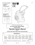
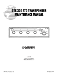
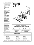
1
2
OPTIONAL ACCESSORIES
INTAKE
HOSE COUPLER KIT 8" (203mm) TR
P/N 810525 Quick release coupler joins 2
hoses together to increase vacuuming
distance and allows hoses to be separated
for storage.
HOSE CONNECTOR KIT 8" (203mm) TR
P/N 810524
HOSE CONNECTOR KIT 10" (254mm) HTR
P/N 810776
For permanently connecting 2 hoses together
to increase vacuuming distance .
EXHAUST
ALL MODELS
EXHAUST EXTENSION KIT P/N 810637
Increases exhaust height 11"(280mm) for
loading debris into elevated locations.
EXHAUST HOSE KIT P/N 811206
[6"(152mm) x 10' (3.0m)] Quick release
coupler and hose increases exhaust distance.
EXHAUST HOSE COUPLER KIT P/N 811207
[6"(152mm)] Quick release coupler joins 2
hoses together to increase vacuuming
distance and allows hoses to be separated for
storage.
EXHAUST HOSE CONNECTOR KIT
P/N 800336 [6"(152mm)] Permanently joins
2 exhaust hoses together to increase
exhaust distance.
PANEL FILTER KIT P/N 810584 Provides air
filter panel for use on truck and trailer
mounted debris enclosures.
PORTABLE DEBRIS BAG P/N 810660
1.3 yds.3 (1.0m3) or 28.4 bushels (1000L).
For portable use. Several bags can be filled
and left for later pickup.
T h a n k Yo u f o r S e l e c t i n g
The Powerful TRUCK LOADER VACUUM
Operator Owner's Manual
HTR1803V, TR1304H, TR1104
Specifications
3
ENGINE:
ENGINE:
ENGINE:
ENGINE:
ENGINE:
H.P.
WEIGHT
TYPE
FUEL CAPACITY
OIL CAPACITY
UNIT TOTAL WEIGHT
TOTAL SHIPING WEIGHT:
UNIT SIZE:
Part No. 811202
HTR1803V
TR1304H
TR1104
18 H.P. TWIN OHV VANGUARD GUARD
79 lbs. (35.83 kg)
Briggs & Stratton 4 Cycle IC Twin
9 qt.(8.52 L),Float feed carb.& fuel pump
1.75 qt. (1.66 L), Oil pump w/filter
13.0 HP (10.68 kW)
68.4 lbs. (31 kg)
HONDA 4 cycle
6.9 qt. (6.0 L)
1.16 qt. (1.1 L)
11.0 HP (9.04 kW)
52.0 lbs. (23.6 kg)
B & S 4 cycle Intek I/C
4.0 qt. (3.8 L)
0.875 qt. (0.8 L)
274 lb (124.3 kg)
302 lb (136.9 kg)
240 lb (108.9 kg)
266 lb (120.7 kg)
224 lb (101.6 kg)
250 lb (113.4 kg)
OVERALL LENGTH: HTR 36.5"(0.93m) / TR 35"(0.89M) OVERALL WIDTH: 24.25" (0.62m)
Page 1 of 12
OVERALL HEIGHT: 66" (1.68m)
Form No. F022404A
IN THE INTEREST OF SAFETY
5
BEFORE STARTING ENGINE, READ AND UNDERSTAND THE “ENTIRE OPERATOR'S MANUAL &
ENGINE MANUAL.”
THIS SYMBOL MEANS WARNING OR CAUTION. DEATH, PERSONAL INJURY AND/OR PROPERTY
DAMAGE MAY OCCUR UNLESS INSTRUCTIONS ARE FOLLOWED CAREFULLY.
WARNING!
The engine exhaust from this product contains chemicals known to the State
of California to cause cancer, birth defects or other reproductive harm.
WARNING: DO NOT
1. DO NOT run engine in an enclosed area.
Exhaust gases contain carbon monoxide, an
odorless and deadly poison.
2. DO NOT place hands or feet near moving
or rotating parts.
3. DO NOT store, spill or use gasoline near
an open flame, or devices such as a stove,
furnace, or water heater which use a pilot
light or devices which can create a spark.
4. DO NOT refuel indoors where area is not
well ventilated. Outdoor refueling is recommended.
5. DO NOT fill fuel tank while engine is
running. Allow engine to cool for 2 minutes
before refueling. Store fuel in approved
safety containers.
6. DO NOT remove fuel tank cap while
engine is running.
7. DO NOT operate engine when smell of
gasoline is present or other explosive
conditions exist.
8. DO NOT operate engine if gasoline is
spilled. Move machine away from the spill
and avoid creating any ignition until the
gasoline has evaporated.
9. DO NOT transport unit with fuel in tank.
10. DO NOT smoke when filling fuel tank.
11. DO NOT choke carburetor to stop
engine. Whenever possible, gradually
reduce engine speed before stopping.
12. DO NOT run engine at excessive
speeds. This may result in injury &
/or damage to unit.
13. DO NOT tamper with governor springs,
governor links or other parts which may
change the governed engine speed.
14. DO NOT tamper with the engine speed
selected by the engine manufacturer.
15. DO NOT check for spark with spark plug
or spark plug wire removed. Use an
approved tester.
16. DO NOT crank engine with spark plug
removed. If engine is flooded, place throttle
in “FAST” position and crank until engine
starts.
17. DO NOT strike flywheel with a hard
object or metal tool as this may cause
flywheel to shatter in operation. Use proper
tools to service engine.
18. DO NOT operate engine without a
muffler. Inspect periodically and replace, if
necessary. If engine is equipped with
muffler deflector, inspect periodically and
replace, if necessary, with correct deflector.
19. DO NOT operate engine with an
accumulation of grass, leaves, dirt or other
combustible material in the muffler area.
20. DO NOT use this engine on any forest
covered, brush covered, or grass covered
unimproved land unless a spark arrester is
installed on the muffler. The arrester must
be maintained in effective working order by
the operator. In the State of California the
above is required by law (Section 4442 of
the California Public Resources Code).
Other states may have similar laws.
Federal laws apply on federal lands.
SOUND
7
TABLE OF CONTENTS
2
SAFETY INSTRUCTIONS
GENERAL SAFETY
3
3
ASSEMBLY
4
PARTS BAG & CONTROLS
4
LABELS
5-7
OPERATION
8-9
MAINTENANCE
PARTS DRAWING & LIST 10 - 12
12
TROUBLESHOOTING
12
WARRANTY
○
○
○
○
○
○
○
○
○
○
○
○
○
○
○
○
○
○
○
Part No. 811202
○
○
○
○
○
○
○
○
○
○
○
○
○
○
NOTE: Sound power level listed is the highest value for any model in this manual.
Please refer to serial plate on the unit for the sound power level for your model.
Sound level of 105 dBA at operator position
GENERAL CONDITION:
TEMPERATURE:
○
○
○
○
○
○
○
○
○
○
○
121 dB
(HTR1803V MODEL)
WIND SPEED:
WIND DIRECTION:
HUMIDITY:
○
○
BAROMETRIC PRESSURE:
○
Page 2 of 12
22. DO NOT run engine without air cleaner
or air cleaner cover.
23. DO NOT operate during excessive
vibration!
24. DO NOT leave machine unattended
while in operation.
25. DO NOT park machine on a steep grade
or slope.
WARNING: DO
1. ALWAYS DO remove the wire from the
spark plug when servicing the engine or
equipment TO PREVENT ACCIDENTAL
STARTING.
2. DO keep cylinder fins and governor
parts free of grass and other debris
which can affect engine speed.
3. DO pull starter cord slowly until resistance is felt. Then pull cord rapidly to avoid
kickback and prevent hand or arm injury.
4. DO examine muffler periodically to be
sure it is functioning effectively. A worn or
leaking muffler should be repaired or
replaced as necessary.
5. DO use fresh gasoline. Stale fuel can
gum carburetor and cause leakage.
6. DO check fuel lines and fittings frequently
for cracks or leaks. Replace if necessary
7. Follow engine manufacturer operating
and maintenance instructions.
8. Inspect machine and work area before
starting unit.
8
Sound tests conducted were in accordance with 2000/14/EEC and
were performed on 05/28/2002 under the conditions listed:
6
21. DO NOT touch hot muffler, cylinder, or
fins because contact may cause burns.
Sunny
45° F (7.2° C)
5 MPH (8.1 kmh)
South West
60 %
30.18" Hg (767mm Hg)
VIBRATION
VIBRATION LEVEL 0.02g
Vibration levels at the operators handles were
measured in the vertical, lateral, and longitudinal
directions using calibrated vibration test equipment.
Tests were performed on 07/14/94 under the
conditions listed:
GENERAL CONDITION:
TEMPERATURE:
WIND SPEED:
WIND DIRECTION:
HUMIDITY:
BAROMETRIC
PRESSURE:
Sunny
78° F (23.8° C)
16 MPH (25.7 kmh)
South East
62 %
30.10" Hg (765mm Hg)
Form No. F022404A
GENERAL SAFETY
9
For your safety and the safety of others, these directions should be followed:
Do not operate this machine without first reading
owner's manual and engine manufacturer's manual.
Use of Ear Protection is recommended while
operating this machine.
Use of Eye and Breathing protection is recommended when using this machine, especially in dry
and dusty conditions. Optional bag cover directs dust
toward ground, away from the operator.
·DO NOT place hands or feet inside nozzle intake opening,
near debris outlet or near any moving parts.
·DO NOT start engine without hose and exhaust elbow
connected firmly in place to housing and exhaust outlet.
10
ASSEMBLY
Read all safety and operating instructions
before assembling or starting this unit.
PUT OIL IN ENGINE BEFORE STARTING.
Your Billy Goat is shipped from the factory in one carton and is
completely assembled except for the exhaust elbow, nozzle, handle
loop for nozzle, hose booms, hose bands, hose coupler, hose clamps
and related hardware.
1. ASSEMBLE exhaust elbow (item 10), to main unit and firmly tighten
knobs (item 90), that are preassembled to main unit.
2. SECURELY ATTACH unit to tailgate of a truck or to a trailer, so that
the exhaust discharges into an enclosed container.
3. ATTACH hose to hose coupler (item 24), using hose clamp (item
60) NOTE: This unit is equipped with a unidirectional hose. Assemble
hose so that interior hose material seams face toward unit.
4. ASSEMBLE hose coupler to housing of main unit and securely
tighten knob (item 13), that is preassembled to housing front plate.
11
·DO NOT operate without discharging exhaust into enclosed
container.
·DO NOT operate during excessive vibration.
·DO NOT remove hose until engine has been turned off and has
come to a complete stop.
·DO NOT operate machine with hose or exhaust elbow removed.
·DO NOT use this machine for vacuuming exclusively sand,
dust, fine dirt, rock, glass, string like material, grain, rags,
cans, metal, bark or water.
·DO NOT operate this machine on slopes greater than 20%.
·DO NOT pick up any hot or burning debris, or any toxic or
explosive material.
·DO NOT allow children to operate this equipment.
5. ASSEMBLE nozzle handle loop (item 82), to nozzle handle using
screw (item 80), washer (item 6) and lock nut (item 5). Adjust handle
loop to desired height and angle and securely tighten in place.
6. ASSEMBLE nozzle handle (item 78), to nozzle (item 77), using
screws (item 80), washers (item 79), washers (item 4) and lock nuts
(item 5).
7. ATTACH assembled nozzle to hose using hose clamp (item 60).
Before tightening hose clamp, position nozzle handle upward when hose
is stretched to prevent twisting load on hose assembly during operation.
8. ASSEMBLE tube square boom (item 51), to boom pivot (item 50),
using chain loop assembly (item 54), washers (item 4) and lock nut
(item 52).
9. ASSEMBLE remaining chain loop assembly (item 54), to end of tube
square boom (item 51) using washer (item 4) and lock nut (item 52).
10. SLIDE boom assembly into square tube on front of housing.
11. ASSEMBLE hose bands (item 56) around hose and onto chain loop
assemblies on boom assembly using screws (item 55) and lock nuts
(item 52) (see ADJUSTING HOSE BOOM on page 5).
PACKING CHECKLIST
TR MODELS
Briggs & Stratton 11 HP
Honda 13 HP
Engine
Manual Per
Model
Boxing Checklist
These items should be included in
your carton. If any of these parts are
missing, contact your dealer.
Check
Exhaust Elbow 811191
10
HTR MODELS
51
Briggs & Stratton
Vanguard-Twin 18 HP
50
Boom Square Arm 810875
Boom Pivot WA 810870
Per Model
Band Hose Boom 8" (203mm) TR
810880 Qty. 2
Per Model
Hose 8"x 12.5' TR
P/N 810523
56
Per Model
Hose 10"x 12.5' HTR
P/N 810705
59
Handle Loop Nozzle
P/N 811019
Coupler Weld Assy. 8"(203mm)
TR 811170
Coupler Weld Assy. 10" (254mm)
HTR 811179
Per Model
60
Parts Bag &
Literature Assy
P/N 811128
78
Hose Clamps 8"(203mm) TR
810566 Qty. 2
Hose Clamps 10" (254mm) HTR
810706 Qty. 2
Handle Nozzle 811020
TR and HTR
Per Model
Parts Bag
& Literature
Assy
Part No. 811202
Band Hose Boom 10" (254mm) HTR
810868 Qty. 2
77
Nozzle 8"(203mm) TR 811007
Nozzle 10" (254mm) HTR 811005
Page 3 of 12
Form No. F022404A
13 CONTROLS
PARTS BAG & LITERATURE ASSY P/N 811201
12
Throttle Controls
79
Washer 5/16
Fender
8172020 Qty. 4
Literature Checklist
Check
Owner's
Manual
Honda
Units have
frame
mounted
throttle
controls as
shown
here.
Owner's
Manual
811202
Washer 5/16 SAE
8172008 Qty. 4
54 Chain Loop Assy
Nut Lock 1/4-20
52 8160001 Qty. 4
Nut Lock 5/16-18
8160002 Qty. 3
6
Washer 5/16 FLAT CUT
8171003 Qty. 1
Literature
Parts Bag
811203
STOP
810878 Qty. 2
Check
Literature
HTR / TR
Accessories
Check
Warranty
Card
Stop
position
Literature
HTR / TR
Accessories
811208
Briggs Vanguard Units
have an engine mounted
throttle control.
Engine
Stop
Switch
Warranty
Card
400972
Start
position
Screw Cap 5/16-18 x 1 1/2
80 8041030 Qty. 3
EU Declaration
of Conformity
& EU
Distributor List
55 Screw Cap 1/4-20 x 1 3/
Check
FAST
5
Check
Literature
Parts Bag
EU Declaration
of Conformity &
EU Distributor
List 811204
Stop
position
4 8041009 Qty. 2
14
START
SLOW
4
Start
position
INSTRUCTION LABELS
15
These labels should be included on your Vacuum. If any of these
labels are damaged, replace them before putting this equipment into
operation. Item and part numbers are given to help in ordering
replacement labels..
ENGINE LABELS
Briggs & Stratton Vanguard
FUEL SHUTOFF
ON
RUN
STOP
RUN
CHOKE
DANGER
OFF
ENGINE MAINTENANCE
810736
1. CHECK OIL LEVEL
8 HOURS
2. CHECK & CLEAN AIR CLEANER
25 HOURS
3. CHANGE OIL
50 HOURS
4. REPLACE OIL FILTER
100 HOURS
5. CLEAN COOLING FINS
100 HOURS
See Operating and Maintenance Instructions
Label Danger Keep Hands
Label Danger Flying Material
and Feet Away
Item No. 19 Part No. 810736
Item 3 Part No.400424
Label Read Owner's Manual
Item 15 Part No.830301
Honda
OIL ALERT
WHEN OIL LEVEL LOW,
ENGINE STOPS IMMEDIATELY.
Label Ear Eye Breathing
Item No. 48 Part No. 890254
400268
WARNING
EXPLOSIVE FUEL
STOP ENGINE AND ALLOW T O
COOL BEFORE REFUELING.
Label Do Not Fill While Engine Is Hot
Item 81 Part No.400268
USE PROTECTION
BEFORE OPERATING, MAKE SURE:
EXHAUST ELBOW IS ATTACHED.
EXHAUST IS DISCHARGING INTO
ENCLOSED CONTAINER.
HOSE IS ATTACHED.
ALL GUARDS ARE ATTACHED.
OPERATING INSTRUCTION IS OBTAINED.
830138
890254
READ OWNER'S MANUAL
H O N DA
INSPECT MACHINE BEFORE EACH USE AND REPLACE ANY
WORN AND DAMAGED PARTS.
PROPERLY SECURE EQUIPMENT BEFORE TRANSPORTING.
NEVER SERVICE UNIT WITHOUT DISCONNECTING SPARK PLUG WIRE.
USE ONLY A QUALIFIED MECHANIC TO SER VICE THIS MACHINE.
A D E I N J A PA N
ON
Label Caution
Item 47 Part No.830138
OFF
RUN
Part No. 811202
O T O R C O ., L T D . M
Briggs & Stratton
ABRASIVE DEBRIS WILL SHORTEN UNIT LIFE.
Clean debris from all engine surfaces
regularly to prevent engine overheating,
premature failure, or fire.
M
STOP ENGINE AND ALLOW T O
COOL BEFORE REFUELING.
KEEP ENGINE CLEAN OF DEBRIS.
CHOKE
THIS ENGINE EQUIPPED WITH
LOW OIL SENSOR, IF ENGINE WILL
NOT START, CHECK OIL LEVEL
Label Warning Engine Overheat
Item 49 Part No.811215
Page 4 of 12
Read and follow Operating
Instructions before running engine.
Gasoline is flammable. Allow engine
to cool at least 2 minutes before fueling.
Engines emit carbon monoxide,
DO NOT run in enclosed area.
Form No. F022404A
OPERATION
16
INTENDED USE: This machine is designed for vacuuming
leaves, grass clippings and other types of organic litter.
Debris mixed with cans, bottles and small amounts of sand can
be vacuumed; however, it is not this machine's primary
purpose. Vacuuming cans, bottles and sand will affect the
longevity of your machine.
Do not operate if excessive vibration occurs. If excessive
vibration occurs, shut engine off immediately and check for
damaged or worn impeller, loose impeller bolt, loose impeller
key, loose engine or lodged foreign objects. Note: See parts list
for proper impeller bolt torque specifications. (See trouble
shooting section on page 12).
Like all mechanical tools, reasonable care must
be used when operating machine.
16.6
HOSE OPERATION TIPS
THE HOSE IS A REPLACEABLE WEAR ITEM.
FOR BEST HOSE OPERATION RESULTS, FOLLOW THESE
RECOMMENDATIONS.
Keep hose as straight as possible during operation for best
pick-up and to avoid clogs.
Avoid sharp bends in hose which will reduce efficiency and may
promote clogs.
NEVER DRAG HOSE. Always remove and store hose before
transporting unit.
Inspect machine work area and machine before operating.
Make sure that all operators of this equipment are trained
in general machine use and safety.
PUT OIL IN ENGINE BEFORE STARTING.
16.1
STARTING
SECURE LOADER TO TAILGATE OR MOUNTING:
ENGINE: See engine manufacturer’s instructions
for type and amount of oil and gasoline used. Engine must be
level when checking and filling oil and gasoline.
ENGINE SPEED: Controlled by throttle lever on the frame
(18HP Twin on engine). Under normal conditions, operate at
minimum throttle to accomplish your current cleaning task.
FUEL VALVE: Move fuel valve to "ON" position (when provided
on engine).
fig. 1
INTAKE HOSE: Must be attached to front plate to start engine.
CHOKE: Located on engine near engine throttle panel.
ADJUSTING HOSE BOOM:
STOP SWITCH: Move to on position (when provided).
THROTTLE: Move remote throttle control to fast position. Pull
starting rope to start engine.
IF YOUR UNIT FAILS TO START:
See Troubleshooting on page 12.
16.2
Properly adjusting the boom will prevent most hose clogs from
occurring and will give optimum vacuum performance by
keeping hose straight next to housing (see fig. 2).
Boom Assembly
after hose has
been stretched.
VACUUMING OPERATION
EXHAUST FLAPPER: Discharging into enclosed container,
position exhaust flapper to desired opening and secure
adjustment knob before starting engine. NOTE: An enclosed
container must capture all debris delivered into it preventing
any debris from blowing back onto unit's engine (see page 1
optional accessories).
NOZZLE: With machine running and fully assembled, move
nozzle in sweeping motions over debris. For maximum pickup,
move nozzle close to debris, but without blocking air flow into
the nozzle (see figure 1). NOTE: Never bury nozzle into debris.
Part No. 811202
Page 5 of 12
Hose
fig. 2
Hose Bands.
Stretch hose
out before
clamping.
Form No. F022404A
16
16.6
OPERATION
continued
HOSE OPERATION TIPS continued
UNCLOGGING A CLOGGED HOSE:
With engine running and unit secured to tailgate, fully stretch
hose in a straight line to dislodge the clog.
If the clog will not clear, turn unit off, and allow engine to come
to a complete stop. Remove hose and manually clear hose
clog.
UNCLOGGING A CLOGGED HOUSING OR
EXHAUST ELBOW:
Turn engine off and wait for impeller to come to a
complete stop. Disconnect spark plug wire.
Danger, the clog may contain sharp materials.
Wearing durable gloves, clear the clog.
Reconnect spark plug wire.
HOSE LIFE:
To increase hose life, periodically rotate hose and reposition
nozzle and coupler on front plate of unit. This increases hose
life by keeping hose from wearing only on one side.
HEAVY DEBRIS REMOVAL
TILT NOZZLE FORWARD TO PICK UP DIFFICULT DEBRIS.
Part No. 811202
Page 6 of 12
Form No. F022404A
16
16.4
OPERATION
continued
HANDLING & TRANSPORTING:
ALWAYS REMOVE LOADER FROM TAILGATE OR MOUNTING BEFORE TRANSPORTING OR OPENING TAILGATE.
Using two people to lift machine is recommended. Lift holding
the rear handle and front of frame. Secure in place during
transport.
HOSE: DO NOT drag the hose with vehicle.
16.5
STORAGE
Turn fuel supply off when unit is not in use.
Never store engine indoors or in enclosed poorly ventilated
areas with fuel in tank, where fuel fumes may reach an open
flame, spark or pilot light, as on a furnace, water heater,
clothes dryer or other gas appliance.
If engine is to be unused for 30 days or more, prepare as
follows:
Be sure engine is cool. Do not smoke. Remove all
gasoline from carburetor and fuel tank to prevent gum deposits
from forming on these parts and causing possible malfunction
of engine. Drain fuel outdoors, into an approved container, away
from open flame. Run engine until fuel tank is empty and
engine runs out of gasoline.
NOTE: Fuel stabilizer (such as Sta-Bil) is an acceptable
alternative in minimizing the formation of fuel gum deposits
during storage. Add stabilizer to gasoline in fuel tank or storage
container. Always follow mix ratio found on stabilizer container.
Run engine at least 10 min. after adding stabilizer to allow it to
reach the carburetor.
HOSE STORAGE: Storing hose in a covered area, out of
sunlight and heat will prolong hose life. Do not store hose
where it could be stepped on or where other objects could crush
or damage hose.
Page 7 of 12
Part No. 811202
Form No. F022404A
MAINTENANCE
17
Use only a qualified mechanic for
any adjustments, disassembly or any
kind of repair .
WARNING: TO AVOID PERSONAL INJURY, ALWAYS
TURN MACHINE OFF, MAKE SURE ALL MOVING
PARTS COME TO A COMPLETE STOP.
DISCONNECT SPARK PLUG WIRE
BEFORE SERVICING UNIT.
ENGINE: See engine manufacturer
operator's instructions.
RECONNECT SPARK PLUG WIRE,
GUARDS AND HOSE BEFORE STARTING ENGINE.
Remove and Service foam air cleaner and inner air filter every 25
hours of use or every 10 hours or less for extremely dusty conditions (see engine manual).
Keep engine and engine cooling fins clean from dust and debris
build-up.
Replace any worn or damaged parts as required.
DO NOT operate if excessive vibration occurs. If excessive vibration
occurs, shut engine off immediately. Remove spark plug wire and
check for damaged impeller, loose impeller bolt, loose impeller key
or lodged foreign objects. Refer to parts list (item 16) on page 11 for
proper torque specifications.
17.1
IMPELLER REMOVAL
1. Wait for engine to cool and disconnect spark plug.
2. Disconnect hose from unit.
3. Remove boom assembly.
4. Remove cable assy. interlock (item 43), from front plate of
assembly (item 41).
5. Remove front plate assembly (item 41).
6. Remove impeller bolt (item 16) and lock washer (item 17).
7. Pull the impeller outward. If impeller slides freely, proceed to (steps
10 to 14 for TR units or to step 14 for HTR units). If not, complete
steps 8 thru 9 as required.
8 . Place two crowbars between impeller and housing on opposite
sides. Pry impeller away from engine until it loosens. Using a
penetrating oil can help loosen a stuck impeller.
9. If the impeller does not loosen, obtain a 1” (25.4mm) longer bolt
of the same diameter and thread type as the impeller bolt. Thread
longer bolt by hand into the crankshaft until bolt bottoms. Using a
suitable gear or wheel puller against the bolt head and the impeller
back-plate (near the blades), remove impeller from shaft.
10. [TR ONLY] Remove engine base mounting bolts, and nuts.
11. [TR ONLY] Access engine bolts on inside of housing that
connect engine face to the fan housing. Bend ends of lock clip away
from bolt heads and remove bolts.
12. [TR ONLY] Slide engine shaft out of impeller.
13. [TR ONLY] When impeller is free of the engine shaft, align
impeller with opening, and diagonally lift impeller out of housing.
14. Using a new impeller bolt and lockwasher (and engine bolt lock
clip, TR only), reinstall (engine for TR only) and new impeller in
reverse order.
15. Tighten impeller bolt. Torque HTR1803V and TR1304H impeller bolt
to [ 50 Ft. Lbs. (68 N.m)] and TR1104 to [ 60 Ft. Lbs. (81.4 N.m)] (see
item 16 on page 11).
16. Reinstall spark plug wire.
ENGINE
When servicing engine refer to specific manufacturers engine
owner's manual. All engine warranty is covered by the specific
engine manufacturer. If your engine requires warranty or other
repair work contact your local servicing engine dealer. When
contacting a dealer for service it is a good idea to have your
engine model number available for reference(See table page 11).
If you can not locate a servicing dealer in your area you can
contact the manufacturers national service organization.
To reach:
Briggs & Stratton: 800-233-3723
American Honda: 800-426-7701
Page 8 of 12
Part No. 811202
Form No. F022404A
MAINTENANCE
17
17.2
Follow these hourly
maintenance intervals.
Maintenance Schedule
Maintenance Operation
continued
Every
Use
Every 5 hrs Every 10
or (Daily)
hrs
Every 25
hrs
Engine (See Engine Manual)
Check for excessive vibration
17.3
INTERLOCK SYSTEM
With hose coupler installed (as shown in Fig. 4) the switch is open
& engine is not grounded out, allowing engine to run.
HTR1803V SYSTEM
Clean Hose
Keep engine free of debris
Spark Plug
Inspect for loose parts
INTERLOCK
SWITCH
Item 43
Inspect for worn or damaged parts
A
Grease (see page 10)
ENGINE
SWITCH
Spark Plug
TR1304H SYSTEM
OIL
ALERT
MAINTENANCE HISTORY
Date of Service
IGNITION
SWITCH
Service Performed
SPARK
PLUG
INTERLOCK
SWITCH
ITEM 43
OIL LEVEL
PLUG
TR1104 SYSTEM
THROTTLE
STOP
SPARK
PLUG
ENGINE
SWITCH
INTERLOCK
SWITCH
ITEM 43
Fig. 3
43
Fig. 4
Part No. 811202
Page 9 of 12
Form No. F022404A
A
18
SEE PAGE 9
MAINTENANCE
PARTS DRAWING
HTR1803V, TR1304H,
TR1104
Part No. 811202
Page 10 of 12
Form No. F022404A
19
Parts List
ITEM
1
2
3
4
5
6
7
8
9
10
11
12
13
14
15
16
17
18
19
20
21
22
23
24
25
26
27
28
29
30
31
32
33
34
35
36
37
38
39
40
41
42
43
44
45
46
47
48
49
50
51
52
53
54
55
56
57
58
59
60
61
62
63
Part No. 811202
* Denotes standard
hardware item that may
be purchased locally.
Denotes parts found in
parts bag assembly.
FLA PPER 10" INTA KE W/LA BEL
FLA PPER 8" INTA KE W/ LA BEL
NUT LOCK 10-24
LA BEL DA NGER KEEP HA NDS A ND FEET A WA Y
WA SHER 5/16 SA E (11/32 ID x 11/16 OD x 1/16)
NUT LOCK 5/16-18
WA SHER 5/16 FLA T CUT (3/8 I.D. x 7/8 O.D. x 1/16)
PLUG 3/4"
DEFLECTOR EXHA UST 7"
CA RRIA GE BOLT 5/16-18 x 3 1/2
ELBOW A SSY TR/HTR
HTR1803V
PA RT NO.
811183
- - 400424
*8172008
*8160002
*8171003
811123
811111
*8024050
811191
TUBE CLA MP
KNOB
IMPELLER A SSY (INCLUDES 16(1),17(1),18(1), 20(1))
LA BEL REA D OWNER'S MA NUA L
SCREW CA P 3/8-24 x 2" GR 8 [50 Ft. Lbs. (68 N.m)]
SCREW CA P 3/8 - 24 X 2 1/4 GR 8 [50 Ft. Lbs. (68 N.m)]
SCREW CA P 7/16 - 20 X 2 GR 5 [60 Ft. Lbs. (81.4 N.m)]
WA SHER LOCK 3/8 TWISTED TOOTH
WA SHER LOCK 7/16 TWISTED TOOTH
KEY SQ. 1/4 x 2 3/4
KEY SQ. 1/4 X 2 1/4
LA BEL DA NGER FLY ING MA TERIA L
SPA CER IMPELLER
GUA RD MA NIFOLD
GUIDE STA RTER ROPE (HA LF)
TUBE REA R FRA ME
COUPLER HOSE W/GRIP
PA D FRA ME SHORT
CA RRIA GE BOLT 5/16-18 x 2 1/4
CA RRIA GE BOLT 5/16-18 x 4 1/2
SCREW CA P 5/16-18 x 1 1/2
SCREW CA P 5/16-18 x 2 1/2
ENGINE 18 H.P. V N W\CONTROL PA NEL
ENGINE HONDA 13HP
ENGINE BRIGGS 11 HP INTEK I/C
KNOB
NUT LOCK W.A .
WA SHER 3/4, PLA STIC
STUD 3/4 -10 x 5 1/2
SCREW MA CHINE #10-24 x 2
PIN COTTER 1/8 x 1"
WA SHER 3/8 SA E
NUT LOCK 3/8-16
SCREW SHEET META L 1/4 A B x 3/4
GUA RD MUFFLER
BA SE ENGINE
PA D FRA ME LONG
PLA TE FRONT 10" HTR W/INTERLOCK (INCL. 1,2,3,5(2),7,13,43,44,49,59,83,84
PLA TE FRONT 8" TR W/INTERLOCK (INCL. 1,2,3,5(2),7,13,43,44,49,59,83,84,87
PLUG CA P 1" SQUA RE
CA BLE A SSY SWITCH SV
CLIP-CA BLE LIFT
WA SHER-1.5 OD X 0.531 ID
SPRING
LA BEL CA UTION
LA BEL EA R,EY E,BREA THING
LA BEL WA RNING ENGINE OV ERHEA T
BOOM-PIV OT W.A .
TUBE-SQUA RE BOOM A RM
NUT LOCK 1/4-20
HOSE 10" x 12.5' HTR
HOSE 8" x 12.5' TR
CHA IN-LOOP A SSY
SCREW CA P 1/4-20 x 1 3/4
BA ND HOSE BOOM 10" HTR
BA ND HOSE BOOM 8" TR
HOUSING A SSY W/LA BELS (INCLUDES 5(2), 13(2), 45(2), 46(2), 47, 48)
NOZZLE A SSY 10" HTR (INCL. 4(2), 5(3), 6, 23, 77, 79(4), 80(2), 82, 83, 84
NOZZLE A SSY 8" TR (INCL. 4(2), 5(3), 6, 23, 77, 79(4), 80(2), 82, 83, 84
DESCRIPTION
SPA CER ENGINE INTEK
CLA MP HOSE 10" HTR
CLA MP HOSE 8" TR
ELBOW EXHA UST WA
PA D FRA ME CLA MP TUBE
SUPPORT PLA TE ENGINE / SPA CER ENG.
Page 11 of 12
1
-2
13
22
47
1
1
1
1
TR1304H
PA RT NO.
- - 811174
8164005
400424
*8172008
*8160002
*8171003
811123
811111
*8024050
811191
810953
400339
810930
890301
810962
- - - - 400502
- - *9201125
-- 810736
830112
811059
830533
811218
811179
811120
*8024045
- - *8041030
- - 811224
- - - - 850154
800227
800109
810954
*8059143
*8197031
*8172009
*8160003
*8122082
811058
810907
811122
811182
- - 810535
890442
850200
610308-P
400332
830138
890254
811215
810870
810875
*8160001
810705
- - 810878
*8041009
810868
- - 810912
811010
- - -
1
2
1
1
1
--1
- 1
- 2
1
1
2
1
1
2
1
- 4
- 1
- - 2
2
2
2
2
2
4
18
3
1
1
2
1
2
1
3
2
2
1
1
2
1
1
5
1
2
2
2
1
1
-
- - 810706
- - 811192
811121
810927
2
1
1
1
QTY
-1
2
2
11
20
47
1
1
1
1
TR1104
PA RT NO.
- - 811174
8164005
400424
*8172008
*8160002
*8171003
811123
811111
*8024050
811191
810953
400339
810974
890301
- - 810932
- - 400502
- - *9201125
- - 810736
830112
- - 830533
811218
811170
811120
- - *8024054
*8041030
- - - - 430366
- - 850154
800227
800109
810954
*8059143
*8197031
*8172009
*8160003
- - - - 810907
811122
- - 811173
810535
890442
850200
610308-P
400332
830138
890254
811215
810870
810875
*8160001
- - 810523
810878
*8041009
- - 810880
810976
- - 811009
1
2
1
1
-1
- 1
- 1
-2
1
- 2
1
1
2
- 1
4
- - 1
- 2
2
2
2
2
2
4
18
1
2
1
2
1
3
2
2
1
1
2
1
1
5
1
2
2
2
1
1
810953
400339
810629
890301
- - - - 500188
- - 850132
- - *9201123
810736
830112
- - 830533
811218
811170
811120
- - *8024054
- - *8041034
- - - - 811205
850154
800227
800109
810954
*8059143
*8197031
*8172009
*8160003
- - - - 810907
811122
- - 811173
810535
890442
850200
610308-P
400332
830138
890254
811215
810870
810875
*8160001
- - 810523
810878
*8041009
- - 810880
810976
- - 811009
1
2
1
1
-- 1
- 1
- 1
2
1
- 2
1
1
2
- 1
- 4
- - 1
2
2
2
2
2
2
4
18
- - 1
2
1
2
1
3
2
2
1
1
2
1
1
5
1
2
2
2
1
1
- - - - 810566
811192
811121
810965
2
1
1
1
430355
- - 810566
811192
811121
810965
1
2
1
1
1
QTY
QTY
-1
2
2
11
20
47
1
1
1
1
Form No. F022404A
19
* Denotes standard
hardware item that may
be purchased locally.
Parts List
continued from
page 11.
ITEM
64
65
66
67
68
69
70
71
72
73
74
75
76
77
78
79
80
81
82
83
84
85
86
87
88
89
90
H TR 1 8 0 3 V
PA R T N O .
*8 1 7 7 0 1 2
- - *8 0 4 1 0 5 0
- - *8 0 4 1 0 5 0
*8 0 4 1 0 0 8
*8 0 4 1 0 5 3
810917
*8 0 4 1 0 2 8
810916
811097
*8 1 7 1 0 0 2
810904-1
- - 8161041
811005
811020
*8 1 7 2 0 2 0
*8 0 4 1 0 3 0
400268
811019
500267
890132
811100
811101
500282
890440
811139
811230
D ES C RIPTIO N
W A S H ER L O C K 3 /8
W A S H ER L O C K 5 /1 6 EX T. TO O TH
S C R EW C A P 3 /8 - 1 6 X 1
S C R EW C A P 3 /8 - 1 6 X 1 1 /2 Z P
S C R EW C A P 3 /8 - 1 6 x 1 "
S C R EW C A P 1 /4 - 2 0 X 1 1 /2
S C R EW C A P 3 /8 - 1 6 X 1 3 /4 Z P
A N G L E B R K T R .H .
S C R EW C A P 5 /1 6 - 1 8 x 1 "
A N G L E B R K T L .H .
S PA CER
W A S H ER FL A T C U T 1 /4
C O NTR O L THR O TTL E A S S Y
S C R EW M A C H IN E 1 0 - 2 4 x 1 - 1 /2 "
N U T L O C K 5 /1 6 - 1 8 TH IN HT.
N O Z Z L E FO RM ED S TEEL 1 0 "
N O Z Z L E FO RM ED S TEEL 8 "
H A ND L E N O Z Z L E W / G R IP
W A S H ER FEN D ER 5 /1 6
S C R EW C A P 5 /1 6 - 1 8 X 1 1 /2
L A B EL D O N O T FIL L W H EN EN G IN E IS H O T
H A ND L E L O O P N O Z Z L E
G R IP H A N D L E
PL U G C A P
FR A ME S ID E R IG H T W A TR /H TR
FR A ME S ID E L EFT W A TR /H TR
S TR A IN R EL IEF
PL U N G ER S W ITC H
TU B E H A N D L E L IFT
K N O B 3 /8 " S O L ID H U B
TROUBLESHOOTING
20
Problem
2
2
- 12
1
4
1
2
1
1
1
1
- 2
1
1
4
3
1
1
4
4
1
1
1
1
2
2
TR 1 3 0 4 H
PA R T N O .
*8 1 7 7 0 1 2
- - - - 8041052
*8 0 4 1 0 5 0
*8 0 4 1 0 0 8
*8 0 4 1 0 5 3
811096
*8 0 4 1 0 2 8
810969
811098
*8 1 7 1 0 0 2
811222
8059141
8161041
- - 811007
811020
*8 1 7 2 0 2 0
*8 0 4 1 0 3 0
400268
811019
500267
890132
811100
811101
500282
890440
811139
811230
Q TY
2
- 2
12
1
4
1
2
1
1
1
1
2
2
- 1
1
4
3
1
1
4
4
1
1
1
1
2
2
TR 1 1 0 4
PA R T N O .
- - *8 1 8 1 0 0 8
- - 8041052
*8 0 4 1 0 5 0
*8 0 4 1 0 0 8
*8 0 4 1 0 5 3
811096
*8 0 4 1 0 2 8
810969
811098
*8 1 7 1 0 0 2
811222
8059141
8161041
- - 811007
811020
*8 1 7 2 0 2 0
*8 0 4 1 0 3 0
400268
811019
500267
890132
811100
811101
500282
890440
811139
811230
Q TY
2
- 2
12
1
4
1
2
1
1
1
1
2
2
- 1
1
4
3
1
1
4
4
1
1
1
1
2
2
Before Requesting Service Review These Suggestions
Possible Cause
Will not vacuum or has poor
vacuum performance.
Q TY
Solution
Nozzle height too high or too low. Clogged hose or exhaust.
Excessive quantity of debris.
Adjust nozzle position. Unclog hose or exhaust (see page 6).
Allow air to feed with debris.
Abnormal vibration.
Loose or out of balance impeller or loose engine.
Check impeller and replace if required. Check Engine.
Engine will not start.
Throttle & / or stop switch in off position. Out of gasoline. Bad or
old gasoline. Spark Plug wire disconnected. Dirty air cleaner.
Hose not installed, allowing interlock wire to ground.
Check stop switches, throttle, and gasoline. Connect spark plug wire.
Clean or replace air cleaner. Or contact a qualified service person.
Install hose onto housing.
Engine is locked, will not
pull over.
Debris locked inside impeller. Engine problem.
See page 6, Clearing a clogged impeller housing. Contact an engine
servicing dealer for engine problems.
22.1
21
Engine Service and Warranty
Contact your nearest engine manufacturer's authorized
servicing dealer.
22
Record your machine model, serial number and
date-of-purchase and where purchased
Serial Plate
1803 S. Jefferson
P.O. Box 308
Lee's Summit,
MO 64063 / USA
Tel (816) 524-9666
Fax (816) 524-6983
R
Model
Serial No.
121 dB
(HTR1803V
MODEL)
Unit(Weight)
lbs.
Engine Power
kg
kW
rpm
min-1
WARRANTY PROCEDURE
Should a Billy Goat Machine fail due to a defect in material and/or
workmanship, the owner should make a warranty claim as follows:
-The Machine must be taken to the dealer from whom it was purchased
or to an authorized Servicing Billy Goat Dealer.
-The owner must present the remaining half of the Warranty Registration Card, or, if this is not available, the invoice or receipt.
-The Warranty Claim will be completed by the authorized Billy Goat
Dealer and submitted to their respective Billy Goat Distributor for their
territory. Attention: Service Manager. Any parts replaced under warranty
must be tagged and retained for 90 days.
-The distributor service manager will sign off on the claim and submit it
to Billy Goat for consideration.
-The Technical Service Department at Billy Goat will study the claim and
may request parts to be returned for examination. Billy Goat will notify
their conclusions to the distributor service manager from whom the
claim was received.
-The decision by the Quality / Service department at Billy Goat to
approve or reject a Warranty claim is final and binding.
Note: To process a Warranty Claim, it is necessary to quote the Model & Serial
Number which are printed on the Billy Goat Serial Plate (See owner’s manual).
Purchase
Date
Part No. 811202
BILLY GOAT INDUSTRIES INC.
1803 S.W. JEFFERSON STREET / LEE'S SUMMIT, MO 64082-2312 / USA
PHONE: 816-524-9666 FAX: 816-524-6983
www.billygoat.com
Purchased
from
Page 12 of 12
Form No. F022404A