1
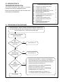
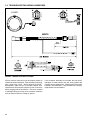
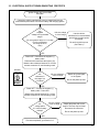
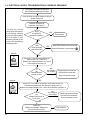
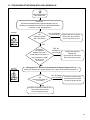
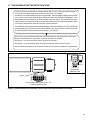
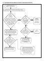
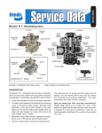
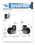
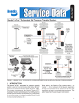
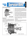
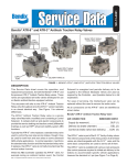
SD-61-4933
Bendix™ BlindSpotter® Side Object Detection System
DESCRIPTION
The Bendix™ BlindSpotter ® side object detection system is
an aid to help professional drivers with vehicle blind-spots,
by alerting them to large metallic objects within the range of
the radar sensor(s) mounted on the side(s) of the vehicle.
Sensor
10 ft.
(3 m.)
Approximate 15 ft. (5 m.)
Detection Zone
Operator
display
Unit
(ODU)
Radar sensor
FIGURE 1 - Bendix™ BlindSpotter® Radar sensor
and in-cab Operator Display Unit (ODU)
Examples of Sensor Locations
Used in conjunction with rear view mirrors and other
instrumentation to maintain safe operation of the vehicle,
the radar sensor(s) provide an approximate ten foot by
fifteen foot detection zone. See Figure 2.
The Bendix BlindSpotter side object detection system can
be installed on one or both sides of the vehicle. The system
is comprised of up to four radar sensor(s) — located on one
side of a vehicle along with a driver display unit, located
on the windshield pillar on that side — to warn the driver
when an object is detected.
FIGURE 2 - Bendix™ BlindSpotter® Radar sensor
detection zone and example locations
Key Section Index
1.0
Operation Section . . . . . . . . . . . . . . . . .4
1.5 What To Expect When Using The Bendix™
BlindSpotter® System . . . . . . . . . . . . . 6
1.6 Alerts And Warnings . . . . . . . . . . . . . .7
1.11Radar Clearance . . . . . . . . . . . . . . . .7
2.0Maintenance Section . . . . . . . . . . . . . . . 8
3.0
Troubleshooting Section . . . . . . . . . . . . .9
3.1 Troubleshooting Overview . . . . . . . . . . 9
1
Warning
The driver is always responsible for the control and
safe operation of the vehicle at all times. The Bendix™
BlindSpotter® Radar system does not replace the
need for a skilled, alert professional driver, reacting
appropriately and in a timely manner, and using safe
driving practices.
Warning
Any audible and/or visual alert by the system means
that a vehicle has been detected by the Bendix
BlindSpotter system and the driver must immediately
act to potentially avoid, or lessen the severity of, a
collision.
Improper use of the Bendix BlindSpotter system
could lead to a serious accident. Read this entire
Service Data Sheet before operating the Bendix
BlindSpotter system. Pay particular attention to the
safety messages below. This guide should be used
in conjunction with proper training.
Limitations of Collision Warning Systems
The Bendix BlindSpotter side collision warning
system is intended solely as an aid for an alert and
conscientious professional driver. It is not to be used
or relied upon to operate a vehicle. The system should
be used in conjunction with rear view mirrors and other
instrumentation to maintain safe operation of the vehicle,
ground personnel, and adjacent property. A vehicle
equipped with the Bendix BlindSpotter system should
be operated in the same safe manner as if the system
were not installed. The system is not a substitute for
normal safe driving procedures. It will not compensate
for any driver impairment, such as drugs, alcohol, or
fatigue. Should the system become inoperative, it could
jeopardize the safety or lives of those who depend on
the system for safety.
Warning
The system will not sense objects if the sensor view is
obstructed. Therefore, do not place objects in front of
the system sensor. Remove heavy buildups of mud, dirt,
ice, and other materials.
Proper installation and placement is critical to correct
operation of the system.
Testing and inspection of the system in accordance with
these instructions and record of the results should be
listed on the daily maintenance report. The units on
operating vehicles must be tested each day (see the
“Testing System Operation” section) prior to the vehicle’s
operation. Results of this test must be recorded in the
maintenance log. People operating this equipment MUST
2
check for proper operation at the beginning of every shift
or safety inspection period.
People’s lives depend on the proper installation of this
product in conformance with these instructions. It is
necessary to read, understand, and follow all instructions
shipped with the product.
Failure to follow all safety precautions and instructions
may result in property damage, serious injury, or death.
The Bendix BlindSpotter system is intended for commercial
use. Proper installation of this system requires a good
understanding of truck electrical systems and procedures,
along with proficiency in the installation.
Store these instructions in a safe place and refer to them
when maintaining and/or reinstalling the product.
Some of the tests in this manual require the technician to
use a test meter to measure the voltage and resistance of
the vehicle’s electrical circuits. If it becomes necessary to
temporarily connect the test meter leads to wire harness
terminals, be sure to:
• Never insert anything, including test lead probes, into
the vehicle harness connector terminals, as this can
distort or damage the wire terminals.
• Never pierce the wire insulation to test circuits, as
this can result in damaged wires and wire corrosion.
• (When making resistance checks on circuits...) Make
sure the vehicle ignition is off to prevent damage to
test equipment and vehicle components.
Consult the vehicle operator’s manual for any applicable
details regarding the use and operation of this system.
Federal Communications Commission
This device complies with Part 15 of the FCC (Federal
Communications Commission) rules. Operation is subject
to the following two conditions: (1) This device may not
cause harmful interference and (2) this device must
be able to accept any interference received, including
interference that may cause undesired operation. Any
interference that may be caused should be reported to the
local FCC field office or to the Federal Communications
Commission; Enforcement Bureau; 445 12th Street S.W.;
Room 7-C485; Washington, DC 20054.
Any changes or modifications made by the user to this
equipment that are not expressly approved by Bendix
Commercial Vehicle Systems LLC could void the user’s
authority to operate the equipment.
Every effort has been made to ensure the accuracy
of all information in this SD Sheet. However, Bendix
Commercial Vehicle Systems LLC makes no expressed or
implied warranty or representation based on the enclosed
information. Errors or omissions should be reported to:
Bendix Commercial Vehicle Systems LLC,
901 Cleveland Street, Elyria, OH 44035
or 1-800-AIR-BRAKE (1-800-247-2725).
GENERal SaFETy GUIDElINES
WaRNING! PlEaSE REaD aND FOllOW ThESE INSTRUCTIONS
TO aVOID PERSONal INjURy OR DEaTh:
When working on or around a vehicle, the following guidelines should be observed aT all TImES:
▲ Park the vehicle on a level surface, apply the
parking brakes and always block the wheels.
always wear personal protection equipment.
▲ Stop the engine and remove the ignition key
when working under or around the vehicle.
When working in the engine compartment,
the engine should be shut off and the ignition
key should be removed. Where circumstances
require that the engine be in operation, ExTREmE
CaUTION should be used to prevent personal
injury resulting from contact with moving,
rotating, leaking, heated or electrically-charged
components.
▲ Do not attempt to install, remove, disassemble
or assemble a component until you have read,
and thoroughly understand, the recommended
procedures. Use only the proper tools and
observe all precautions pertaining to use of those
tools.
▲ If the work is being performed on the vehicle’s
air brake system, or any auxiliary pressurized air
systems, make certain to drain the air pressure
from all reservoirs before beginning aNy work
on the vehicle. If the vehicle is equipped with a
Bendix® aD-IS® air dryer system, a Bendix® DRm™
dryer reservoir module, or a Bendix® aD-9si™ air
dryer, be sure to drain the purge reservoir.
▲ F o l l o w i n g t h e v e h i c l e m a n u f a c t u r e r ’s
recommended procedures, deactivate the
electrical system in a manner that safely removes
all electrical power from the vehicle.
▲ Never exceed manufacturer’s recommended
pressures.
▲ Never connect or disconnect a hose or line
containing pressure; it may whip. Never remove
a component or plug unless you are certain all
system pressure has been depleted.
▲ Use only genuine Bendix ® brand replacement
parts, components and kits. Replacement
hardware, tubing, hose, fittings, etc. must be of
equivalent size, type and strength as original
equipment and be designed specifically for such
applications and systems.
▲ Components with stripped threads or damaged
parts should be replaced rather than repaired.
Do not attempt repairs requiring machining or
welding unless specifically stated and approved
by the vehicle and component manufacturer.
▲ Prior to returning the vehicle to service, make
certain all components and systems are restored
to their proper operating condition.
▲ For vehicles with automatic Traction Control
(aTC), the aTC function must be disabled (aTC
indicator lamp should be ON) prior to performing
any vehicle maintenance where one or more
wheels on a drive axle are lifted off the ground
and moving.
▲ The power mUST be temporarily disconnected
from the radar sensor whenever any tests USING
a DyNamOmETER are conducted on a Bendix®
Wingman® advanced™-equipped vehicle.
▲ you should consult the vehicle manufacturer's operating and service manuals, and any related literature,
in conjunction with the Guidelines above.
3
1.0Operation
Operation Section Index
Operator Display Unit See Figure 3.
1.0Operation . . . . . . . . . . . . . . . . . . . . . .4
The Bendix™ BlindSpotter ® Radar system assists the driver
by giving audible and visual alerts.
1.1Range . . . . . . . . . . . . . . . . . . . . . . . .5
•A visual warning: The side object display unit uses
two (2) LED indicators to display the status of the side
radar sensor. The yellow LED indicates the system
is active, but no objects are detected. The red LED
indicates the system is detecting an object.
Volume Control Button
1.2
Sensor Location . . . . . . . . . . . . . . . . . . 5
1.3
Sensor Orientation . . . . . . . . . . . . . . . . . 5
1.4
Operator Display Unit Mounting . . . . . . . . . . 4
1.5
What To Expect When Using The
Bendix BlindSpotter System . . . . . . . . . . . . 6
1.6
Alerts And Warnings . . . . . . . . . . . . . . . . 7
1.7
Bendix BlindSpotter System Diagnostic
Trouble Codes . . . . . . . . . . . . . . . . . . . 7
1.8
Radar Sensor Replacement . . . . . . . . . . . . 6
1.9
Alert Volume . . . . . . . . . . . . . . . . . . . . 6
Red LED: Alert
1.10 Potential False Alerts . . . . . . . . . . . . . . . .6
Ambient Light Sensor
(Automatically Dims LEDs)
1.11 Radar Clearance . . . . . . . . . . . . . . . . . .6
Yellow LED: Standby;
No Object Detected
•An audible warning: When the vehicle’s turn signal
is active and the sensor detects a large metallic object
alongside the vehicle, the side sensor display emits
an audible warning tone.
•
LED
Indication
Red Indicator
Object Detected
Yellow Indicator
No Object Detected
Red and Yellow (at power-up)
Self-Test
Red and Yellow (constant)
Sensor Diagnostic
Trouble Code (DTC)
FIGURE 3 - Bendix BlindSpotter driver display unit
led indicators
Volume Control: Steps the volume level of the alerts
between low, medium and high (and back through the
sequence). The most recent selection is stored in the
memory.
•An Ambient Light Detector: Automatically adjusts
the brightness of the LEDs.
If the system detects a failure and becomes inoperative, the
display unit will warn the driver by continuously illuminating
both the red and yellow LEDs at the same time.
14"
(355.6mm)
FIGURE 4 - recommended
installation location
(single sensor systems)
4
22"
(558.8mm)
48"
(1219.2mm)
18"
(457.2mm)
1.1Range
See Figure 2. The effective range is approximately ten (10)
feet out from the vehicle and the detection zone extends
seven and a half feet forward and backward from the
sensor.
Parallel with
the Ground
1.2 Sensor Location
The Bendix™ BlindSpotter® Side Object Detection Sensor
must be mounted on the side of the vehicle, between 22
and 36 inches from the ground and at least 18 inches rear
of the side view mirror (See Figure 4).
Note: To reduce the possibility of the sensor detecting
objects mounted to the vehicle — like the steps or fuel
tanks — make sure the face of the sensor extends out a
minimum of 5/16 of an inch further than any other object
within six (6) inches of the sensor’s body.
1.3 Sensor Orientation
The Bendix BlindSpotter Sensor should be mounted on a
vertical surface and oriented so that the embossed logo
is parallel to the ground — you may use the lower two
mounting holes as a guide - see Figure 5. Orientation is
crucial for proper operation due to the radar’s polarized
beam profile.
FIGURE 5 - installation of sensor
1.4 Operator Display Unit Mounting
The Bendix BlindSpotter Operator Display Unit (ODU)
should be mounted on a windshield pillar for the side of
the vehicle being monitored - see Figure 6.
Mount on
Windshield
Pillar
FIGURE 6 - installation of ODU
The Bendix BlindSpotter Operator Display Unit has a
bracket that is designed to be bent up to fifteen (15) degrees
in order to optimize the angle for the driver’s view.
5
1.5 What to Expect When Using the Bendix™ BlindSpotter® System
Tables 1 and 2 illustrate what to expect from the Bendix™ BlindSpotter ® system in various driving situations.
POWER-UP TEST
What to Expect at Vehicle Power-Up
Situation
Typical System Indication/Alerts
At vehicle power-up (with no metal object within
the sensor’s detection zone).
•
Both the red and yellow LEDs illuminate for a half-second as
a system self-test, followed by;
•
The red LED remains on for a further 5 (five) seconds as a
sensor self-test, followed by;
•
The yellow LED illuminates and stays ON.
(Note: if, instead, a metal object is within the sensor’s detection
zone, the yellow LED will extinguish, and the red LED will
illuminate.)
Table 1 - Power-up test sequence
What to Expect During Vehicle Use
Typical System Indication/Alerts
Situation
Yellow
LED
Other Indicators
Normal driving (no other vehicle present
alongside).
ON
None.
The driver passes a vehicle, or a vehicle enters
the sensor detection zone alongside the vehicle.
OFF
The red LED will illuminate.
A guard-rail, or similar large metallic object, is
detected by the sensor.
OFF
The red LED will illuminate.
The driver passes by any non-metallic object or
person (e.g. pedestrian, wooden structure, etc).
ON
None; radar technology only detects metallic objects.
The driver activates the left turn signal, and the
sensor on the left side of the vehicle detects a
large metallic object.
Note: The sensor is wired to the turn signal on
the same side of the vehicle as the sensor is
mounted (e.g. A right-hand turn signal causes a
right-hand mounted display to illuminate the red
LED and sound a tone if a vehicle is detected).
OFF
The red LED will illuminate AND the alert tone will
sound on a left-mounted display unit.
Note: An alert tone will sound only once each time a
turn signal is activated.
Warning
Any audible and/or visual alert by the system means that a
sizable, metallic (radar-reflective) object has been detected
by the Bendix BlindSpotter system and the driver must
immediately act to potentially avoid, or lessen the severity
of, a collision.
The driver activates the turn signal (towards a
side of the vehicle with the Bendix BlindSpotter
system installed) with no vehicle in the detection
zone on that side.
ON
None.
Both red and yellow LEDs remain illuminated.
ON
A Diagnostic Trouble Code has been set. See the
Troubleshooting Section.
Power supply disconnected from Bendix
BlindSpotter
OFF
None.
Table 2 - Operational Scenarios with the BlindSpotter System
NOTE: These are typical situations and responses that may occur when using the Bendix BlindSpotter system. All
possible situations and responses may not be covered in this table.
6
Due to inherent limitations of radar technology, the
Bendix™ BlindSpotter® technology — on rare occasions
— may not detect sizable, metallic (radar-reflective)
objects in the detection zone. Alerts, or warnings may
not occur.
1.6Alerts and Warnings
The Bendix BlindSpotter system operates differently
compared to other collision warning systems. It is
important for YOU to fully understand the system’s
features, especially the driver alerts and warnings.
1.11Radar Clearance
CAUTION
Vehicle equipment, including trim, etc. must not
infringe upon the zone used by the radar sensor to
emit and receive radar waves. Failure to comply with
this requirement will impair the function of the radar.
Only vehicle OEM-approved covers, trim and/or cover
panels may be installed around, or directly in front of,
the radar.
Warning
Any audible and/or visual alert by the system means
that a sizable, metallic (radar-reflective) object has
been detected by the Bendix BlindSpotter system and
the driver must immediately act to potentially avoid,
or lessen the severity of, a collision.
6 in.
6 in.
1.7 Bendix BlindSpotter System
Diagnostic Trouble Codes
The Bendix BlindSpotter system monitors itself and if any
malfunction is detected, a Diagnostic Trouble Code (DTC)
will be set and the driver will be alerted by the illumination
of both the red and yellow LEDs.
1.8 Radar Sensor Replacement
Sensors should only be replaced using like-for-like part
numbers, or their direct replacements, as provided by
the OEM or Bendix. Contact the Bendix Tech Team at
1-800-AIR‑BRAKE (1-800-247-2725), option 2, to request
part number assistance.
Warning
Do not interchange radar sensors without contacting
Bendix first!
1.9Alert Volume
Bendix BlindSpotter systems permit the audible alert level
to be adjusted by pressing the top button on the Operator
Display Unit. To adjust the volume, press the button and
the unit will cycle between low, medium and high, and back
through the sequence.
1.10Potential False Alerts
In certain unusual traffic or roadway conditions, the Bendix
BlindSpotter systems may issue a false alert.
Drivers should take into account the road conditions, and
any other factors they are encountering, as they choose
how to react to any alerts they receive from the Bendix
BlindSpotter system.
The only
exceptions
are vehicle
OEM‑approved
covers or trim
6 in.
FIGURE 7 - clearance zone around the sensor
For proper operation of your Bendix BlindSpotter system,
adhere to the following guidelines:
• The radar sensor assembly should be OEM-installed
on the vehicle following all OEM specifications.
• The radar’s field of view must NOT have interference
from any other vehicle components such as hand rails,
aftermarket lights, seasonal decorations, or any other
commonly mounted vehicle components. The radar
signal is emitted from the front of the sensor with a
spreading beam. In order to ensure that no adverse
interference is experienced from other nearby vehicle
equipment, a suitable clearance must be maintained
around the radar. This clearance must be maintained
regardless if the vehicle is stationary or in motion. See
Figure 7 for a general guide to the zone required.
• To reduce the possibility of the sensor detecting
objects mounted to the vehicle — like the steps or fuel
tanks — make sure the face of the sensor extends out
a minimum of 5/16 of an inch further than any other
object within six (6) inches of the sensor’s body. See
Figure 7.
NOTE: Bendix does not certify, nor offer warranty on,
Bendix BlindSpotter systems where system performance
is affected by beam obstructions of any kind or unapproved
post-production covers. This document gives general
guidelines that will work for most vehicles; exceptions
may exist.
7
2.0Maintenance Section
Warning
Maintenance Section Index
2.1
Equipment Maintenance . . . . . . . . . . . . . . 8
2.2
Preventive Maintenance . . . . . . . . . . . . . . 8
2.3
General Safety Guidelines . . . . . . . . . . . . . 8
The driver is always responsible for the control
and safe operation of the vehicle at all times. The
Bendix™ BlindSpotter® system does not replace the
need for a skilled, alert professional driver, reacting
appropriately and in a timely manner, and using safe
driving practices.
2.1 Equipment Maintenance
Importance of Maintenance – Optimal Bendix ™
BlindSpotter® system performance requires a properly
maintained system, without any active Diagnostic Trouble
Codes (DTCs). Have problems indicated by active DTCs
repaired by a qualified technician.
System Problems – If a problem with the Bendix
BlindSpotter system is detected, either both the red and
yellow LEDs will be illuminated, or — in the case of power
supply problems — there will be no LEDs illuminated. The
system should be serviced as soon as possible to restore
full functionality.
2.2 Preventive Maintenance
The Bendix BlindSpotter system is relatively maintenance
free. The key items to keep the system functioning properly
include:
1. Keep the radar sensor clean and free of obstructions,
mud, snow, bugs, etc... using OEM-approved cleaning
products.
Radar Inspection – The driver should inspect the
radar and mounting bracket regularly and remove any
mud, snow, ice build-up, or other obstructions. The
installation of aftermarket vehicle guards — or similar
potential obstructions — is not recommended, and could
impair the operation of the radar.
Radar Damage/Tampering – In cases where the
vehicle body and/or radar have sustained any damage,
or if you suspect that the radar has been tampered with,
consider disabling the Bendix BlindSpotter until repairs can
be made. In addition, an indicator on the dash typically
will illuminate if the system detects any of these conditions.
Consult your vehicle’s operator’s manual or contact Bendix
for more information.
2.3 General Safety Guidelines
Follow the General Safety Guidelines on Page 3 of this
document.
2. Inspect for any damage to the unit or the Bendix
BlindSpotter mounting surface or bracket. Never use
the radar unit as a step.
NOTE: If the radar sensor was originally installed on a
vehicle panel, check the panel for damage, etc... that
may affect the radar’s performance before reinstalling.
Replace the panel, if necessary, with an original
OEM‑supplied panel. Do not paint over the radar.
ADDITIONAL SUPPORT AT
WWW.BENDIX.COM/1‑800‑AIR‑BRAKE (1‑800‑247-2725, option 2)
For direct telephone technical support, the Bendix Tech Team is available at 1-800-AIR-BRAKE
(1-800-247-2725, option 2) Monday through Friday, 8:00 A.M. to 6:00 P.M. ET. Follow the
instructions in the recorded message.
Email the Bendix Tech Team at: [email protected] for assistance.
8
3.0 Introduction to
Troubleshooting Section
Troubleshooting Section Index
This section introduces initial steps to accurately
troubleshoot the Bendix™ BlindSpotter® system.
Bendix recommends reading the entire document before
performing any troubleshooting.
3.0
3.1
3.2
3.3
3.4
3.5
3.6
3.7
3.8
3.9
Introduction To Troubleshooting Section . . . . . .9
Troubleshooting Overview . . . . . . . . . . . . .9
Troubleshooting Wiring Harnesses . . . . . . . . 10
Electrical Supply Troubleshooting Pre-Tests . . . 11
Electrical Supply Troubleshooting:
Power-Up Sequence . . . . . . . . . . . . . . . 12
Troubleshooting When Both LEDs Remain On . . 13
Troubleshooting When The Alert Tone Is
Not Functioning . . . . . . . . . . . . . . . . . 14
Troubleshooting The Detection Zone . . . . . . . 15
Troubleshooting When No Objects Are
Being Detected . . . . . . . . . . . . . . . . . . 16
Troubleshooting When Objects Are
Continuously Being Detected . . . . . . . . . . . 17
3.1 Troubleshooting Overview
Physical inspection: Repair or replace damaged components, brackets, etc.
Note: Bendix BlindSpotter radar and display units are factory sealed, are not
field serviceable and so, should never be taken apart.
Electrical system inspection:
Ignition Power ON
Do
any
LEDs illuminate at
power‑up?
NO
Go to Section 3.3
YES
Do
both
LEDs illuminate
and remain ON?
YES
Go to Section 3.5
NO
Is
the
operator
experiencing system
problems?
NO
• Power-up test (see Table 1, in Section 1.5) completes
OK, but the alert tone is not functioning? Go to Section 3.6
•
Power-up test OK, but the driver believes that detection
zone is not correct? Go to Section 3.7
•
Power-up test OK, but the system is not detecting
objects? Go to Sections 3.6 and 3.8
•
Power-up test OK, but the sensor is continuously
detecting objects? Go to Section 3.9
•
For harness troubleshooting, go to Section 3.2
•
For all other symptoms, go to Sections 3.3 and 3.4
YES
Test Complete
9
3.2 Troubleshooting Wiring Harnesses
FIGURE 8 - Harness electrical DIAGRAM.
All wire harness connectors must be properly seated to
maintain environmental seals. Push the mating connector
until it seals with a click. When replacing a Bendix™
BlindSpotter® radar sensor or Operator Display Unit,
check that the wire harness connector is free of corrosion
before plugging into the new device. Check for corroded
or damaged wiring that may cause connector problems
such as opens or shorts to voltage or ground.
10
If the connector terminals are corroded, this may be an
indication of water intrusion into the wiring system and
possibly into the radar sensor. Replacement of the entire
harness is recommended. If any terminals are corroded,
replacement is recommended.
3.3 Electrical Supply Troubleshooting Pre-Tests
Ignition Power ON, but no LEDs
illuminate.
Consult the vehicle manufacturer’s service manual and use the
recommended procedures to check the battery and charging system.
Is
the
supplied
voltage in the permitted
range?
NO, the voltage
is out-of-range
(12 volt systems: range is 11-13 volts.
For 24 volt systems:
the range is 22-26
volts.)
Use the vehicle
manufacturer’s recommended
procedures to make repairs
as needed.
Re-run the power-up test.
(See Table 1)
YES
Power OFF. Disconnect the negative (-)
battery cable.
Disconnect the harness at the sensor (J2).
Measure the resistance between Pin 2 of the
harness connector J2, and chassis ground.
Harness
Is
the
resistance in
the range 0 to
0.5 Ohms?
NO, the resistance
is out-of-range
Repair the ground path
to the system.
Re-run the power-up test.
YES
Power OFF. Connect the negative (-)
battery cable. Power ON.
Measure the voltage between Pin 1 of the
harness connector J2, and chassis ground.
Is
the
voltage within
0.5 volts of battery
voltage?
NO, the voltage
is out-of-range
Repair the power path to the
system. The fuse may be blown.
Reconnect all connectors.
Re-run the power-up test.
YES
Pre-tests completed, go to Section 3.3.
11
3.4 Electrical Supply Troubleshooting: Power-Up Sequence
The system must pass the electrical
pre-test before following these steps.
Clear the zone around the sensor of objects.
Ignition Power ON.
Observe the power-up
sequence. (See Table 1.)
* Do both the red and
yellow LEDs illuminate for
a half-second, followed
by the red LED remaining
on for a further 5 (five)
seconds, followed by the
yellow LED illuminating
and staying ON?
Does
the power-up
sequence complete?*
YES
Test complete.
NO
Do
both
LEDs illuminate
and remain ON?
YES
Both LEDs illuminate and remain ON.
Continue flowchart on next page at
.
Harness
NO
Power OFF. Disconnect harness at the
radar sensor (J2). Power ON.
Measure the voltage between Pins 1 and 2
of the harness connector J2.
Is
the
voltage between
10 and 14 volts?
Harness
NO,
the voltage is
out-of-range
Repair/replace the harness.
Reconnect all connectors.
Re-run the power-up test.
YES
Power OFF. Re-connect the harness at the radar sensor (J2).
Disconnect the harness at the Operator Display Unit (J1).
Measure the voltage between Pins 1 and 2 of the harness connector J1.
Is
the
voltage in the range 10
to 14 volts?
NO,
the voltage is
out-of-range
Repair/replace the harness.
Reconnect all connectors.
Re-run the power-up test.
YES
Power OFF.
Replace the Operator Display Unit.
Re-run the power-up test.
12
Test complete.
3.5 Troubleshooting When Both LEDs Remain On
Both LEDs illuminate
and remain ON.
Power OFF.
Disconnect the harness at the Operator Display Unit (J1).
Measure the resistance between Pin 3 of the display harness
connector J1 and chassis ground
Harness
Is
the
resistance greater
than 100K Ohms?
NO, the resistance
is out-of-range
Repair/replace the harness.
Re-connect all connectors.
Re-run the power-up test.
YES
Measure
the resistance
between Pin 2 and 3
of the harness connector J1.
YES, the
resistance is
out‑of‑range
Is the resistance outside
the range 0 to
0.3 Ohms?
Replace the Operator
Display Unit.
Re-connect all connectors.
Re-run the power-up test.
NO
Harness
(With power OFF.) Disconnect the harness at the Operator Display Unit (J1).
Power ON. Measure the voltage between Pins 1 and 2 of the harness connector J1.
Is
the
voltage in the range 10
to 14 volts?
NO, the voltage
is out-of-range
Replace the radar sensor.
Re-connect all connectors.
Re-run the power-up test.
YES
Replace the Operator Display Unit.
Re-connect all connectors.
Re-run the power-up test.
13
3.6 Troubleshooting When The Alert Tone Is Not Functioning
Troubleshooting Section 3.3 indicates that the alert
tone is not functioning (Red LED only during alerts)
Power OFF.
Disconnect the harness at the Operator Display Unit (J1).
Measure the voltage between Pin 4 of the harness connector J1,
and the turn signal source (for the side being inspected).
Is
the
resistance in
the range 0 to
0.3 Ohms?
NO, the resistance
is out-of-range
Repair the wiring harness.
Re-test the detection zone
(Section 3.7)
Re-run the power-up test.
YES
Is
the
resistance between
Pins 2 and 4 of the J1 harness
connector in the range 0
to 0.5 Ohms?
NO, the resistance
is out-of-range
Repair the wiring harness.
Re-test the detection zone
(Section 3.7)
Re-run the power-up test.
YES
Power ON. Activate turn signal
(for the side being inspected.)
Is
the
voltage between
Pins 2 and 4 of the J1 harness
connector, in the range
10 to 14 volts?
NO, the voltage
is out-of-range
Repair the wiring harness.
Re-test the detection zone
(Section 3.7)
Re-run the power-up test.
YES
Power OFF. Re-connect all
connectors. Re-test the detection
zone (Section 3.7)
Is
the alert
tone now functioning?
YES
Test Complete
14
NO
Repeat this test to double-check
the results of the test. If a second
test does not find any abnormalities,
replace the Operator Display Unit.
3.7 Troubleshooting The Detection Zone
Park the vehicle in an area with no metallic objects within 15 feet of the sensor being inspected.
Turn the ignition ON and wait for the self-check (See Table 1) to complete.
Activate the turn signal towards the side being examined. Using a sizeable metallic object [at least
one (1) foot by one (1) foot], test the effective Detection Zone for the Bendix™ BlindSpotter®. Note
that the alert tone will sound once for each operation of the turn signal. The technician may find it
helpful to have an assistant be ready to cancel and re-apply the turn signal as the metallic object
is moved into the detection zone from the side, the front and back.
The red LED should remain illuminated while the object is within the detection zone. The zone should
be approximately ten (10) feet from the vehicle directly in line with the sensor, and five‑and‑a‑half
(5.5) feet towards the front (and back) of the vehicle. See Figure 9.
If the zone is not as expected, inspect the mounting location for any obstructions, vehicle trim
damage, loose brackets, etc. and repair or relocate the sensor as needed.
See Section 1.2 in cases where the sensor needs to be relocated.
See Section 1.13 for information about the required clearance zone around the sensor.
See the Sections that follow for cases where no detection or continuous detection is experienced.
10 ft.
(3 m.)
15 ft. (5 m.)
Approximate
Detection Zone
Sensor
àààààààà
àààààààà
Use a metallic object at least 1 ft. x 1 ft.
to test the detection zone
FIGURE 9 - Radar sensor detection zone (typical installation on passenger side shown).
15
3.8 Troubleshooting When No Objects Are Being Detected
Operator reports that no
objects are being detected.
Observe the power-up sequence (See Table 1) with no
metallic objects within 15 feet of the sensor being inspected.
Is
the
power‑up
sequence
completing?
(Do both the red and yellow
LEDs illuminate for a half-second,
followed by the red LED remaining
on for a further 5 (five) seconds,
followed by the yellow
LED illuminating and
staying ON?)
NO
Does
the
yellow LED —
alone — illuminate
for 0.5 seconds,
followed by ONLY
the yellow
LED?
YES
Replace
the Operator
Display Unit.
Re-run the
power-up test.
NO
YES
Place a metallic object (at least
one (1) foot by one (1) foot in size)
directly in front of the radar sensor,
three (3) to five (5) feet away.
Do
both
LEDs
illuminate for 0.5
seconds, followed by
continuous red and
yellow LEDs?
YES
NO
Does
the
Operator
Display Unit change
from illuminating the yellow
LED to illuminating
the red LED?
NO
YES
For any other conditions,
call 1‑800‑AIR-BRAKE
(1‑800‑247‑2725), option 2
and speak with the Bendix
Tech Team.
NO
Replace the radar sensor.
Re-connect all connectors.
Re-run the power-up test.
16
Since the test did not find any
evidence of a sensor malfunction,
inspect the connectors and harness
for damage and/or corrosion, etc. that
could lead to an intermittent problem.
Re-connect all connectors.
Re-run the power-up test.
Go to
Section 3.5.
3.9 Troubleshooting When Objects Are Continuously Being Detected
Operator reports that objects
are being continuously reported.
Observe the power-up sequence (See Table 1) with no
metallic objects within 15 feet of the sensor being inspected.
Is
the
power‑up
sequence
completing?
(Do both the red and yellow
LEDs illuminate for a half-second,
followed by the red LED remaining
on for a further 5 (five) seconds,
followed by the yellow
LED illuminating and
staying ON?)
Inspect for potential detection interference by vehicle trim, etc.
If necessary, unfasten the sensor mounting and — using the
slack in the harness — move the sensor away from the vehicle
and re-run the power-up test to verify if the system now operates
correctly.
NO
Do
both
LEDs
illuminate for 0.5
seconds, followed by
a continuous red
LED?
YES
Since the test did not find any
evidence of a sensor malfunction,
inspect the connectors and harness
for damage and/or corrosion, etc. that
could lead to an intermittent problem.
Re-connect all connectors.
Re-run the power-up test.
See Section 1.10 for information about required radar clearance.
YES
See Section 1.2 for information about relocating the sensor as
necessary.
If relocating the sensor solves the issue, end the test.
If no interference source can be located, and moving the sensor
out from the vehicle did not change the LED behavior during the
power-up sequence, replace the sensor.
NO
Does
the red
LED — alone —
illuminate?
YES
Replace the radar sensor.
Re-connect all connectors.
Re-run the power-up test.
NO
For any other conditions,
call 1‑800‑AIR-BRAKE
(1‑800‑247‑2725), option 2
and speak with the Bendix
Tech Team.
17
Page Index
1.0Operation . . . . . . . . . . . . . . . . . . . . . . . . . . . . . . . . 4
1.1Range . . . . . . . . . . . . . . . . . . . . . . . . . . . . . . . . . 5
1.2 Sensor Location . . . . . . . . . . . . . . . . . . . . . . . . . . . . 5
1.3 Sensor Orientation . . . . . . . . . . . . . . . . . . . . . . . . . . . 5
1.4 Operator Display Unit Mounting . . . . . . . . . . . . . . . . . . . . 5
1.5 What To Expect When Using The Bendix™ BlindSpotter® System . . . 6
1.6 Alerts And Warnings . . . . . . . . . . . . . . . . . . . . . . . . . . 7
1.7 Bendix BlindSpotter System Diagnostic Trouble Codes . . . . . . . . 7
1.8 Radar Sensor Replacement . . . . . . . . . . . . . . . . . . . . . . 7
1.9 Alert Volume . . . . . . . . . . . . . . . . . . . . . . . . . . . . . . 7
1.10 Potential False Alerts . . . . . . . . . . . . . . . . . . . . . . . . . . 7
1.11 Radar Clearance . . . . . . . . . . . . . . . . . . . . . . . . . . . . 7
2.1 Equipment Maintenance . . . . . . . . . . . . . . . . . . . . . . . . 8
2.2 Preventive Maintenance . . . . . . . . . . . . . . . . . . . . . . . . 8
2.3 General Safety Guidelines . . . . . . . . . . . . . . . . . . . . . . . 8
3.0 Introduction To Troubleshooting Section . . . . . . . . . . . . . . . . 9
3.1 Troubleshooting Overview . . . . . . . . . . . . . . . . . . . . . . . 9
3.2 Troubleshooting Wiring Harnesses . . . . . . . . . . . . . . . . . .10
3.3 Electrical Supply Troubleshooting Pre-Tests . . . . . . . . . . . . .11
3.4 Electrical Supply Troubleshooting: Power-Up Sequence . . . . . . .12
3.5 Troubleshooting When Both LEDs Remain On . . . . . . . . . . . .13
3.6 Troubleshooting When The Alert Tone Is Not Functioning . . . . . . 14
3.7 Troubleshooting The Detection Zone . . . . . . . . . . . . . . . . .15
3.8 Troubleshooting When No Objects Are Being Detected . . . . . . . .16
3.9 Troubleshooting When Objects Are Continuously Being Detected . .17
18
NOTES
Warning
The driver is always responsible for the control and
safe operation of the vehicle at all times. The Bendix™
BlindSpotter® system does not replace the need for a
skilled, alert professional driver, reacting appropriately
and in a timely manner, and using safe driving practices.
19
Log-on and Learn from the Best
On-line training that's available when you are
Visit www.brake-school.com.
24/7/365.
Trademark acknowledgements:
The Bendix and BlindSpotter trademarks are licensed to or owned by Bendix Commercial Vehicle Systems LLC.
SD-61-4933 © 2013 Bendix Commercial Vehicle Systems LLC, a member of the Knorr-Bremse Group. 11/13. All Rights Reserved.
20