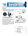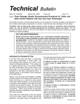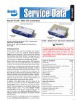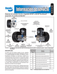
1
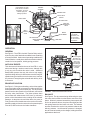
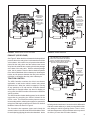
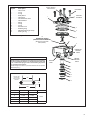
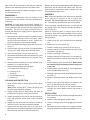
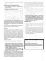
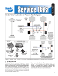
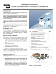
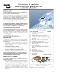
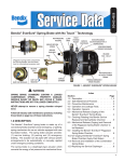
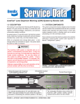
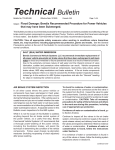
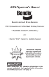
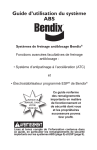
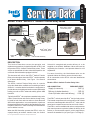
SD-13-4861
Bendix® ATR-6™ and ATR-3™ Antilock Traction Relay Valves
Bendix® ATR-3™ Antilock
Traction Relay Valves
2 PIN
SOLENOID
CONNECTOR
CONTROL
SOLENOID
CONTROL
PORT
COVER
Bendix® ATR-6™ Antilock
Traction Relay Valves
SUPPLY
PORT
DELIVERY PORTS (6)
FIGURE 1 - BENDIX® ATR-6™ (AND ATR-3™) ANTILOCK TRACTION RELAY VALVES
DESCRIPTION
This Service Data sheet covers the operation, and
replacement procedures, for both the Bendix® ATR-6™ and
the previous ATR-3™ Antilock Traction Relay valves. These
valves are specialized air brake valves developed for use
on Bendix antilock/traction-equipped vehicles.
This document will refer to the ATR-6™ Antilock Traction
Relay valve throughout since the ATR-3™ version operates
in an almost identical way. See Figure 1 for external
differences.
The ATR-6™ Antilock Traction Relay valve is a service
relay valve fitted with a modified cover containing a Control
Solenoid. It contains both air and electric components to
provide the service braking and traction control (differential
braking) as well as ESP® advanced stability system ABS
functions.
Typically the ATR-6™ valve replaces a standard relay valve
used to control the rear axle service brakes, though it may
be used for both front and rear axles on some advanced
ABS vehicle applications. In normal operation, it performs
the standard relay function and like the standard relay valve
it replaces, the ATR-6™ valve is normally mounted near the
service brakes it serves.
When the ABS Controller operates the ATR-6™ valve, for
example during an antilock traction event, the Control
ESP® is a registered trademark of Daimler and is used by BCVS under license.
Solenoid is energized and permits delivery air to be
supplied to the Antilock Modulator Valves and used as
required by the Controller - see Operation below for a full
explanation.
For ease of servicing, the inlet/exhaust valve can be
replaced without the need to remove the entire valve.
All air connections on the ATR-6™ valve are identified as
shown below.
Bendix® ATR-6™ Antilock Traction Relay Valve
AIR CONNECTION
EMBOSSED IDENT.
Supply (to reservoir) . . . . . . . . . . . . . . . . . SUP (1)
Delivery (to brake chamber) . . . . . . . . . . DEL (2)
Control (to brake valve rear delivery) . . CON (4)
The ATR-6™ valve is part of the R-12™ family of relay valves.
The internal components of the relay portion of all of these
valves are interchangeable with the R-12™ valve and the
same basic components are used to service all of them.
The ATR-6™ valve is available with various crack pressures
(the control pressure required to initiate air delivery to the
brakes) to accommodate specific vehicle applications;
however the standard is 4 psi (see Figure 7 on Page 5).
Control Shuttle. The small
piston (shown in its normal
rest position). The arrow
indicates spring force
holding it in position.
BRAKE PEDAL
CONTROL
SOLENOID
CONTROL PORT
RELAY VALVE
PISTON
SUPPLY PORT
DELIVERY PORT
ANTILOCK
MODULATOR
VALVE
INLET /
EXHAUST
VALVE
BRAKE
CHAMBER
RESERVOIR
VALVE EXHAUST
WHEEL SPEED
SENSOR
TONE RING
Diagram shows
a rear brake
application, but
this valve may
also be used for
front brakes
FIGURE 2 - SECTIONAL ATR-6™ ANTILOCK TRACTION ASSEMBLY
OPERATION
GENERAL
See Figure 2. The ATR-6™ Antilock Traction Relay valve is
a service relay valve fitted with a modified cover containing
a Control Solenoid. Under normal operating conditions the
Control Shuttle, a small piston within the traction solenoid,
remains in its rest position, held by spring pressure.
The driver applies
the brakes. The
piston in the relay
valve moves
down allowing
the waiting air
pressure to pass
to the brake
chambers
ANTILOCK EVENTS
This document will describe the use of the ATR-6™ valve
when used during a traction control event, although this
is only one role for which this valve is used. Advanced
Bendix ABS systems also use this valve to help supply
specific braking delivery for ABS events at a wider range of
speeds than typical traction control events occur, however
the process of energizing the solenoid and delivery of air
is the same.
RESERVOIR
BRAKE APPLICATION
See Figure 3. During normal braking, as the driver applies
force to the brake pedal, air pressure is delivered from the
brake pedal to the relay valve control port. The air pressure
passes into the valve, past the Control Shuttle, and moves
the relay valve piston down. The piston pushes down
and contacts the exhaust seat of the inner (or ‘exhaust’)
portion of the inlet/exhaust valve, sealing off the exhaust
passage. As the piston moves further down, the outer (or
‘inlet’) portion of the inlet/exhaust valve moves off its seat,
permitting supply air from the reservoir to flow past the open
inlet valve, and into the service brake chambers.
2
BRAKE
CHAMBER
FIGURE 3 - SERVICE BRAKE APPLICATION
BALANCE
See Figure 4. The air pressure being delivered by the open
inlet valve also is effective on the bottom area of the relay
piston. When air pressure beneath the piston equals the
service air pressure above, the piston lifts slightly and the
inlet spring returns the inlet valve to its seat. The exhaust
remains closed as the service line pressure balances the
delivery pressure. As delivered air pressure is changed,
the valve reacts instantly to the change, holding the brake
application at that level.
The pressure
under the piston
equals the
pressure above.
The piston lifts
slightly - the
exhaust remains
closed.
FIGURE 4 - BRAKE APPLICATION HOLDING
EXHAUST (OR RELEASE)
See Figure 5. When the driver releases the brake pedal, air
pressure above the relay piston is exhausted at the brake
valve exhaust. At the same time, air pressure beneath the
piston lifts the relay piston and the exhaust seat moves
away from the exhaust valve, opening the exhaust passage
at the base of the relay valve. With the exhaust passage
open, the air pressure from the brake chambers passes
to the Antilock Modulator Valve exhaust port, releasing the
brakes, and air pressure between the relay valve and the
modulator is released at the relay valve exhaust port.
The driver
releases the
brakes. The
piston in the relay
valve moves
up, closing the
delivery, and
opening the
exhaust.
FIGURE 5 - BRAKE RELEASE
The small piston moves to its energized
position. The arrow indicates the direction
it moves. The antilock traction Controller
energizes the solenoid, applying full reservoir
pressure to the antilock modulators.
The Controller
selects the
antilock
modulator to
deliver air to the
brake chamber
TRACTION CONTROL
The ABS Controller monitors the driver’s accelerator
application, as well as the vehicle’s motion using wheel
speed sensors. When the vehicle is stopped, or moving
at any speed up to 25 mph and the Controller detects
wheel spin, for example where one wheel is slipping on
an icy patch, the ABS Controller will intervene to assist the
vehicle’s traction.
The ABS Controller obtains braking power for the traction
intervention by energizing the Control Solenoid in the
ATR-6™ valve. This causes the traction piston to move to
its secondary position, allowing the supply air to operate the
relay piston and supply air pressure to each of its Antilock
Modulator Valves as shown in Figure 6.
The Controller then operates (opens and closes) the
solenoid valves in the individual Antilock Modulator Valve
for each spinning (slipping) wheel to slow that wheel. As the
FIGURE 6 - TRACTION APPLICATION
spinning wheel slows down, it forces the vehicle differential
to drive the other stationary, or slowly-turning wheel on that
axle, aiding the vehicle in gaining traction. Note: in some
vehicle arrangements a single modulator valve may control
air delivery to more than one brake chamber.
3
For a full description of antilock operation refer to the
appropriate Service Data Sheet covering the Electronic
Controller used on the vehicle. (Note: Service Data Sheets
are available for download from www.bendix.com.)
5. Following the vehicle manufacturer’s recommended
procedures, deactivate the electrical system in a
manner that safely removes all electrical power from
the vehicle.
PREVENTIVE MAINTENANCE
6. Never exceed manufacturer ’s recommended
pressures.
Important: Review the Bendix Warranty Policy before
performing any intrusive maintenance procedures. A
warranty may be voided if intrusive maintenance is
performed during the warranty period.
No two vehicles operate under identical conditions, as a
result, maintenance intervals may vary. Experience is a
valuable guide in determining the best maintenance interval
for air brake system components. At a minimum, the valve
should be inspected every 6 months or 1500 operating
hours, whichever comes first, for proper operation. Should
the valve not meet the standards of the operational tests
noted in this document, further investigation and service
of the valve may be required.
GENERAL SAFETY GUIDELINES
7. Never connect or disconnect a hose or line containing
pressure; it may whip. Never remove a component or
plug unless you are certain all system pressure has
been depleted.
8. Use only genuine Bendix ® replacement parts,
components and kits. Replacement hardware, tubing,
hose, fittings, etc. must be of equivalent size, type
and strength as original equipment and be designed
specifically for such applications and systems.
9. Components with stripped threads or damaged parts
should be replaced rather than repaired. Do not
attempt repairs requiring machining or welding unless
specifically stated and approved by the vehicle and
component manufacturer.
WARNING! PLEASE READ AND FOLLOW
THESE INSTRUCTIONS TO AVOID PERSONAL
INJURY OR DEATH:
10. Prior to returning the vehicle to service, make certain all
components and systems are restored to their proper
operating condition.
When working on or around a vehicle, the
following general precautions should be observed
at all times.
11. For vehicles with Antilock Traction Control (ATC),
the ATC function must be disabled (ATC indicator
lamp should be ON) prior to performing any vehicle
maintenance where one or more wheels on a drive
axle are lifted off the ground and moving.
1. Park the vehicle on a level surface, apply the parking
brakes, and always block the wheels. Always wear
safety glasses.
2. Stop the engine and remove ignition key when working
under or around the vehicle. When working in the engine
compartment, the engine should be shut off and the
ignition key should be removed. Where circumstances
require that the engine be in operation, EXTREME
CAUTION should be used to prevent personal injury
resulting from contact with moving, rotating, leaking,
heated or electrically charged components.
3. Do not attempt to install, remove, disassemble or
assemble a component until you have read and
thoroughly understand the recommended procedures.
Use only the proper tools and observe all precautions
pertaining to use of those tools.
4. If the work is being performed on the vehicle’s air brake
system, or any auxiliary pressurized air systems, make
certain to drain the air pressure from all reservoirs
before beginning ANY work on the vehicle. If the
vehicle is equipped with an AD-IS® air dryer system or
a dryer reservoir module, be sure to drain the purge
reservoir.
VEHICLE PREPARATION
1. Park the vehicle on a level surface and block the wheels
and/or hold the vehicle by means other than the air
brakes.
2. Drain the air pressure from all vehicle reservoirs.
REMOVAL AND INSTALLATION
Identify and mark or label all electrical wiring harnesses and
air hoses and their respective connections on the assembly
to facilitate ease of installation.
REMOVAL
1. If the entire valve is to be removed, identify air hoses
to facilitate installation. Prior to disassembly, remove
as much contamination as possible from the exterior of
the device taking care to keep all contamination from
entering the open ports.
2. Disconnect air hoses from valve*.
3. Disconnect the electrical connector from the traction
solenoid.
4. Remove valve from reservoir or if remotely mounted,
remove mounting bolts and then valve.
*It is generally not necessary to remove entire valve when
servicing only the inlet/exhaust valve. The inlet/exhaust
4
Key No.
1 .
2 .
3 .
4 .
5 .
6 .
7 .
8 .
9 .
10.
11.
12.
13.
14.
.
.
.
.
.
.
.
.
.
.
.
.
.
.
.
.
.
.
.
.
.
.
.
.
.
.
.
.
.
.
.
.
.
.
.
.
.
.
.
.
.
.
Washer Identifying
Crack Pressure
Description
.
.
.
.
.
.
.
.
.
.
.
.
.
.
. Valve Cover
. O-ring
. O-ring
. Relay Piston
. Valve Body
. Inlet & Exhaust Valve
. Valve Retainer
. Spring
. O-ring
. O-ring
. Exhaust Cover
. Retaining Ring
. Differential Spring (If Used)
. Sealing O-ring
CAP SCREW
TRACTION
SOLENOID
1
2
3
See Below for O-ring Identification Chart
13
DIFFERENTIAL SPRING
(CONTROLS CRACK PRESSURE*)
(Not used for most models.
See box below.)
4
14
5
HORIZONTAL
DELIVERY
PORTS
DIFFERENTIAL SPRINGS
*Crack Pressure is the amount of control pressure required by
the valve to initiate air delivery. For Crack Pressures other than
4 psi, a differential spring is used in the assembly to produce
the required valve response.
(Models designed to have a 4 psi Crack Pressure do not require a
differential spring.)
SUPPLY
PORT
6
VERTICAL
DELIVERY
PORTS
7
8
9
O-RING IDENTIFICATION
SECTIONAL SIDE
VIEW SHOWING
HOW AN O-RING IS
MEASURED.
10
11
I.D."
12
W
O.D."
Key
I.D.
O.D.
2
3.487
3.693
3
3.234
3.512
9
1.424
1.630
10
0.862
1.068
14
0.255
0.435
W
0.103
0.066
FIGURE 7 - ATR-6™ EXPLODED VIEW AND O-RING IDENTIFICATION
5
Caution: Drain all reservoirs before attempting to remove
the inlet exhaust valve.
Replace all parts not considered serviceable during these
inspections and all springs and rubber parts. Use only
genuine Bendix replacement parts, available from any
authorized Bendix parts outlet.
DISASSEMBLY
ASSEMBLY
Note: Prior to disassembly, mark the location of the
mounting bracket (not shown) to the cover and the cover
to the body.
Note: All torques specified in this document are assembly
torque and can be expected to fall off slightly after
assembly. Do not re-torque after initial assembly torque
fall. For assembly, hand wrenches are recommended.
valve insert can be removed by removing the snap ring,
exhaust cover assembly and then inlet/exhaust valve.
CAUTION: The valve body may be lightly clamped in a
bench vise during disassembly, however, over-clamping will
result in damage to the valve and result in leakage and/or
malfunction. If a vise is to be used, position the valve so
that the jaws bear on the supply ports on opposing sides
of the valve’s body.
1. Remove the four cap screws (and I.D. washer) securing
the mounting bracket and cover to the body. Retain
the cap screws and washer for reuse. Remove the
electrical connection to the traction solenoid.
Prior to assembly, lubricate all O-rings, O-ring bores and
any sliding surface with a silicone lubricant equivalent to
Dow Corning #10.
Wash all remaining parts in mineral spirits and dry
thoroughly. Using the lubricant provided in this kit, lightly
lubricate all O-rings, O-ring grooves, body bores and any
sliding surfaces.
1. Install O-rings (9 & 10) in the exhaust cover assembly
(11).
2. Remove and discard sealing rings (2 and 14) from the
cover (1).
2. Install O-ring (3) on the piston (4).
3. Remove piston (4) from the body (5) [and differential
spring (13) if used]. Retain these items for reuse.
4. Install the retainer (7) on the inlet exhaust valve (6) and
insert both in the body (5).
4. Remove and discard O-ring (3) from piston (4).
5. Install the spring (8) in the body (5).
5. Depress and hold the exhaust cover assembly (11) and
remove and discard retaining ring (12) from the valve
body (5).
6. Install the exhaust cover assembly (11) in the body (5).
Depress and hold the exhaust cover assembly in the
body.
6. Slowly release the holding force on the exhaust cover
assembly (11) to relax the spring.
7. Install retaining ring (12) in the body (5). Make certain
the retaining ring is completely seated in the groove
in the body.
7. Remove and discard the following parts:
a. Exhaust cover assembly (11)
b. O-rings (9 & 10)
c. Spring (8)
d. Inlet exhaust valve (6)
e. Retainer (7)
CLEANING AND INSPECTION
1. Wash all metal parts in mineral spirits and dry them
thoroughly.
(Note: When servicing R-12® valves, all springs and
all rubber parts should be replaced.)
2. Inspect all metal parts for deterioration and wear, as
evidenced by scratches, scoring and corrosion.
3. Install the sealing rings (2 and 14) on the cover (1).
8. Install the piston (4) in the body (5). Where applicable,
re-use the differential spring (13).
9. Referring to the marks made during disassembly, install
the cover (1).
10. Install the mounting bracket (not shown) on the cover
(1).
11. Install the four cap screws with the I.D. washer in the
cover (1) and torque to 80-100 inch pounds.
12. Test the valve as outlined in the Operational and
Leakage Test section before returning the vehicle to
service.
INSTALLATION
3. Inspect the exhaust valve seat on the relay piston for
nicks and scratches which could cause excessive
leakage.
1. Clean and inspect all air hoses for damage and replace
as necessary.
4. Inspect the inlet valve seat in the body for scratches
and nicks, which could cause excessive leakage.
3. Connect air hoses to the valve (plugging any unused
ports).
5. Inspect the check valve seat in the R-12® valve cover
and make sure all internal air passages in this area are
open and clean and free of nicks and scratches.
4. Reconnect the wire harness to the traction solenoid
using the identification made during REMOVAL step.
6
2. Install the valve and tighten mounting bolts.
5. Test valve as outlined in Operational and Leakage
Tests.
OPERATIONAL AND LEAKAGE TESTS
1. Chock the wheels, fully charge air brake system and
adjust the brakes.
2. Make several brake applications and check for prompt
application and release at each wheel.
3. Check for inlet valve and O-ring leakage. Make this
check with the service brakes released. Coat the
exhaust port and the area around the retaining ring
with a soap solution; leakage of a one-inch bubble in
3 seconds is permitted.
4. Check for exhaust valve leakage. Make this check with
the service brakes fully applied. Coat the outside of
the valve where the cover joins the body to check for
seal ring leakage; no leakage is permitted.
If the valve does not function as described above, or if the
leakage is excessive, it is recommended that the valve be
replaced with new or remanufactured units or repaired with
genuine Bendix parts, available at any authorized Bendix
parts outlet.
Refer to the Antilock Traction Controller Service Data sheet
for operational test for traction functionality.
GENERAL
A change in vehicle braking characteristics or a low
pressure warning may indicate a malfunction in one or
the other brake circuit, and although the vehicle air brake
system may continue to function, the vehicle should not
be operated until the necessary repairs have been made
and both braking circuits, including the pneumatic and
mechanical devices, are operating normally. Always
check the vehicle brake system for proper operation after
performing brake work and before returning the vehicle
to service.
specified for the ATR-6™ valve’s part number (also shown
on the I.D. washer installed on one of the cap screws).
NOTE: For ATR-6™ valves not incorporating a relay piston
return spring (13), the measured differential should be
approximately 4 psi. When a spring is in use, the differential
will be higher.
2. Disconnect the ATR-6 ™ valve’s two pin solenoid
connector from the Controller wire harness. Apply the
probes of a volt-ohm meter to the connector leading
to the solenoid and note the resistance of the solenoid
is between 15 and 17 ohms. If resistance other than
this is found, replace the ATR-6™ valve.
3. Apply and remove vehicle power (12 VDC) to the
two pin connector half leading to the ATR-6™ valve’s
(solenoid) while observing the brake chambers. Note
that a brake application is made and held while power
is applied to the ATR-6™ valve’s solenoid and that it is
released when power is removed.
LEAKAGE TESTS
1. Build the air system pressure to governor cutout. Apply
a soap solution to the exhaust port. The leakage noted
should not exceed a one-inch bubble in less than 3
seconds.
2. Make and hold a full brake application and apply a soap
solution to the exhaust port and around the cover where
it joins the body. The leakage noted should not exceed
a one-inch bubble in less than 3 seconds at the exhaust
port. If the ATR-6™ valve fails to function as described,
or leakage is excessive, it should be replaced with a
new or genuine Bendix unit.
OPERATION TEST
BENDIX TECHNICAL ASSISTANCE TEAM
1. Apply and release the brakes several times and check
for prompt application and release at each wheel.
For direct telephone technical support, call the Bendix
Tech Team at:
If an incomplete or sluggish release of the brakes is
noted at some, but not all wheels, test the Antilock
Modulator Valve(s) operating those wheels for proper
operation, and inspect for kinked or obstructed air hose
leading to, or from, the Modulator(s).
1-800-AIR-BRAKE (1-800-247-2725),
Monday through Friday, 8:00 A.M. to 6:00 P.M. EST,
and follow the instructions in the recorded message.
Or, you may e-mail: [email protected]
If an incomplete or sluggish release is noted at all
wheels, inspect for kinked or obstructed air hose
leading to, or from, the ATR-6™ valve.
Note: The ATR-6™ valve’s Crack Pressure differential can
be checked by applying 10 psi to the service port and noting
the pressure registered at the delivery port with a gauge
of known accuracy. Subtract the delivery port pressure
from the 10 psi service pressure to obtain the differential.
Compare the measured differential with the Crack Pressure
7
8
BW2598 © 2008 Bendix Commercial Vehicle Systems LLC. All Rights Reserved. 4/08 Printed in U.S.A.