1
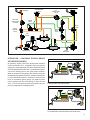
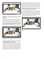
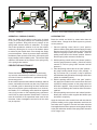
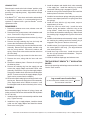
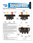
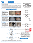
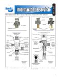
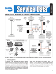
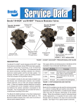
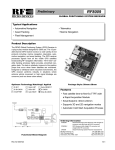
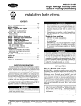
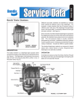
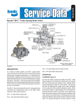
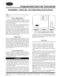
SD-03-4504
Bendix® R-7™ Modulating Valve
EXHAUST
EXHAUST
CONTROL
PORT
MOUNTING
HOLE (2)
INLET
VALVE
SPRING
BALANCE PORT
INLET
EXHAUST
VALVE
MOUNTING
SURFACE
INLET
VALVE
SEAT
DELIVERY (2)
SUPPLY PORT
MOUNTING
HOLE (2)
BALANCE
PISTON
INNER SPRING
SUPPLY
CONTROL
PORT
CONTROL
PISTON
DOUBLE CHECK
VALVE
(SUPPLY PORT &
BALANCE PORT)
SINGLE
CHECK
VALVE
DELIVERY
PORT (2)
OUTER SPRING
BALANCE
INVERTED R-7™ VALVE
CONTROL
Some early versions
featured an adjusting screw
EXHAUST
FIGURE 1 - EXTERIOR & SECTIONAL VIEW.
INSET FIGURE 2 - INVERTED VIEW
DESCRIPTION
The Bendix® R‑7™ modulating valve is used in conjunction
with a dual air brake system and spring brake actuators.
Typically the R‑7 modulating valve performs four functions:
1. Limits hold‑off pressure to the spring brake actuators.
The valve has one 1/4" control, one 3/8" supply, one 1/4"
balance, two 3/8" delivery NPTF ports, and an exhaust
port protected by an exhaust diaphragm. The valve
incorporates two 13/32" holes for mounting.
2. Provides a quick release of air pressure from the spring
cavity of the spring brake actuator allowing a fast
application of the spring brake actuators. The valve
delivers air to the park brake quick release valve (or
relay) and also releases air in the control line to the
quick release valve (or relay).
Note for model year 2001 and later International®
Trucks only: There is an inverted R-7 valve, which
appears inverted from the other pictures in this document.
A standard R-7 valve and an inverted R-7 valve are not
interchangeable. See Figure 2 for a picture of an inverted
R-7 valve.
3. Modulates spring brake actuator application should a
failure occur in the primary service brake system.
4. Prevents compounding of service and spring forces.
1
GENERAL SAFETY GUIDELINES
WARNING! PLEASE READ AND FOLLOW THESE INSTRUCTIONS
TO AVOID PERSONAL INJURY OR DEATH:
When working on or around a vehicle, the following guidelines should be observed AT ALL TIMES:
▲ Park the vehicle on a level surface, apply the
parking brakes and always block the wheels.
Always wear personal protection equipment.
▲ Stop the engine and remove the ignition key
when working under or around the vehicle.
When working in the engine compartment,
the engine should be shut off and the ignition
key should be removed. Where circumstances
require that the engine be in operation, EXTREME
CAUTION should be used to prevent personal
injury resulting from contact with moving,
rotating, leaking, heated or electrically-charged
components.
▲ Do not attempt to install, remove, disassemble
or assemble a component until you have read,
and thoroughly understand, the recommended
procedures. Use only the proper tools and
observe all precautions pertaining to use of those
tools.
▲ If the work is being performed on the vehicle’s
air brake system, or any auxiliary pressurized air
systems, make certain to drain the air pressure
from all reservoirs before beginning ANY work
on the vehicle. If the vehicle is equipped with a
Bendix® AD-IS® air dryer system, a Bendix® DRM™
dryer reservoir module, or a Bendix® AD-9si™ air
dryer, be sure to drain the purge reservoir.
▲ F o l l o w i n g t h e v e h i c l e m a n u f a c t u r e r ’s
recommended procedures, deactivate the
electrical system in a manner that safely removes
all electrical power from the vehicle.
▲ Never exceed manufacturer’s recommended
pressures.
▲ Never connect or disconnect a hose or line
containing pressure; it may whip. Never remove
a component or plug unless you are certain all
system pressure has been depleted.
▲ Use only genuine Bendix ® brand replacement
parts, components and kits. Replacement
hardware, tubing, hose, fittings, etc. must be of
equivalent size, type and strength as original
equipment and be designed specifically for such
applications and systems.
▲ Components with stripped threads or damaged
parts should be replaced rather than repaired.
Do not attempt repairs requiring machining or
welding unless specifically stated and approved
by the vehicle and component manufacturer.
▲ Prior to returning the vehicle to service, make
certain all components and systems are restored
to their proper operating condition.
▲ For vehicles with Automatic Traction Control
(ATC), the ATC function must be disabled (ATC
indicator lamp should be ON) prior to performing
any vehicle maintenance where one or more
wheels on a drive axle are lifted off the ground
and moving.
▲ The power MUST be temporarily disconnected
from the radar sensor whenever any tests USING
A DYNAMOMETER are conducted on a Bendix®
Wingman® Advanced™-equipped vehicle.
▲ You should consult the vehicle manufacturer's operating and service manuals, and any related literature,
in conjunction with the Guidelines above.
2
BRAKE
CHAMBER
ANTILOCK
MODULATOR
- 4 PLACES
PARK CONTROL
VALVE
R-7™
MODULATING
VALVE
BRAKE
VALVE
RELAY
VALVE
QUICK
RELEASE
VALVE
RELAY
VALVE
AIR
DRYER
FRONT AXLE
Bendix
SUPPLY
COMPRESSOR
REAR AXLE
SLACK
ADJUSTER
FIGURE 3 - TYPICAL SYSTEM SCHEMATIC
OPERATION ‑ CHARGING SPRING BRAKE
ACTUATORS (FIGURE 3)
Air pressure used to control the spring brake actuators
enters the Bendix® R-7™ modulating valve through the
supply port, passing through one side of the double check
valve, through the open inlet valve, over the balance piston,
and out the delivery ports to the spring brake actuators.
When air pressure in the spring brake actuator cavity has
released the spring brake actuators—and when air pressure
on top of the balance piston is sufficient to overcome the
force of the balance piston spring—the balance piston
moves, allowing the inlet valve spring to close the inlet
valve. This in turn, shuts off further air pressure from the
reservoir supplying the modulating valve.
FIGURE 3A - CHARGING - PARKING BRAKE SUPPLY LESS
THAN BALANCE PISTON SETTING
FIGURE 3B - CHARGING - PARKING BRAKE SUPPLY EQUAL
TO OR GREATER THAN BALANCE PISTON SETTING
3
The pressure differential between the primary and
secondary circuits regulates the amount of air pressure
released from the spring cavity of the spring brake actuator.
This results in a total brake application on the rear axle
which is proportionate to the braking on the other axles.
OPERATION ‑ SERVICE APPLICATION WITH LOSS OF
AIR IN SECONDARY CIRCUIT (FIGURE 6)
FIGURE 4 - NORMAL SERVICE APPLICATION
A service application made with a loss of air in the
secondary circuit would result in less, or no, air delivered to
the top of the control piston. However, the piston would not
move and braking on the rear axle(s) is assured because
the primary circuit supplies rear axle service brakes. The
spring brake actuators will not be actuated.
OPERATION ‑ NORMAL SERVICE APPLICATION
(FIGURE 4)
When a service application is made by actuating the dual
brake valve, air from the primary circuit is delivered to the
lower side of the control piston through the balance port,
and air from the secondary circuit is delivered to the top
of the control piston through the control port. Because air
pressure from the primary and secondary circuits are not
equal, there will be a slight movement of the control piston.
FIGURE 6 - SERVICE APPLICATION LOSS OF SECONDARY
CIRCUIT
FIGURE 5 - SERVICE APPLICATION LOSS OF PRIMARY
CIRCUIT
OPERATION ‑ SERVICE APPLICATION WITH LOSS OF
AIR IN PRIMARY CIRCUIT (FIGURE 5)
A service application made with a loss of air in the primary
circuit would result in reduced air pressure delivered to
the lower area of the control piston. Air pressure from the
secondary circuit on top of the control piston would force
the piston down, opening the exhaust valve and allowing air
pressure in the spring cavity of the spring brake actuator to
release and the spring brake actuator to apply the brakes.
4
FIGURE 7 - PARKING
FIGURE 8 - ANTI-COMPOUNDING WHILE PARKING
OPERATION ‑ PARKING (FIGURE 7)
OPERATING TEST
When the handle of the parking control valve is placed
in the “park” (exhaust) position, the modulating valve’s
supply air pressure, along with the air pressure in the
spring brake actuator cavities is exhausted. The single
check valve speeds the exhaust of air from the actuator
cavities by allowing the air on top of the balance piston
to exhaust by the double check valve through the supply
port to atmosphere. When air pressure drops sufficiently,
the balance piston opens the inlet valve, thus opening the
larger passage in the modulating valve. This ensures rapid
exhaust of the balance of air pressure in the spring cavity
of the spring brake actuator.
Block the vehicle and hold it by means other than the
vehicle brakes. Charge the air brake system to governor
cut‑out pressure.
PREVENTIVE MAINTENANCE
IMPORTANT
Review the Bendix Warranty Policy before performing
any intrusive maintenance procedures. A warranty may
be voided if intrusive maintenance is performed during
the warranty period.
No two vehicles operate under identical conditions, and that
means, maintenance intervals may also vary. Experience
is a valuable guide in determining the best maintenance
interval for air brake system components. At a minimum,
the Bendix® R-7™ modulating valve should be inspected
every six (6) months or 1500 operating hours, whichever
comes first, for proper operation. Should the R-7 valve not
meet the elements of the operational tests noted in this
document, further investigation and service of the valve
may be required.
1. Place the parking control valve in “park” position.
Observe that the spring brake actuators apply promptly.
Remove the air line from the delivery port of valve and
install a test gauge known to be accurate. Place the
parking control valve in the “release” position. Observe
that the spring brake actuators release fully.
2. With the parking control valve in the “release” position,
note the gauge pressure reading. (Check the vehicle
manual for correct spring brake actuator hold‑off
pressure.)
3. Place the parking control valve in the “park” position—
the gauge reading should drop to zero promptly. A
lag—more than one (1) second—in drop of pressure
would indicate faulty operation of the single check valve
(within the modulating valve).
4. With the parking control valve in the “park” position,
fully apply the foot brake valve several times and note
a pressure reading increase on the gauge each time
the brake is applied. If the pressure reading does not
occur, the modulating valve must be either serviced or
replaced.
5. Place the parking control valve in the “release” position.
Identify the reservoir which supplies the balance port
and drain it completely.
Apply the foot brake valve several times and note that the
pressure reading on the gauge decreases each time the
foot brake valve is applied. After the foot brake valve has
been applied several times, pressure on the gauge will drop
to the point where the release of the spring brake actuators
will no longer occur.
5
LEAKAGE TEST
Place the park control valve in the “release” position; using
a soap solution, coat the exhaust and vent hole (in the
proximity of the adjusting screw). Slight bubble leakage
is permitted.
If the Bendix® R-7™ valve does not function as described,
or if leakage is excessive, it is recommended that it be
repaired or replaced with a genuine Bendix® service
replacement valve.
DISASSEMBLY
1. Remove the exhaust cover screw, exhaust cover and
exhaust diaphragm.
2. Remove the four (4) cap screws, and lockwashers and
cover. Remove the o‑ring from the cover.
3. Remove the control piston and remove three (3) o‑rings
from the control piston.
4. Remove the large retaining ring from the body and
remove the inlet/exhaust valve assembly.
5. Remove the retaining ring from the inlet/exhaust valve
assembly. Remove the o‑ring retainer, and the o‑ring
from the o‑ring retainer. Remove the washer and
spring. Remove the valve retainer and the valve from
the valve body.
6. Remove the four (4) cap screws from the other cover.
7. Remove the cover, along with the inner and outer
springs.
8. Remove the balance piston. Remove the o‑ring from
the balance piston.
9. Remove the retaining ring from the supply port and
remove the supply adapter and double check valve
assembly. Remove the o‑ring from the supply adapter.
Remove the double check valve from the shuttle guide.
(NOTE: To ease removal of the supply adapter, a pipe
nipple can be screwed into the adapter.)
10.Remove the Allen head plug from the single check valve
service port. Remove the single check valve assembly.
(If the single check valve is difficult to remove, it can
be dislodged inside the bore of the body of the valve).
3. Install the adapter and double check valve assembly
in the supply port. Install the retaining ring, making
certain the retaining ring is engaged in groove.
4. Install the o‑ring on the balance piston then install the
balance piston in the bore of the body.
5. Install the inner and outer springs and spring seat (note
that the cone shaped protrusion on spring seat faces
the springs).
6. Install the cover with four (4) cap screws, torque to
approximately 45 in-lbs.
7. Install the valve on valve body. Install the valve
retainer, spring, and washer. Install the o-ring on the
o-ring retainer. Install the o-ring retainer, compress
the retainer and install the retaining ring. Make certain
the retaining ring is engaged in the groove of the valve
body.
8. Install the inlet/exhaust valve assembly in body. Install
the retaining ring making certain the retaining ring is
engaged in the groove in the bore of the body.
9. Install the three (3) o‑rings on the control piston. Install
the control piston in the body. (The larger diameter
stem should point up).
10.Install the o‑ring on the cover. Install the cover with
the four (4) cap screws and lockwashers. Torque to
approximately 100 in-lbs.
11.Install the exhaust diaphragm and exhaust cover.
TESTING REBUILT BENDIX® R‑7™ MODULATING
VALVES
Perform the operating and leakage tests as outlined in the
“Service Tests” section.
Log-on and Learn from the Best
On-line training that's available when you are
Visit www.brake-school.com.
24/7/365.
ASSEMBLY
Before assembly, lightly lubricate all o‑rings, bores and
mating surfaces with silicone lubricant BW-650-M (Bendix
Pc. No. 291126).
1. Install the single check valve assembly and Allen head
plug. Tighten securely.
2. Install the o‑ring on supply adapter, install the shuttle
guide over the supply adapter and install the double
check valve in the guide.
SD-03-4504 © 2014 Bendix Commercial Vehicle Systems LLC, a member of the Knorr-Bremse Group • 05/14 • All Rights Reserved.
6