1
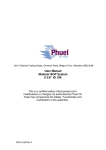
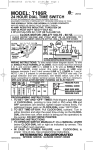
SD-03-3613
®
Bendix® PP-3™ Trailer Supply Valve
DESCRIPTION
BUTTON
MOUNTING
NUT
SUPPLY
PORT
The PP-3™ trailer supply valve, installed in the cab, operates
in conjunction with a TP-3™ tractor protection valve to supply
air under pressure to the trailer and protect the tractor air
supply in case of a break-away or an air leak on the trailer
which would reduce the pressure in the trailer supply line
below the design trip point of the PP-3™ valve.
With reference to Figure 2 the supply port of the PP-3™
valve is supplied from the towing vehicle reservoir. Its
delivery goes directly to the supply port on the TP-3™ tractor
protection valve.
OPERATION
DELIVERY
PORT
FIGURE 1 - PP-3™ TRAILER SUPPLY VALVE EXTERIOR
PP-3™
CONTROL
VALVE
TC-2™ VALVE
The PP-3™ control valve is a push-pull operated valve. The
button must be pushed in to open the valve. The button will
not stay in unless there is 50 psi or more in the supply line.
Once the pressure is enough that the button will remain in,
air flows through the tractor protection valve to the trailer.
DOUBLE
CHECK
VALVE
TP-3™
TRACTOR
PROTECTION
VALVE
TRAILER
EMERGENCY LINE
TRAILER SERVICE
LINE
BRAKE
VALVE
COMPRESSOR
NO. 1
RESERVOIR
NO. 2
RESERVOIR
FIGURE 2
1
that no air escapes at the open trailer service hose
coupling.
If, in the case of an emergency or for some other reason the
driver wishes an application of the trailer brakes, he pulls
the PP-3™ valve control button out. Emergency line pressure
will exhaust out the PP-3™ valve exhaust port causing an
application of the trailer brakes. Also, the TP-3™ inlet valve
seats and closes the service line. The PP-3™ valve button is
pulled out and left out during bob-tailed operation of the tractor.
In normal use the button is pulled out before uncoupling
from the trailer and pushed in after coupling to the trailer.
5. When system pressure reaches approximately 60 psi,
the PP-3™ valve button should be pushed in. System
pressure should show at once on the test gauge
connected in the emergency line and the button of the
PP-3™ valve should remain in without being held.
Should a condition occur resulting in air loss from the tractor
or trailer system through leakage and the driver fails to
manually pull out the PP-3™ valve button, the PP-3™ valve
will automatically close at approximately 40 psi and seal
the tractor air lines. The driver cannot, in this condition,
overcome the emergency application of the trailer brakes by
holding the PP-3™ valve button in. If the driver should hold
the button in as emergency line pressure bleeds down from
the 40 psi range to approximately 30 psi, the tripper piston
will move and open the tripper exhaust in the PP-3™ valve.
Emergency line air will exhaust through the tripper exhaust
and hold the trailer brakes applied.
7. With PP-3™ valve button still in, check for leakage at
PP-3™ valve exhaust and tripper exhaust ports. Leakage
should not exceed a 1" bubble in 5 seconds at either
point.
PREVENTIVE MAINTENANCE
Important: Review the Bendix Warranty Policy before
performing any intrusive maintenance procedures. A warranty
may be voided if intrusive maintenance is performed during
the warranty period.
No two vehicles operate under identical conditions, as a
result, maintenance intervals may vary. Experience is a
valuable guide in determining the best maintenance interval
for air brake system components. At a minimum, the PP-3™
valve should be inspected every 12 months or 3600 operating
hours, whichever comes first, for proper operation. Should
the PP-3™ valve not meet the elements of the operational
tests noted in this document, further investigation and service
of the valve may be required.
OPERATING AND LEAKAGE CHECKS
To make the following operating and leakage checks, an
accurate test gauge installed in a spare hose coupling is
required. The vehicle dash gauge should be checked for
accuracy against the test gauge prior to making these tests.
1. Block and/or hold the vehicle by a means other than air
brakes during these tests.
2. Drain vehicle reservoir supply, then close drain cocks.
3. Connect assembled hose coupling and test gauge in
tractor emergency hose coupling. Start engine and build
up system pressure.
4. As reservoir pressure builds up there should be no
pressure reading on test gauge. When system pressure
reaches the 30 to 40 psi range on dash gauge make
and hold a foot or hand valve application and observe
2
6. Build system pressure up to approximately 100 psi, then
stop engine. With engine stopped, wait momentarily,
then notice that dash gauge and test gauge pressure
reading equal. While still in this position, make a foot or
hand valve application and observe that air is delivered
out the open trailer service coupling.
8. With PP-3™ valve button still in, check for leakage at the
TP-3™ valve exhaust and open service coupling. Leakage
should not be more than a 1" bubble in 5 seconds at
either point.
9. Pull the PP-3™ valve button out: pressure on the test
gauge connected in the emergency line should drop to
zero. Make and hold a hand valve application and observe
that air delivered at the open service coupling does not
exceed a 1" bubble in 5 seconds. Release foot or hand
valve application.
NOTE: If the PP-3™ valve does not function as described
or if leakage is excessive, it is recommended that it be
returned to the nearest Bendix authorized distributor for
a factory rebuilt valve. If this is not possible, the valve
should be repaired using genuine Bendix parts, in which
case the following should prove helpful.
REMOVING AND INSTALLING
REMOVING
1. Block and/or hold the vehicle by a means other than air
brakes. Drain air brake system.
2. Disconnect supply and delivery lines from PP-3™ valve.
3. Drive out PP-3™ valve button roll pin and remove button.
Remove PP-3™ valve mounting nut, then PP-3™ valve.
INSTALLING
When installing the PP-3™ valve, refer to Figure 2 for proper
connections along with following explanations:
1. Supply line from tractor reservoir is connected to supply
port of PP-3™ valve.
2. Delivery line from PP-3™ valve delivery port is connected
to tractor emergency port of TP-3™ valve.
3. PP-3™ valve exhaust port and tripper exhaust must be
open.
4. Two (2) ports marked “Del” on upper PP-3™ control valve
body are plugged and must remain plugged.
DISASSEMBLY
PP-3 PUSH-PULL VALVE
Inspect seats in upper and lower body for nicks and burrs.
Redress seats if damaged.
1. Button pin (1) Figure 3, button (2) and mounting nut (3)
are normally removed when valve is removed from
vehicle.
Inspect plunger and tripper piston bores in bodies and cover
for deep scratches or nicks. They should be smooth and
clean.
2. Remove two lower body cap screws (4) and lock washers,
then lower body (5) with cover (6).
Check springs for distortion, corrosion, and cracks.
3. Remove cover with tripper piston (7) from lower body.
Replace all parts not considered serviceable during these
inspections, especially o-rings and valves.
™
4. Remove tripper piston and spring (8) from cover.
5. Remove tripper piston and cover seal o-rings (9 & 10).
ASSEMBLY
6. Insert rod or punch in upper plunger pin hole and hold
plunger (11) from turning while inlet and exhaust valve
nut is removed.
Prior to assembly, lubricate o-rings and bearing surfaces
with silicone lubricant Bendix Pc. No. 291126.
7. Remove washer (13) and valve (14).
2. Position plunger spring (15) in upper body, then press
plunger (11) down inside spring in the body.
8. Pull plunger from upper body.
9. Remove plunger spring (15) and o-ring (16).
10. Remove upper body seal ring (17). Do not remove plugs
from ports marked “Del” in upper body.
CLEANING AND INSPECTION OF PARTS
Wash all metal parts in mineral spirits and then dry.
1. Install plunger o-ring (16).
3. Place inlet and exhaust valve (14), then washer (13),
over threaded, protruding end of plunger.
4. Install and tighten self-locking nut (12). Torque on the
nut should be 30 to 40 inch pounds.
5. Place upper and lower body seal o-ring (17) in place.
6. Install tripper piston o-ring (9).
In particular, make sure supply port in PP-3™ valve upper
body, tripper by-pass slot, and tripper exhaust port in cover
are thoroughly cleaned and unrestricted.
7. Position cover o-ring seal (10) on cover.
Inspect all parts for excessive wear or deterioration.
9. Place cover with tripper installed into lower body.
BUTTON (2)
SPRING (15)
SPIROL PIN (1)
10. Fasten lower body and cover assembly to upper
assembly with cap screws (4) and lockwashers. Tighten
cap screws evenly and securely.
PLUNGER (11)
TESTING REBUILT PP-3™ VALVE
NUT (3)
O-RING (16)
PIPE PLUG
SUPPLY
PORT
SEAL (17)
INLET AND
EXHAUST
VALVE (14)
INLET AND
EXHAUST
VALVE NUT
(12)
WASHER (13)
EXHAUST
PORT
DELIVERY
PORT
LOWER BODY
(5)
TRIPPER
PISTON (7)
O-RING (9)
O-RING (10)
COVER (6)
TRIPPER
EXHAUST
8. Position tripper spring (8) in cover (6) then press tripper
piston (7) down over spring and into the cover bore.
TRIPPER
SPRING (8)
CAP SCREW
(4)
Perform operating and leakage checks as outlined in previous
section.
WARNING! PLEASE READ AND FOLLOW
THESE INSTRUCTIONS TO AVOID
PERSONAL INJURY OR DEATH:
When working on or around a vehicle, the following
general precautions should be observed at all times.
1. Park the vehicle on a level surface, apply the
parking brakes, and always block the wheels.
Always wear safety glasses.
2. Stop the engine and remove ignition key when
working under or around the vehicle. When
working in the engine compartment, the engine
should be shut off and the ignition key should be
removed. Where circumstances require that the
engine be in operation, EXTREME CAUTION should
be used to prevent personal injury resulting from
contact with moving, rotating, leaking, heated or
electrically charged components.
FIGURE 3 - PP-3™ CONTROL VALVE
3
3. Do not attempt to install, remove, disassemble or
assemble a component until you have read and
thoroughly understand the recommended
procedures. Use only the proper tools and observe
all precautions pertaining to use of those tools.
4. If the work is being performed on the vehicle’s air
brake system, or any auxiliary pressurized air
systems, make certain to drain the air pressure from
all reservoirs before beginning ANY work on the
vehicle. If the vehicle is equipped with an AD-IS™
air dryer system or a dryer reservoir module, be
sure to drain the purge reservoir.
5. Following
the
vehicle
manufacturer’s
recommended procedures, deactivate the electrical
system in a manner that safely removes all
electrical power from the vehicle.
6. Never exceed manufacturer’s recommended
pressures.
4
7. Never connect or disconnect a hose or line
containing pressure; it may whip. Never remove a
component or plug unless you are certain all
system pressure has been depleted.
8. Use only genuine Bendix ® replacement parts,
components and kits. Replacement hardware,
tubing, hose, fittings, etc. must be of equivalent
size, type and strength as original equipment and
be designed specifically for such applications and
systems.
9. Components with stripped threads or damaged
parts should be replaced rather than repaired. Do
not attempt repairs requiring machining or welding
unless specifically stated and approved by the
vehicle and component manufacturer.
10. Prior to returning the vehicle to service, make
certain all components and systems are restored
to their proper operating condition.
BW1437 © 2004 Bendix Commercial Vehicle Systems LLC. All rights reserved. 3/2004 Printed in U.S.A.