1
Plastic Fiber Optic Assembly model PBPS26U
.02" diameter bifurcated fiber with side-view probe sensing end
PBPS26U
p/n 35042
(non-bendable)
Description
Non-bendable side-view probe sensing end
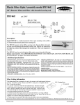
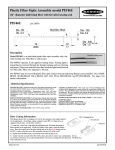
Model PBPS26U is a bifurcated plastic fiber optic assembly
with a 2-inch long non-bendable side-view probe type sensing
end. It is ideal for right-angle sensing in "tight" areas.
The PBPS26U operates in the diffuse sensing mode. Sensing
light is transmitted and received through an opening located
in the side of the sensing probe near the tip (see drawing and photo). Objects are detected by the light they reflect back through
the opening. Fiber core diameter is .02 inch. NOTE: The probe tip is non-bendable.
The PBPS26U may be used with plastic fiber optic sensors from the following Banner sensor families: D12, OMNI-BEAM,
MAXI-BEAM, VALU-BEAM, Q45, MINI-BEAM, and ECONO-BEAM. See page 2 for further information.
Additional Specifications
SENSING RANGE: A function of the sensor.
For further information, contact your factory applications engineer.
TEMPERATURE EXTREMES: Temperatures below -30°C will cause
embrittlement of the plastic materials but will not cause transmission loss.
Temperatures above +70°C will cause both transmission loss and fiber
shrinkage.
REPEAT BENDING/FLEXING: Life expectancy of plastic fiber optic cable
is in excess of one million cycles at bend radii of no less than the minimum
(stated at right) and a bend of 90 degrees or less. Avoid stress at the point where
the cable enters the sensor ("control end") and at the sensing end tip. Coiled
plastic fiberoptic assemblies are recommended for any application requiring
reciprocating fiber motion.
OPERATING TEMPERATURE: -30 to +70°C (-20 to +158°F).
CHEMICAL RESISTANCE: The acrylic core of the monofilament optical fiber will be damaged by contact with acids, strong bases (alkalis) and
solvents. The polyethylene jacket will protect the fiber from most chemical
environments. However, materials may migrate through the jacket with long
term exposure. Samples of fiber optic material are available from Banner for
testing and evaluation.
MINIMUM BEND RADIUS OF PLASTIC FIBER: 0.5 inch (12 mm).
The 2-inch long stainless steel side-view probe tip is non-bendable.
CONSTRUCTION:
OPTICAL FIBER: acrylic monofilament
PROTECTIVE JACKET: black polyethylene
PROBE END TIP: hardened (non-bendable) T304 stainless steel
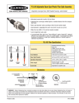
Fiber Cutting Information
This Banner plastic fiber is designed to be cut by the customer to the length required for the
application. To facilitate cutting, a Banner model PFC-1 cutting device is supplied
with this fiber. Cut the fiber as follows:
1) Locate the "control end" of the fiber (the unfinished end). Determine the length
of fiber required for the application. At the control end of the fiber, separate the two
fibers. Lift the top (blade) of the cutter to open the cutting ports. Insert one of the
control ends through one of the two small cutting ports on the PFC-1 cutter so that the
excess fiber protrudes from the back of the cutter.
2) Double-check the fiber length, and close the cutter until the fiber is cut. Using a different cutting port, cut the second control end to the same length as the first. Separate the cut ends for a length of
2 to 3 inches to allow proper attachment to the sensor.
3) Gently wipe the cut ends of the fiber with a clean, dry cloth to remove any contamination.
Do not use solvents or abrasives on any exposed optical fiber. Do not use a cutting port more than once. The blade may tend to dull after one cut.
Printed in USA
p/n 36377
Installation Instructions
D12 Series
D12 Series sensors for
use with plastic fiber optic
assemblies include sensors
with the letters FP in their
model number suffix.
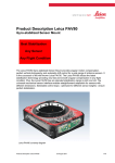
Install the plastic fiber optic assembly(s)
as follows:
1) Prepare the sensor ends of the fibers (see page 1, bottom).
2) Unlock (slide up) the fiber gripper and
insert the small fiber adaptor into the ports as far as it will go.
3) Gently insert the prepared plastic fiber sensor ends into the ports as far as they will go. Slide the fiber gripper down to lock.
OMNI-BEAM, MAXI-BEAM,
VALU-BEAM, Q45 Series
OMNI-BEAM, MAXIBEAM, VALU-BEAM,
and Q45 Series sensors for
use with plastic fiber optic
assemblies include sensors
with the letters FP in their
model number suffix.
Install the plastic fiber optic assembly(s)
as follows:
Prepare the sensor ends of the fibers (see page 1, bottom).
Loosen the clamp screw on the sensor face.
Follow steps 1-3 in the drawing, right.
MINI-BEAM, ECONO-BEAM
MINI-BEAM and ECONOBEAM sensors for use with
plastic fiber optic assemblies include sensors with
the letters FP in their model
number suffix.
Banner Engineering Corp.
Install the plastic fiber optic
assembly(s) as follows:
Prepare the sensor ends of the fibers (see page 1, bottom).
Loosen the clamp screw on the sensor face.
Follow steps 1-3 in the drawing, right.
9714 Tenth Ave. No., Minneapolis, MN 55441
Telephone: (612) 544-3164
FAX: (612) 544-3213