1
PT 3 series II
Preamplifier Tuner
Owner’s Manual
P/N 13010 REV 0005
P/N 13010 REV 0005
TABLE OF CONTENTS
Safety Precautions . . . . . . . . . . . . . . . . . . . . . . . . . . . . . . . . . . . . . . . . . . . . . . . . . . . . . . . . . . . . . . . . . . . . . . . . . . . . . . 1
Features . . . . . . . . . . . . . . . . . . . . . . . . . . . . . . . . . . . . . . . . . . . . . . . . . . . . . . . . . . . . . . . . . . . . . . . . . . . . . . . . . . . . . . . . 2
The Basics . . . . . . . . . . . . . . . . . . . . . . . . . . . . . . . . . . . . . . . . . . . . . . . . . . . . . . . . . . . . . . . . . . . . . . . . . . . . . . . . . . . . . . 3
Front Panel . . . . . . . . . . . . . . . . . . . . . . . . . . . . . . . . . . . . . . . . . . . . . . . . . . . . . . . . . . . . . . . . . . . . . . . . . . . . . . . . . . . . . . 4
Rear Panel . . . . . . . . . . . . . . . . . . . . . . . . . . . . . . . . . . . . . . . . . . . . . . . . . . . . . . . . . . . . . . . . . . . . . . . . . . . . . . . . . . . . . . 5
Remote Control . . . . . . . . . . . . . . . . . . . . . . . . . . . . . . . . . . . . . . . . . . . . . . . . . . . . . . . . . . . . . . . . . . . . . . . . . . . . . . . . . . 6
Making the connection . . . . . . . . . . . . . . . . . . . . . . . . . . . . . . . . . . . . . . . . . . . . . . . . . . . . . . . . . . . . . . . . . . . . . . . . . . . 7
Audio Connections . . . . . . . . . . . . . . . . . . . . . . . . . . . . . . . . . . . . . . . . . . . . . . . . . . . . . . . . . . . . . . . . . . . . . . . . . . . . 8
Using Full Range Speakers . . . . . . . . . . . . . . . . . . . . . . . . . . . . . . . . . . . . . . . . . . . . . . . . . . . . . . . . . . . . . . . . . . . . . 9
Using Small Speakers . . . . . . . . . . . . . . . . . . . . . . . . . . . . . . . . . . . . . . . . . . . . . . . . . . . . . . . . . . . . . . . . . . . . . . . . 10
Antenna Connections . . . . . . . . . . . . . . . . . . . . . . . . . . . . . . . . . . . . . . . . . . . . . . . . . . . . . . . . . . . . . . . . . . . . . . . . . 11
Control Output / IR Input . . . . . . . . . . . . . . . . . . . . . . . . . . . . . . . . . . . . . . . . . . . . . . . . . . . . . . . . . . . . . . . . . . . . . . . 11
Operation . . . . . . . . . . . . . . . . . . . . . . . . . . . . . . . . . . . . . . . . . . . . . . . . . . . . . . . . . . . . . . . . . . . . . . . . . . . . . . . . . . . . . . 12
Power On/Off . . . . . . . . . . . . . . . . . . . . . . . . . . . . . . . . . . . . . . . . . . . . . . . . . . . . . . . . . . . . . . . . . . . . . . . . . . . . . . . . 12
Sleep . . . . . . . . . . . . . . . . . . . . . . . . . . . . . . . . . . . . . . . . . . . . . . . . . . . . . . . . . . . . . . . . . . . . . . . . . . . . . . . . . . . . . . . 12
Adjusting Volume . . . . . . . . . . . . . . . . . . . . . . . . . . . . . . . . . . . . . . . . . . . . . . . . . . . . . . . . . . . . . . . . . . . . . . . . . . . . . 12
Choosing a Source . . . . . . . . . . . . . . . . . . . . . . . . . . . . . . . . . . . . . . . . . . . . . . . . . . . . . . . . . . . . . . . . . . . . . . . . . . . 13
Headphone Mode . . . . . . . . . . . . . . . . . . . . . . . . . . . . . . . . . . . . . . . . . . . . . . . . . . . . . . . . . . . . . . . . . . . . . . . . . . . . 13
Adjusting Balance . . . . . . . . . . . . . . . . . . . . . . . . . . . . . . . . . . . . . . . . . . . . . . . . . . . . . . . . . . . . . . . . . . . . . . . . . . . . 14
Adjusting Bass . . . . . . . . . . . . . . . . . . . . . . . . . . . . . . . . . . . . . . . . . . . . . . . . . . . . . . . . . . . . . . . . . . . . . . . . . . . . . . . 14
Adjusting Treble . . . . . . . . . . . . . . . . . . . . . . . . . . . . . . . . . . . . . . . . . . . . . . . . . . . . . . . . . . . . . . . . . . . . . . . . . . . . . . 14
Loudness . . . . . . . . . . . . . . . . . . . . . . . . . . . . . . . . . . . . . . . . . . . . . . . . . . . . . . . . . . . . . . . . . . . . . . . . . . . . . . . . . . . 14
Tuner Operation . . . . . . . . . . . . . . . . . . . . . . . . . . . . . . . . . . . . . . . . . . . . . . . . . . . . . . . . . . . . . . . . . . . . . . . . . . . . . . 15
Presets . . . . . . . . . . . . . . . . . . . . . . . . . . . . . . . . . . . . . . . . . . . . . . . . . . . . . . . . . . . . . . . . . . . . . . . . . . . . . . . . . . . . . 16
Menu . . . . . . . . . . . . . . . . . . . . . . . . . . . . . . . . . . . . . . . . . . . . . . . . . . . . . . . . . . . . . . . . . . . . . . . . . . . . . . . . . . . . . . . . . . 17
Headphone ON . . . . . . . . . . . . . . . . . . . . . . . . . . . . . . . . . . . . . . . . . . . . . . . . . . . . . . . . . . . . . . . . . . . . . . . . . . . . . . 18
Help . . . . . . . . . . . . . . . . . . . . . . . . . . . . . . . . . . . . . . . . . . . . . . . . . . . . . . . . . . . . . . . . . . . . . . . . . . . . . . . . . . . . . . . . 18
Product Info . . . . . . . . . . . . . . . . . . . . . . . . . . . . . . . . . . . . . . . . . . . . . . . . . . . . . . . . . . . . . . . . . . . . . . . . . . . . . . . . . 18
Setup . . . . . . . . . . . . . . . . . . . . . . . . . . . . . . . . . . . . . . . . . . . . . . . . . . . . . . . . . . . . . . . . . . . . . . . . . . . . . . . . . . . . . . . 19
Favorite Preset Setup . . . . . . . . . . . . . . . . . . . . . . . . . . . . . . . . . . . . . . . . . . . . . . . . . . . . . . . . . . . . . . . . . . . . . . 19
Source Names Setup . . . . . . . . . . . . . . . . . . . . . . . . . . . . . . . . . . . . . . . . . . . . . . . . . . . . . . . . . . . . . . . . . . . . . . 20
Source Levels Setup . . . . . . . . . . . . . . . . . . . . . . . . . . . . . . . . . . . . . . . . . . . . . . . . . . . . . . . . . . . . . . . . . . . . . . . 20
Preset Operation Setup . . . . . . . . . . . . . . . . . . . . . . . . . . . . . . . . . . . . . . . . . . . . . . . . . . . . . . . . . . . . . . . . . . . . 21
Preset Volume . . . . . . . . . . . . . . . . . . . . . . . . . . . . . . . . . . . . . . . . . . . . . . . . . . . . . . . . . . . . . . . . . . . . . . . . . . . . 21
Preset Naming . . . . . . . . . . . . . . . . . . . . . . . . . . . . . . . . . . . . . . . . . . . . . . . . . . . . . . . . . . . . . . . . . . . . . . . . . . . . 21
Display Setup . . . . . . . . . . . . . . . . . . . . . . . . . . . . . . . . . . . . . . . . . . . . . . . . . . . . . . . . . . . . . . . . . . . . . . . . . . . . . 22
Memory Options . . . . . . . . . . . . . . . . . . . . . . . . . . . . . . . . . . . . . . . . . . . . . . . . . . . . . . . . . . . . . . . . . . . . . . . . . . 22
Frequently Asked Questions . . . . . . . . . . . . . . . . . . . . . . . . . . . . . . . . . . . . . . . . . . . . . . . . . . . . . . . . . . . . . . . . . . . . . 23
Advanced Setup Features . . . . . . . . . . . . . . . . . . . . . . . . . . . . . . . . . . . . . . . . . . . . . . . . . . . . . . . . . . . . . . . . . . . . . . . 24
Miscellaneous Setup . . . . . . . . . . . . . . . . . . . . . . . . . . . . . . . . . . . . . . . . . . . . . . . . . . . . . . . . . . . . . . . . . . . . . . . . . . 24
Power On Titles . . . . . . . . . . . . . . . . . . . . . . . . . . . . . . . . . . . . . . . . . . . . . . . . . . . . . . . . . . . . . . . . . . . . . . . . . . . . . . 24
Control Out Setup . . . . . . . . . . . . . . . . . . . . . . . . . . . . . . . . . . . . . . . . . . . . . . . . . . . . . . . . . . . . . . . . . . . . . . . . . . . . 25
Security Options . . . . . . . . . . . . . . . . . . . . . . . . . . . . . . . . . . . . . . . . . . . . . . . . . . . . . . . . . . . . . . . . . . . . . . . . . . . . . 25
Factory Reset . . . . . . . . . . . . . . . . . . . . . . . . . . . . . . . . . . . . . . . . . . . . . . . . . . . . . . . . . . . . . . . . . . . . . . . . . . . . . . . . . . 25
Troubleshooting . . . . . . . . . . . . . . . . . . . . . . . . . . . . . . . . . . . . . . . . . . . . . . . . . . . . . . . . . . . . . . . . . . . . . . . . . . . . . . . . 26
Preamplifier Tuner Specifications . . . . . . . . . . . . . . . . . . . . . . . . . . . . . . . . . . . . . . . . . . . . . . . . . . . . . . . . . . . . . . . . 27
Menu System . . . . . . . . . . . . . . . . . . . . . . . . . . . . . . . . . . . . . . . . . . . . . . . . . . . . . . . . . . . . . . . . . . . . . . . . . . . . . . . . . . . 28
Advanced Menu System . . . . . . . . . . . . . . . . . . . . . . . . . . . . . . . . . . . . . . . . . . . . . . . . . . . . . . . . . . . . . . . . . . . . . . . . . 29
Rear Panel Enlarged View . . . . . . . . . . . . . . . . . . . . . . . . . . . . . . . . . . . . . . . . . . . . . . . . . . . . . . . . . . . . . . . . . . . . . . . 30
Notes . . . . . . . . . . . . . . . . . . . . . . . . . . . . . . . . . . . . . . . . . . . . . . . . . . . . . . . . . . . . . . . . . . . . . . . . . . . . . . . . . . . . . . . . . . 31
Limited Warranty . . . . . . . . . . . . . . . . . . . . . . . . . . . . . . . . . . . . . . . . . . . . . . . . . . . . . . . . . . . . . . . . . . . . . . . . . . . . . . . 32
Returning Equipment . . . . . . . . . . . . . . . . . . . . . . . . . . . . . . . . . . . . . . . . . . . . . . . . . . . . . . . . . . . . . . . . . . . . . . . . . . . 32
P/N 13010 REV 0005
SAFETY PRECAUTIONS
CAUTION
RISK OF ELECTRIC SHOCK
DO NOT OPEN
PLEASE READ BEFORE INSTALLING
WARNING: to prevent fire or shock hazard, do not expose this unit to rain or moisture. Care should be taken to
prevent objects or liquid from entering the enclosure. Never handle the power cord with wet hands.
The lightning flash with arrowhead, within an equilateral triangle, is intended to alert the user of the presence of
uninsulated “dangerous voltage” within the product’s enclosure that may constitute a risk of electric shock to you.
The exclamation point within an equilateral triangle is intended to alert the user of the presence of important
operating and maintenance (servicing) instructions in the literature accompanying the unit.
Caution: To prevent the risk of electric shock, do not remove cover. No user-serviceable parts inside. Refer
servicing to qualified service personnel.
If an outdoor antenna is connected to the antenna input, be sure it is grounded to provide some protection against
voltage surges and built up static charges. Keep the outdoor antenna away from power lines.
Unplug the Preamplifier Tuner from the AC outlet when plugging in or unplugging cables, when left unused for an
extended period of time, moving the Preamplifier Tuner, or when you suspect lightning in your area.
Prevent damage to the power cord. Do not bend, pull, place objects on, alter, etc. Replace the power cord if it
becomes damaged. Always grasp the plug on the power cord when plugging in or unplugging the Preamplifier
Tuner from the AC outlet.
Your system may produce sound levels capable of causing permanent hearing loss. Do not operate for extended
periods of time at high volume levels.
Make sure the Preamplifier Tuner is placed on a level surface.
Protect the Preamplifier Tuner from impact. (Do not drop it!!!)
The Preamplifier Tuner is equipped with raised feet to provide ventilation, reduce acoustic feedback, and provide
protection against scratching the surface the unit is resting on. We advise against removing or altering feet.
Do not stack anything on top of the Preamplifier Tuner (amplifier, source, etc.) Leave a minimum of 3” clearance
from the top of the Preamplifier Tuner to the next shelf (or component).
The Preamplifier Tuner should be located away from heat sources such as heaters or amplifiers.
Do not perform any internal modifications to the Preamplifier Tuner.
Always connect the Preamplifier Tuner’s power cord to an unswitched AC outlet for normal operation.
If young children are present, adult supervision should be provided until the children are capable of following all
rules for safe operation.
Do not plug the Preamplifier Tuner’s power cord into an outlet with an unreasonable number of other devices. Be
careful if using extension cords and ensure the total power used by all devices does not exceed the power rating
(watts/amperes) of the extension cord. Excessive loads may cause the insulation on the cord to heat and possibly
melt.
Mistaking CONTROL OUTPUT or IR INPUT connectors for audio inputs or outputs may damage your Preamplifier
Tuner or other components.
Damage can occur to your speakers if the power rating of each individual driver is exceeded by the power
amplifiers connected to the Preamplifier Tuner. Ensure that all the drivers in your system are capable of handling
not only the average power being delivered by the power amplifier, but also the peak power that is likely to be
generated during strong passages. If you are unsure of your speaker power rating, contact the speaker
manufacturer or the dealer where you purchased them.
The Preamplifier Tuner should be serviced by qualified personnel when:
The Preamplifier Tuner is not functioning properly.
The Preamplifier Tuner was exposed to rain or other type of moisture.
The Preamplifier Tuner was dropped, or the chassis is damaged.
1
P/N 13010 REV 0005
FEATURES
Your new Preamplifier Tuner is a versatile audio control center. The Preamplifier Tuner is designed to sound
sensational and be an attractive, easy-to-use addition to your audio system. Although you already have a good
idea of your Preamplifier Tuner’s features, we would like to take a moment to point out certain highlights.
Remote Control - easy control of your B&K Preamplifier Tuner.
Front Panel Operation - nearly all functions can be controlled directly from the Preamplifier Tuner.
Presets - 40 preset memories allow instant recall of all user settings.
Loudness - may be used to add clarity to the audio signal for low to moderate listening levels.
Bass - may be used to adjust room equalization
Treble - may be used to adjust room equalization
Customized input and Preset names - assign names to presets, inputs, or the turn on message.
Internal Digitally Synthesized AM/FM Stereo tuner - stores up to 40 AM or FM presets.
Analog inputs/outputs - six audio inputs and full range, high pass, low pass and mono preamplifier outputs.
Control Outputs - one 12 VDC @ 50 mA outputs for controlling external systems such as a projection screen or
B & K amplifier.
IR inputs/outputs - one IR input and one IR output allows integrating the Preamplifier Tuner with an infrared
repeater control system.
Gold Plated Connectors - better sound with minimum signal loss and degradation.
Upgradable - optional RS232 control will allow for enhanced system control and interface.
2
P/N 13010 REV 0005
THE BASICS
The following is intended to familiarize users with common terms and applications of home audio equipment.
Amplifier - an amplifier takes the output of a preamp/preamplifier and increases its level to that necessary to drive
a speaker. Your Preamplifier Tuner includes full-range, high-pass, low-pass and mono preamp/preamplifier
outputs for connecting to external amplifiers and/or powered speakers.
Preamplifier - a preamplifier typically includes the capability to select from a number of sources, adjust volume
levels and route the signal to an amplifier. Optionally the preamplifier may include the capability to process the
audio signal to adjust for room and listening taste preferences. Your Preamplifier Tuner is capable of adding or
subtracting bass and treble to correct for any needed room equalization. A loudness circuit may be used to further
shape the audio signal for increased clarity and intelligibility at low listening levels.
Sources - your Preamplifier Tuner can directly provide audio from its built-in AM/FM tuner. Typically you will want
to connect a number of additional sources (CD, DVD player, etc.) to your Preamplifier Tuner. Your Preamplifier
Tuner is designed to accommodate a wide range of audio sources.
Speakers and Bass Management - an audio system typically uses 2 speakers located front left and right.
Additionally, a sub woofer may be used with good results anywhere in the room. Small speakers usually require a
crossover to remove low frequency (bass) audio and pass this on to a sub woofer. Your Preamplifier Tuner
includes an electronic crossover that adds the capability to work with large speakers (full range), or small speakers
(high pass) and a sub woofer (low pass). Excellent results can also be achieved using large speakers and a sub
woofer.
Zone - a zone is usually a room with speakers installed in it. Using Product ID’s, your Preamplifier Tuner may be
configured to be used in systems of up to 16 zones.
3
P/N 13010 REV 0005
FRONT PANEL
B & K Components, Ltd.
PT 3 series II
TUNER PREAMP
3735($03
HEADPHONE
SLEEP
PRESET
ENTER
SAVE
TUNE -
TUNE +
SOURCE
LOUDNESS
LEVEL
POWER
ON/OFF
1
2
3
4
5
1. Headphone Jack - Stereo headphones having a standard ¼ inch binaural plug can be connected to the
headphone output. The Preamplifier Tuner must be on and in HEADPHONE Mode for proper headphone
operation.
2. Front panel buttons
SLEEP
Puts the Preamplifier Tuner in and out of standby mode.
PRESET
Steps through audio presets for instant recall of setups.
Pressing ENTER recalls the preset.
Confirm selection
Pressing PRESET and ENTER simultaneously will enter the MENU state.
Save a preset.
Press ENTER to accept.
ENTER
SAVE
DOWN
UP
Allows tuning - (down), or tuning + (up) of the AM / FM tuner.
While in MENU steps through menus, sources, or characters.
SOURCE
Steps through the audio sources.
LOUDNESS
Engages an audio intelligibility circuit for low level listening.
LEVEL
Selects VOLUME, BALANCE, BASS, or TREBLE level to be adjusted via
the rotational encoder.
3. Display - The Preamplifier Tuner display is a 16 character alphanumeric fluorescent display. Displays current
status of the Preamplifier Tuner and any changes being performed.
4. Volume control - For controlling system volume. Turning the rotational encoder control clockwise increases the
volume level, counterclockwise decreases the volume level. The volume knob is also used to change other Tuner
and preamplifier settings. See OPERATION and MENU SYSTEM sections in this manual.
5. Main power switch - Removes all power to the Preamplifier Tuner. Normal operation of the Preamplifier Tuner
requires the power switch to remain on. Use the Sleep button for daily on and off of the Preamplifier Tuner. It
places the unit in standby mode that allows turning back on with the remote control. Turn the Preamplifier Tuner
off with the main power switch when not using it for an extended period of time.
4
P/N 13010 REV 0005
REAR PANEL
CAUTION
RISK OF ELECTRIC SHOCK
DO NOT OPEN
www.bkcomp.com
ACCESSORY CONNECTION
AC IN
CONTROL
OUT
RS-232
B&K Components, Ltd.
2100 Old Union Rd.
Buffalo, NY 14227
www.bkcomp.com
FM antenna
Audio/Video Systems made in the U.S.A.
COMPLIES WITH THE LIMITS
FOR A CLASS B COMPUTING
DEVICE PURSUANT TO
SUBPART J OF PART 15
PREAMP OUTPUTS
HIGH
FULL
MONO
PASS
RANGE
L+R
TAPE
OUTPUT
INPUT
SOURCE INPUTS
CD
DVD
TV
V2
V1
TUNER
AM antenna
12VDC
50mA
SERIAL NUMBER
6-12VDC
38kHz
IR INPUT
1
2
3
4
5
SUB
6
7
8
9
10
11
The Preamplifier Tuner’s back panel is organized into groups of inputs and outputs as shown below. See back of
this manual for an enlarged view.
1. Serial number - B&K Components, Ltd. serial number of your unit.
2. AC input receptacle - For attaching the supplied AC power cord to the Preamplifier Tuner.
3. RS232 input - Optional RS232 software is available to allow for enhanced system control and interface.
4. Control out - Output that allows you to remotely control external devices. (See “Making The Connection“).
5. IR in - Accepts input from external IR receptors. Connect an IR repeater (“home run”) to IR IN for controlling the
Preamplifier Tuner. This method of control is useful when the front IR receptor is blocked (for example, by a
cabinet door) or to control the Preamplifier Tuner from another room. This input is typically used in place of an
emitter attached to the front panel.
6. MONO L+R and SUB PREAMP outputs - Variable level outputs for driving external power amplifiers or
powered speakers. Mono is the summation of the L+R full range audio signals that is then processed by a
low-pass filter to reduce audio above 80 Hz to source the SUB output.
7. HIGH PASS outputs - Variable level outputs for driving external power amplifiers or powered speakers.
These outputs have been processed through a high pass filter to reduce audio below 80 Hz. Use these outputs for
small speakers or in a sub woofer / satellite system. Note: these outputs are identical to the full range outputs with
the addition of a 80 Hz 12 dB / Octave high-pass filter.
8. FULL RANGE PREAMP outputs - Variable level output to your external amplifiers.
9. TAPE inputs and outputs - Fixed level output for use with an audio recorder and a return for a tape monitor.
10. Line inputs - connections from your audio sources.
Red RCA jacks
- right analog audio
White RCA jacks
- left analog audio
11. Antenna inputs - Connections for the AM and FM antennas.
5
P/N 13010 REV 0005
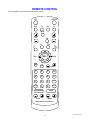
REMOTE CONTROL
Your Preamplifier Tuner includes an IR remote control.
OFF
DVD
POWER
TV
SAT
V2
MUTE
VOL
PRE
ON
TAPE
TU
CD
V1
SEL
BAL L
NE
R
BAL R
AM
FM
TUNE
1
2
3
BAND
4
5
6
ST/M
7
8
9
MENU
+10
0
E
MODE
A
LOUDNESS
SAVE
BASS
TREBLE
B&K REMOTE CONTROLLER
6
P/N 13010 REV 0005
MAKING THE CONNECTION
It’s tempting to just plug in your new Preamplifier Tuner and have great sound pour out. Before you do that, take a
few minutes to plan out how you want the Preamplifier Tuner to fit into your audio system. Ask yourself the
following questions:
y
What source components do I want to connect to my Preamplifier Tuner? (CD, DVD, etc.)
y
What equipment will be receiving the audio? (Amplifier, Powered Speakers, etc.)
The answers to your questions determine how many cables you need to connect to the back of the Preamplifier
Tuner. Good preplanning equals great sound. Keep these recommendations in mind:
y
List all components in your system and indicate which jacks of the Preamplifier Tuner each component will be
connected to. Your Preamplifier Tuner has six sets of inputs. It is convenient to connect a DVD player to the
input labeled DVD or a VCR to the input labeled V1 or TAPE, etc. However, your equipment may differ from
the labeling on the back of your Preamplifier Tuner. In most cases you can connect any type of source to any
input (see FREQUENTLY ASKED QUESTIONS). For example, if you have a satellite receiver you can
connect it to V2. You can also reprogram the source name that will appear on your Preamplifier Tuner’s front
panel. (See SETUP - SOURCE NAMES)
y
Also note the length of the cable for each component’s connection and describe how it should be routed or
draw your routing scheme below your list. You may want to label each cable with a name or number at both
ends. Use high quality connections to maintain high quality audio.
y
Think about the type and length of cable you need and obstacles in the cable’s path (doorways, furniture,
walkways, etc.). To decide which ones are right for you talk to your dealer about the various cable products
that are available.
y
For safety, keep all cables out of high traffic areas (hallways or doorways) and away from equipment that
radiates power, including amplifiers, power cords, heaters, etc.
y
If you might expand your audio system later, keep these ideas in mind as you plan current cable runs.
y
To provide the best tuner reception, make sure the antenna is at least several feet away from the Preamplifier
Tuner and any other equipment that may produce high frequency interference such as Personal computers,
CD players, halogen lamps, etc.
Take a look at the back panel of the Preamplifier Tuner. You will notice that the RCA-type audio input and output
connectors are identified by colors, red for right channel and white for the left channel audio.
7
P/N 13010 REV 0005
AUDIO CONNECTIONS
Connecting your analog sources to your Preamplifier Tuner
Audio source - connecting a CD player to the Preamplifier Tuner’s analog inputs. Use the same instructions for
connecting to other audio sources such as a DVD, television, satellite receiver, cable box, etc. Attach one end of
the audio interconnect cable to the left audio output on the CD player, then attach the other end to the left (white)
CD audio input on the Preamplifier Tuner. Repeat for the right (red) audio connection.
LINE INPUTS
CD
Right audio input from
CD output
Left audio input from
CD output
TAPE or audio recorder - connect a cassette deck or other recorder to TAPE.
Attach one end of the audio interconnect cable to the left audio output on the TAPE recorder, then attach the other
end to the left (white) TAPE audio input on the Preamplifier Tuner. Repeat for the right (red) audio connection.
TAPE
OUTPUT
INPUT
Right audio output
to TAPE input
Right audio input
from TAPE output
Left audio output
to TAPE input
Left audio input
from TAPE output
Attach one end of the audio interconnect cable to the left audio input on the TAPE recorder, then attach the other
end to the left (white) TAPE audio output on the Preamplifier Tuner. Repeat for the right (red) audio connection.
8
P/N 13010 REV 0005
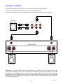
USING FULL RANGE SPEAKERS
Connect the Preamplifier Tuner’s outputs to your external amplifier(s) or powered speakers.
Shown below is a typical Preamplifier output setup for use with large speakers:
Note: the use of a sub woofer is optional.
POWERED
SUBWOOFER
PREAMP OUTPUTS
MONO
L+R
HIGH
PASS
FULL
RANGE
or
SUB
RIGHT INPUT
LEFT INPUT
Power Amplifier
RIGHT SPEAKER OUTPUT
MINUS
LEFT SPEAKER OUTPUT
MINUS
PLUS
PLUS
Front Right
Front Left
SUB output - Connect an RCA cable from the Preamplifier Tuner’s SUB output. If your subwoofer does not
contain its own amplifier you will need to purchase an external B&K or other power amplifier. Connect the
Preamplifier Tuner’s SUB output to the audio input of the external amplifier. Connect the external amplifier’s
speaker output to your subwoofer. If you prefer to use your subwoofer’s internal crossover, connect to the
Preamplifier Tuner’s Mono output.
9
P/N 13010 REV 0005
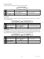
USING SMALL SPEAKERS
Connect the Preamplifier Tuner’s outputs to your external amplifier(s) or powered speakers.
Shown below is a typical Preamplifier output setup for use with small speakers:
Note: the use of a subwoofer is not optional and is needed to reproduce low frequency audio material.
POWERED
SUBWOOFER
PREAMP OUTPUTS
MONO
L+R
HIGH
PASS
FULL
RANGE
or
SUB
RIGHT INPUT
LEFT INPUT
Power Amplifier
RIGHT SPEAKER OUTPUT
MINUS
LEFT SPEAKER OUTPUT
MINUS
PLUS
PLUS
Front Right
Front Left
SUB output - Connect an RCA cable from the Preamplifier Tuner’s SUB output. If your subwoofer does not
contain its own amplifier you will need to purchase an external B&K or other power amplifier. Connect the
Preamplifier Tuner’s SUB output to the audio input of the external amplifier. Connect the external amplifier’s
speaker output to your subwoofer. If you prefer to use your subwoofer’s internal crossover then connect the
Preamplifier Tuner’s full range outputs to the sub’s input and connect your power amplifier or powered speaker’s
to the sub’s high-pass output.
10
P/N 13010 REV 0005
ANTENNA CONNECTIONS
The FM jack is a standard screw on F-type
connector. The AM is a push type. Strip ¼ inch
of insulation off your AM antenna wires and
insert one wire end into each hole while holding
the tabs down. Release the tabs to lock in the
AM antenna wires.
FM antenna
TUNER
FM Antenna Input
from Indoor/Outdoor Antenna,
Cable Box, etc.
AM antenna
AM Antenna Input
from Loop Antenna
CONTROL OUTPUT / IR INPUT
3.5 mm control output
to amplifier, etc.
ACCESSORY CONNECTION
CONTROL
OUT
CAUTION!
+12VDC
50mA
-
+
6 - 12VDC
38kHz
3.5 mm IR in
from remote repeater
Control Output - This connection is to be used for
controlling other equipment such as an external B&K
Components, Ltd. amplifier, projection screen, etc.
Connect your control cable to the Preamplifier Tuner using
a mono 3.5 mm jack shown at left. The plug must be
wired as tip (+) and the long barrel section (-).
IR INPUT
The Control output is programmable for each source in your system (see “Advanced Setup”). However, the
Preamplifier Tuner provides the following factory preprogrammed setup that should serve for most standard
system applications.
Control - HEADPHONE - On (+12 VDC) when the unit is on and not in Headphone mode, Off when the unit is off
or in Headphone Mode. This mode may be used for controlling external amplifiers or powered sub woofers in an
audio zone.
Note - The control outputs can output a maximum of 50 mA. Check to see that the source you are connecting to
the control out requires 50 mA or less current.
WARNING - Not all manufacturers adhere to the +12 VDC control specification. Check to see if your
sources control inputs are +12 VDC compatible. Do not connect your Preamplifier Tuner’s control outputs
to a source with control or remote inputs rated at +6 VDC or other voltage rating. Damage to your source
may result.
IR Inputs - Your Preamplifier Tuner can be controlled by a directly connected IR repeater system in combination
with or in place of the supplied remote control. Connect your IR input cable to the Preamplifier Tuner using a mono
3.5 mm jack shown above. The plug must be wired as tip (+) and the long barrel section (-). The input is standard
38 kHz modulated IR type with a voltage range of +6 to +12 VDC.
11
P/N 13010 REV 0005
OPERATION
The following outlines the normal day-to-day operation of your Preamplifier Tuner from the supplied IR remote
controller or directly from your Preamplifier Tuner’s front panel.
POWER ON/OFF
The main power switch on the front panel of your Preamplifier Tuner must be on for the Preamplifier Tuner to
operate. When this switch is off all power is removed from your Preamplifier Tuner. This prevents turning it back
on with the remote control. You can use the main power switch for normal day to day operation but we suggest
you use the sleep function instead so that the Preamplifier Tuner can be turned on and off from the remote. After
turning on the main power you must wait approximately 10 seconds while your Preamplifier Tuner restores its
internal memory and initializes various parameters. You may want to turn off the main power switch when your
Preamplifier Tuner will be idle for extended periods of time or during periods of power line fluctuations. Your
Preamplifier Tuner will not lose its memory while the main power switch is off.
3/($6( :$,7
From Remote
From Front Panel
Action
can’t turn off main power from remote
POWER ON/OFF
main power on/off
SLEEP
Normally you will simply put your Preamplifier Tuner to sleep (standby) when not in use. Sleep mode keeps a bare
minimum of functions running in order to allow remote control operation and fast start up. Note that the front panel
SLEEP button is lit while your Preamplifier Tuner is asleep and is off when your Preamplifier Tuner is operating.
The front panel alphanumeric display is off during sleep. Also note that the supplied IR remote’s POWER button is
a toggle to put your Preamplifier Tuner in and out of sleep. The remote control also has separate OFF and ON
buttons.
OFF
3/($6( :$,7
0$'( ,1 7+( 86$
37 35($03
From Remote
1 ON or POWER
2 OFF or POWER
From Front Panel
% . &20321(176
BK
9(56,21 Action
A SLEEP
A SLEEP
bring Preamplifier Tuner out of standby
put Preamplifier Tuner to sleep (standby)
ADJUSTING VOLUME
&'
92/80( From Remote
From Front Panel
Action
VOL - or VOL +
VOLUME KNOB
adjust volume
MUTE
can’t do from front panel
instant volume all the way down
press MUTE again to restore
Note: The front panel VOLUME control is also used to control multiple functions and, therefore, cannot always
control the LEVEL. The front panel display will indicate which LEVEL is currently being modified (VOLUME,
BALANCE, BASS, or TREBLE). The VOLUME KNOB never controls volume in the menu system. During normal
operation the VOLUME KNOB may switch to controlling other functions but will return to MASTER LEVEL after a
few seconds. The remote’s VOL − or VOL + will always change master volume level except in the SOURCE
LEVEL menus.
12
P/N 13010 REV 0005
CHOOSING A SOURCE
In general, the selected source will appear at the PREAMP outputs and the TAPE output.
&'
From Remote
desired source
'%
From Front Panel
Action
(SOURCE) step to source
select desired source
TAPE MONITOR - If you have an analog three-head cassette or reel-to-reel analog tape recorder you may wish to
use TAPE MONITOR, which allows you to hear exactly what is on the tape as you are recording.
7$3(
From Remote
From Front Panel
desired source
(SOURCE) step to source
TAPE
'%
Action
select desired source or TUNER
source will appear on TAPE output
(SOURCE) step quickly to TAPE
wait a few seconds while Preamplifier Tuner analyzes
selected source
select TAPE monitor
TAPE will appear at the preamp’s output
HEADPHONE MODE
Headphone Mode allows you to operate your Preamplifier Tuner with the CONTROL OUT set to off. This feature
allows your Preamplifier Tuner to turn off external amplifiers or powered sub woofers with compatible CONTROL
inputs. Your Preamplifier Tuner has the capability to be set up to allow for other control out functions (see
ADVANCED FEATURES).
+($'3+21( 2))
From Remote
1 MODE
+($'3+21( 21
From Front Panel
Action
Can’t do directly from front panel
refer to MENU operation
toggle headphone on/off
13
P/N 13010 REV 0005
ADJUSTING BALANCE
BAL (L) positions the source left by decreasing the right channel level. BAL (R) positions the source right by
decreasing the left channel level.
&'
&(17(5('
&'
to
5,*+7 From Remote
From Front Panel
Action
(BAL L) or(BAL R)
∠ (LEVEL) step to BALANCE
then use VOLUME KNOB
adjust balance left or right
ADJUSTING BASS
BASS +/- increase or decrease the low frequency content in 2 dB increments with a range of +/- 12 dB.
&'
%$66
From Remote
From Front Panel
Action
BASS - orBASS +
∠ (LEVEL) step to BASS
then use VOLUME KNOB
adjust bass up or down
ADJUSTING TREBLE
Treble +/- increase or decrease the high frequency content in 2 dB increments with a range of +/- 12 dB.
&'
75(%/( From Remote
From Front Panel
Action
TREBLE - orTREBLE +
∠ (LEVEL) step to TREBLE
then use VOLUME KNOB
adjust treble up or down
LOUDNESS
Loudness may be used to further shape the audio signal for increased clarity and intelligibility at low listening
levels.
&'
/28' 21
&'
or
From Remote
From Front Panel
Action
LOUDNESS
(LOUDNESS)
toggle on or off
14
/28' 2))
P/N 13010 REV 0005
TUNER OPERATION
All TUNER operations require the Preamplifier Tuner’s source be set to TUNER.
Manual Tuning - press TUNE + or TUNE - to tune the frequency UP or DOWN in single 10 kHz steps for AM or
200 kHz steps for FM. (9 kHz and 100 kHz steps for European version.)
Direct Frequency Entry Tuning - for a few seconds after performing any tuner operation (TUNER, BAND, AM, FM
or TUNE+/-) you may directly enter a frequency from the remote control’s numeric keypad.
Seek Tuning - Holding the remote TUNE +/- button will cause the tuner to SEEK (tune up or down automatically
stopping on strong stations). Once the tuner has started seeking you can let go of the button. Once a station is
found you must let go of the button before you can change frequencies again. In strong signal areas the tuner may
stop one step above or below the true frequency. Unless you are sure of the station’s frequency, check to see that
the signal might be better one step above or below the frequency that SEEK has found. In weak signal areas the
tuner may continue to seek all the way to the end of the band. To stop this simply press the opposite TUNE +/button.
)0
6((.
)0 67 )281'
to
BAND - toggles between the AM and FM frequency bands.
AM - selects and allows tuning of the AM frequency band.
FM - selects and allows tuning of the FM frequency band.
ST/M - allows selecting of Stereo and Mono in the FM frequency band. Setting/Programming a channel to Stereo
will play the channel in stereo if it is broadcast in stereo or in mono otherwise. Setting/Programming a channel to
Mono will force the channel to mono regardless of the broadcast. Use mono to reduce background noise on weak
channels.
)0 67(5(2
)0
From Remote
)0 0212
to
From Front Panel
Action
2 BAND or AM or FM
(SOURCE) step to source
(SOURCE) step to source
3 TUNE+ or TUNE-
∧ (UP) or ∨ (DOWN) and then
4 ST/M
Can’t do directly from front panel set FM stereo/mono
refer to MENU operation
1 TUNER
select TUNER
select AM or FM
manually tune up or down to desired frequency
see TUNER OPERATION for DIRECT / SEEK / TUNE
15
P/N 13010 REV 0005
PRESETS
Presets allow you to save your favorite settings and recall them instantly. Your Preamplifier Tuner can store forty
presets (0..39). Most Preamplifier Tuner’s only allow saving of tuner stations. With the presets you save not only
the tuner station but also the volume, bass, treble, balance, loudness, and headphone mode. This allows you, for
example, to save a music station with enhanced bass and a talk station with enhanced treble. You are not limited
to 20 AM stations and 20 FM stations. You can save 1 AM station and 39 FM stations, 1 FM and 39 AM or
anything in between. Also, presets are not limited to Tuner stations. You can save custom settings for any source.
A convenient set of 10 presets come preprogrammed with your Preamplifier Tuner.
Recalling a Preset
FG
From Remote
GE
5(&$//,1* 35(6(7
From Front Panel
Action
1 number or +10 + number
(PRESET) step to desired preset
review settings for recall
2 SEL or ENTER
↵ (ENTER)
recall preset
Saving a Preset
FG
From Remote
GE
6$9,1* 6(77,1*6
From Front Panel
Action
1 make all settings you wish to save make all settings you wish to save
2 SAVE
(SAVE)
prepare for saving preset
activate preset save
1 number or +10 + number
(PRESET) step to desired preset
Select preset number you
wish to replace
3 or
(BAL L) or(BAL R)
∧ (TUNE +) or ∨ (TUNE -)
VOLUME KNOB
rename preset if desired
4 SEL or ENTER
↵ (ENTER)
save preset
16
P/N 13010 REV 0005
MENU
For best results, perform the following set up procedure when you initially install your Preamplifier Tuner and
anytime you change or add sources, speakers, etc. or when you rearrange your listening area
THE MENU SYSTEM
Setup of your Preamplifier Tuner will require you to navigate through the menu system via the front panel or
remote. A complete guide to the menu system is included at the back of this manual. We recommend that you
become familiar with your Preamplifier Tuner’s menu guide. The following are general instructions for using the
menu system.
MENU - If you are not already in the menu system, the MENU button on the remote controller will activate the
menu system (or, simultaneously pressing PRESET and ENTER from the front panel). Once you are in the menu
system, the MENU button will return you to the next higher level menu or, if you are already at the highest level, it
will exit from the menu system.
UP/DOWN ARROWS - Once you are in the menu system, use the TUNE+ / TUNE- ARROWS to move to the
desired menu selection.
SELECT (remote) or ENTER (remote or front panel) - Some menu selections cause another menu to be
activated. Use the TUNE+ / TUNE- ARROWS to move to the desired menu line. Pressing SELECT or ENTER will
activate the next menu.
LEFT/RIGHT ARROWS (remote) or VOLUME KNOB (front panel) - Some menu selections allow you to change
one of the Preamplifier Tuner settings. Use the TUNE+ / TUNE- ARROWS to move to the desired menu line.
Pressing the LEFT/RIGHT ARROWS will change the setting. There are no LEFT/RIGHT ARROWS on the front
panel. While in the menu system, the VOLUME KNOB acts as the LEFT/RIGHT ARROWS. This means that you
will not be able to adjust the volume from the front panel while in the menu system. The remote control volume will
work in most menus.
TEXT EDITING - Some menu selections will require you to edit text. Use the TUNE+ / TUNE- ARROWS to
change the current (blinking) character. Use the LEFT/RIGHT ARROWS (or VOLUME KNOB) to move to another
character position.
17
P/N 13010 REV 0005
HEADPHONE ON
The MAIN MENU Headphone selection provides for operating your Preamplifier Tuner’s with the CONTROL OUT
set to off. This feature allows your Preamplifier Tuner to turn off external amplifiers or powered sub woofers with
compatible CONTROL inputs. Your Preamplifier Tuner has the capability to be set up to allow for other control out
functions (see ADVANCED FEATURES).
+($'3+21( 2))
From Remote
1 MENU
2
(BAL L) or(BAL R)
3 MENU
+($'3+21( 21
From Front Panel
Action
(PRESET) and ↵ (ENTER)
select headphone mode
VOLUME KNOB
Turn headphone mode on/off
(PRESET) and ↵ (ENTER)
exit from menu system
HELP
The HELP GUIDE summarizes the basic menu operations described herein. The guide will automatically scroll
through each line.
+(/3
From Remote
From Front Panel
Action
1 MENU
(PRESET) and ↵ (ENTER)
enter menu system
2 or to HELP
∧ (TUNE +) or ∨ (TUNE -) to HELP
move to help
3 SEL or ENTER
↵ ( ENTER)
display help guide
4 MENU
(PRESET) and ↵ (ENTER)
return to main menu
5 MENU
(PRESET) and ↵ (ENTER)
exit menu system
PRODUCT INFO
The PRODUCT INFORMATION selection that provides basic information on your Preamplifier Tuner. The
information will automatically scroll through each line.
352'8&7 ,1)2
From Remote
From Front Panel
Action
1 MENU
(PRESET) and ↵ (ENTER)
enter menu system
2 or to HELP
∧ (TUNE +) or ∨ (TUNE -) to HELP
move to product info
3 SEL or ENTER
↵ ( ENTER)
display product info
4 MENU
(PRESET) and ↵ (ENTER)
return to main menu
5 MENU
(PRESET) and ↵ (ENTER)
exit menu system
18
P/N 13010 REV 0005
SETUP
The MAIN MENU provides a SETUP selection that enables more advanced customization of your Preamplifier
Tuner's operation.
6(783
From Remote
From Front Panel
Action
1 MENU
(PRESET) and ↵ (ENTER)
enter menu system
2 or
∧ (TUNE +) or ∨ (TUNE -)
move to setup
3 SEL or ENTER
↵ ( ENTER)
enter setup menu
Favorite Preset Setup
Favorite presets need only be setup after adding/changing presets or sources. This feature allows for skipping
selected presets when pressing the remote Preset +/- buttons or front panel preset (+) button. When you save a
preset it will be automatically added to the favorite preset list.
)$925,7( 35(6(76
From Remote
'9'
<(6
From Front Panel
Action
1 From setup menu:
or
From setup menu:
∧ (TUNE +) or ∨ (TUNE -)
move to favorite presets
2 SEL or ENTER
↵ ( ENTER)
enter favorite preset menu
3 or
∧ (TUNE +) or ∨ (TUNE -)
move to desired preset
VOLUME KNOB
select no (skip) or yes
5 repeat 3-4
repeat 3-4
program additional presets
6 MENU
(PRESET) and ↵ (ENTER)
return to setup menu
4
(BAL L) or(BAL R)
19
P/N 13010 REV 0005
Source Names Setup
From the factory, your Preamplifier Tuner will display source names that match those printed on the rear of the
Preamplifier Tuner and on the supplied remote. However, this menu allows you to change the displayed names to
match the actual sources used. If you do not want to change the names then skip this step. Note that the tuner
name cannot be changed.
6285&( 1$0(6
From Remote
9
9&5
From Front Panel
Action
1 From setup menu:
or
From setup menu:
∧ (TUNE +) or ∨ (TUNE -)
move to source names
2 SEL or ENTER
↵ ( ENTER)
enter source names menu
3 desired source
(SOURCE) step to source
select desired source for renaming
4 or
∧ (TUNE +) or ∨ (TUNE -)
change blinking character
VOLUME KNOB
move to new character position
6 repeat 4-5
repeat 4-5
until all renaming complete
7 repeat 3-6
repeat 3-6
to rename additional sources
8 MENU
(PRESET) and ↵ (ENTER)
return to setup menu
5
(BAL L) or(BAL R)
Source Levels Setup
This setup allows you to match the levels of your sources so that there are no large changes in volume as you
change from one source to another. This is for your convenience only and need not be performed unless you wish
to. You may use a SPL meter or your ear to adjust the levels. Note that the levels will depend not only on this
setting but also on the source material being played back. You may wish to use a test disc. Note that the only
setting permitted are 0 and -6dB.
6285&( /(9(/6
From Remote
9
9&5
GE
From Front Panel
Action
1 From setup menu:
or
From setup menu:
∧ (TUNE +) or ∨ (TUNE -)
move to source levels
2 SEL or ENTER
↵ ( ENTER)
enter source levels menu
(SOURCE) step to source
select desired source for level setup
VOLUME KNOB
set desired level
5 repeat 3-4
repeat 3-4
set additional source levels
6 MENU
(PRESET) and ↵ (ENTER)
return to setup menu
3 desired source
4
(BAL L) or(BAL R)
20
P/N 13010 REV 0005
Preset Operation Setup
This menu allows you to configure various aspects of how presets function.
35(6(7 23(5$7,21
From Remote
From Front Panel
Action
1 From setup menu:
or
From setup menu:
∧ (TUNE +) or ∨ (TUNE -)
move to preset operation
2 SEL or ENTER
↵ ( ENTER)
enter preset operation menu
Preset Volume
You can program presets to recall the volume level setting in effect when you saved the preset or to always use
the current volume Setting.
35(6(7 23(5$7,21
From Remote
&855(17 92/80(
From Front Panel
Action
1 From preset operation menu: From preset operation menu:
or
∧ (TUNE +) or ∨ (TUNE -)
2
(BAL L) or(BAL R)
VOLUME KNOB
move to current or preset volume
Select current or preset
Preset Naming
Your Preamplifier Tuner can automatically generate a preset name when saving presets based on the selected
source. Alternatively, you can program it to retain the current preset name when saving presets. In either case you
can still edit the (current or automatically generated) name before confirming the preset save.
35(6(7 23(5$7,21
From Remote
$872 1$0,1* <(6
From Front Panel
Action
1 From preset operation menu: From preset operation menu:
or
∧ (TUNE +) or ∨ (TUNE -)
2
(BAL L) or(BAL R)
3 MENU
move to auto naming
VOLUME KNOB
select auto naming yes or no
(PRESET) and ↵ (ENTER)
return to setup menu
21
P/N 13010 REV 0005
Display Setup
Set the intensity of the front panel’s alphanumeric display.
',63/$< 6(783
From Remote
',63/$< %5,*+7
From Front Panel
Action
1 From setup menu:
or
From setup menu:
∧ (TUNE +) or ∨ (TUNE -)
move to display setup
2 SEL or ENTER
↵ ( ENTER)
enter display setup menu
VOLUME KNOB
set display bright, medium, or dim
(PRESET) and ↵ (ENTER)
return to setup menu
3
(BAL L) or(BAL R)
4 MENU
Memory Options
Your Preamplifier Tuner continually saves any settings you have made even if power is lost. However, you may
wish to save a backup of your settings in case of inadvertent changes to them.
0(025< 237,216
From Remote
%$&.83 0(025<
6(/ 72 &21),50
From Front Panel
Action
1 From setup menu:
or
From setup menu:
∧ (TUNE +) or ∨ (TUNE -)
move to memory options
2 SEL or ENTER
↵ ( ENTER)
enter memory options menu
VOLUME KNOB
select backup or restore memory
4 SEL or ENTER
↵ ( ENTER)
activate selected memory operation
5 SEL or ENTER
↵ ( ENTER)
confirm selected memory operation
note: this takes a few seconds
6 MENU
(PRESET) and ↵ (ENTER)
return to setup menu
7 MENU
(PRESET) and ↵ (ENTER)
return to main menu
8 MENU
(PRESET) and ↵ (ENTER)
return to normal operation
3
(BAL L) or(BAL R)
To restore backup settings perform the same procedure as described above but select restore instead of backup.
If you have never made a backup, then performing a restore will call back the original factory settings.
22
P/N 13010 REV 0005
FREQUENTLY ASKED QUESTIONS
My collection of equipment differs from the labels on the back of my Preamplifier Tuner, how can I hook
them up?
Your Preamplifier Tuner provides 5 identical sets of inputs - V1, V2, TV, DVD and CD. It is convenient to
connect components as labeled on the back of your Preamplifier Tuner, but since all the inputs are identical, you
can connect any compatible source to any set of inputs. For example, you can connect a DAT player to V1 instead
of a VCR. You can program your Preamplifier Tuner to display any 5 character name for any input (see SETUP SOURCE NAMES).
The sixth input, TAPE, is primarily intended for analog recorders such as a cassette deck, DAT or Mini
Disc. If you have a three-head cassette or reel-to-reel tape deck you will prefer the TAPE input since it allows a full
tape monitor capability. Tape monitor allows you to listen to what is actually on the tape as you are recording it.
The Loudness control does not work at high volume settings. Is this normal?
Your Preamplifier Tuner’s Loudness control is designed to automatically shape the audio signal for
increased clarity and intelligibility during LOW VOLUME settings (below -15 dB). The control circuit is designed to
gradually reduce its effect on the audio signal as the volume is increased. Loudness is completely removed as the
level approaches 0 dB.
Can I connect a phonograph directly to my Preamplifier Tuner?
No, you will need a separate outboard phono preamplifier. The output of the phone preamp can then be
connected to any analog input on your Preamplifier Tuner. There are several high-quality outboard phono preamps
available such as the B&K Phono 10. Talk to the dealer where you purchased your Preamplifier Tuner.
23
P/N 13010 REV 0005
ADVANCED SETUP FEATURES
WARNING -
The following describes the advanced features of the Preamplifier Tuner. Since changing
some of these functions may cause severe effects such as no sound or no remote control operation, we suggest
you leave this menu disabled (hidden) for normal operation. If you are unsure of what you are changing DO NOT
perform any advanced operations. These features may be activated by simultaneously pressing the SLEEP,
DOWN, and UP buttons on the front panel of the Preamplifier Tuner. It will be assumed the user of these
advanced features is already familiar with how to navigate and adjust parameters in the Preamplifier Tuner's
MENU system. An Advanced Setup Flow Chart has been supplied at the end of this manual as a visual aid for the
menu’s navigation.
Note - if you have enabled the Advanced Visible option then you can return to this menu to hide the advanced
visible selection by simultaneously pressing the SLEEP, TUNE-, and TUNE+ buttons and selecting Hidden.
MISCELLANEOUS SETUP
Configuration will allow you to set a maximum volume level and change remote control ID codes for use in a
multi-zone application.
Max Level - max level allows you to set a maximum volume level. This is very useful if you are using speakers or
amplifiers that can’t handle the output level from your Preamplifier Tuner or if you simply wish to limit the volume
that can be achieved using normal front panel or remote operation.
Max Level may be set from -74 dB to + 8 dB (default).
WARNING - If you set this level too low, the Preamplifier Tuner may appear broken (no sound).
Product ID - Each transmitted IR message from your remote control includes a Product ID code that is used to
distinguish it from other devices. Product ID codes allow multiple B&K products to be controlled from the same IR
remote control. From the factory, your Preamplifier Tuner is to use Product ID code 2. There are 16 valid Product
ID’s available for this product. Make sure you are in the ADVANCED SETTINGS menu.
WARNING - If you change the product ID code in the Preamplifier Tuner without having the capability to
generate this new IR code, your Preamplifier Tuner will no longer have IR control capability. If this feature
is to be implemented, we recommend our AV5.1 or AV7.1 preprogrammed & learning remote control. The
AV5.1 / AV7.1 has the capability to generate messages using these 16 product ID codes.
POWER ON TITLES
When you turn your Preamplifier Tuner on it displays three lines of text on the front panel’s alphanumeric display.
You can change two of these lines of text to a personalized message.
% . &20321(176
to
+$52/'6 $8',2
0$'( ,1 7+( 86$
to
*5($7 6281'
24
P/N 13010 REV 0005
CONTROL OUT SETUP
Your Preamplifier Tuner’s control output allows you to control external devices such as power amplifiers,
projection screens, etc. The control output can be programmed on/off depending on which source is selected.
Control Out - Control out can be programmed to be on or off for each source. For example you may wish to use
the control out to turn on an external video projector whenever DVD is selected. Control out can also be set to
HEADPHONE mode. HEADPHONE mode is intended to control external amplifiers to permit headphone listening
without the need for manually turning off your external amplifiers. It is recommended that if HEADPHONE is set for
one source then it should be set to HEADPHONE for all sources. Control out can also be set to REMOTE. In
REMOTE mode your Preamplifier Tuner acts like a remote repeater - IR remote signals detected by your
Preamplifier Tuner are repeated on the control out. It is recommended that if REMOTE is set for one source then it
should be set to REMOTE for all sources.
The Control Out available settings are PHONES (Default), REMOTE, OFF, ON.
SECURITY OPTIONS
Security options allow you to hide the ADVANCED SETUP menu to prevent inadvertent changes to advanced
system settings. This menu also allows you to lock various features available in your Preamplifier Tuner.
Advanced Visible - Options are VISIBLE and HIDDEN (default).
Memory Lock - Options are YES and NO (default). Locking memory will prevent changes to presets and system
setup settings. Note: Locking Memory will also remove SETUP as a selection from the Preamplifier Tuner’s
MENU. SLEEP, TUNE-, and TUNE+ buttons pressed simultaneously will always allow access to Advanced
Setup editing.
Front Lock - Options are YES and NO (default). Locking the front panel will prevent changing or adjusting the
Preamplifier Tuner using the front panel buttons. This feature is most useful in custom applications were it is
advantageous to disable user control with the front panel. Note: SLEEP, TUNE-, and TUNE+ buttons pressed
simultaneously will always disable the Front Panel Lock feature and allow for continued editing of the
Advanced Setup features.
IR Lock - Options are YES and NO (default). Locking out IR control will prevent changing or adjusting the
Preamplifier Tuner using ANY IR remote control. This feature is most useful in custom applications were it is
advantageous to disable user control with an IR controller. Note: SLEEP, TUNE-, and TUNE+ buttons pressed
simultaneously will always disable the IR Lock feature and allow for continued editing of the Advanced
Setup features.
After completing all of your advanced settings you may wish to backup the settings (not available if MEMORY
LOCK is set to YES). Refer to Memory Backup in the Setup section of this manual.
FACTORY RESET
Should you ever need to completely reset the Preamplifier Tuner to the original factory settings, by pressing the
front panel SLEEP, DOWN, and LEVEL buttons simultaneously. The Preamplifier Tuner will perform a
complete reset and erase all user programmed presets, menu settings, and any previously made memory
backup.
25
P/N 13010 REV 0005
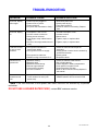
TROUBLESHOOTING
PROBLEM
POSSIBLE CAUSE
POSSIBLE SOLUTION
No sound, display
will not light
1. Power cord not plugged in.
2. Power off at AC source.
3. Power switch off.
4. AC power inlet fuse blown or faulty.*
1. Reconnect power cord.
2. Check power at plug.
3. Turn power switch on.
4. Check for shorts or overloading. Replace
fuse.
No sound, display
on.
1. Preamplifier Tuner in mute
2. Volume control to minimum.
3. Wrong source selected.
4. Line stage to amp. cables loose or
faulty.
5. Source to line stage cables loose or
faulty.
1. Unmute Preamplifier Tuner.
2. Increase volume.
3. Select source.
4. Tighten, repair, or replace cable.
1. Poor ground connection in
interconnect cables.
2. Poor ground in main AC supply.
1. Check all connectors and repair as
necessary.
2. Check ground of outlet. Have it checked by
qualified serviceman.
3. Check ground.
4. Reposition cables.
Loud hum or buzz
on one or more
channels
3. Poor ground on cable box.
4. Cables running across back of TV.
5. Tighten, repair, or replace cable.
Remote will not
operate unit.
1. Batteries missing.
2. Batteries dead.
3. Batteries inserted wrong.
4. Remote signal blocked.
5. Lens requires cleaning.
6. IR Lock is enabled
1. Check for batteries inside remote.
2. Put in fresh batteries.
3. Follow diagram in battery compartment.
4. Clear path to front panel of unit.
5. Clean lens with a soft cloth.
6. Refer to IR Lock under Security Options in
this manual
One or more
channels sound
bad
1. It is possible that the Preamplifier
Tuner needs to be reset (cold
power boot).
1. Cycle the Preamplifier Tuner’s front panel
POWER switch to OFF then back to ON.
* Note: If the unit continues to blow power inlet fuses, have the unit checked by a qualified
technician.
DO NOT USE A HIGHER RATED FUSE!, contact B&K customer service.
26
P/N 13010 REV 0005
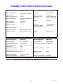
PREAMPLIFIER TUNER SPECIFICATIONS
Miscellaneous
Preamplifier Specifications
Frequency Response:
5 Hz - 20 kHz , +0/0.5dB
Line voltage:
120/220/240 VAC
Input Sensitivity:
63 mV
Power consumption:
30 watts max
Maximum Output Level:
8 V rms
Replacement fuses:
Line 0.5 Amp/250 Volt
Signal to Noise Ratio:
89 dB CCIR 2 k Weighted
max level
Dimensions:
17"(w)x10"(d)x3.50"(h)
Input Impedance:
50 k Ohms
Weight:
10 pounds
Output Impedance:
221 Ohms
Audio Analog Inputs
6
Warranty:
See Warranty page for
complete explanation
5 years preamplifier
1 year remote
Audio Analog Outputs
4
High Pass Crossover
80 Hz 12 dB per octave
Low Pass Crossover
80 Hz 12 dB per octave
Upgrade:
RS232 software
Tuner Specifications
FM Section
Tuner Specifications
AM section
Frequency Range:
87.5 - 107.9 MHz
Frequency Range:
520 - 1670 kHz
Total Harmonic Distortion:
Less than 0.25%
Total Harmonic Distortion: Less than 0.3%
Frequency Response
20 Hz - 15 kHz, +1/ -3 dB
Capture Ratio:
2 dB
IHF (Usable) Sensitivity:
12 dBf
Mono/Stereo Sensitivity:
15 / 35 dBf
Alternate Channel Selectivity: 65 dB
Signal to Noise Ratio:
70 dB, A Weighted
Antenna Input Impedance:
75 Ohms
IHF (Usable) Sensitivity:
28 dBf
Alternate Channel
Selectivity:
30 dB
Antenna Input Impedance: 300 Ohms
Specifications subject to change without notice
27
P/N 13010 REV 0005
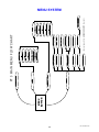
=5>E
2EDD?>
28
6(783
352'8&7 ,1)2
+(/3
+($'3+21( 21
799 <(6
'9'
'%
'9'
6(/ 72 &21),50
0$'( ,1 7+( 86$
3(5621$/ 35(6(76
86(5 &21752/6
(See next page for the ADVANCED SETUP flow chart)
%$&.83 0(025<
0(025< 237,216
$'9$1&(' 6(783
',63/$< %5,*+7
$872 1$0,1* <(6
35(6(7 92/80(
'9'
'9'
',63/$< 6(783
35(6(7 23(5$7,21
6285&( /(9(/6
6285&( 1$0(6
)$925,7( 35(6(76
781(5 35($03
0(18 72 (;,7
352*5$00$%/(
%. 37
(17(5 72 6(/(&7
6(/ 72 6(/(&7
92/ '(&,1&
83'1 52:7;7
0(18 21 %$&.
PT 3 MAIN MENU FLOW CHART
MENU SYSTEM
P/N 13010 REV 0005
$'9$1&(' 6(783
29
(option)
56 3257
6(&85,7< 237,216
&21752/ 6(783
32:(5 21 7,7/(6
0,6&(//$1(286
75$160,7 ,' 5(&(,9( ,' 83'$7( (1$%/('
(&+2 (1$%/('
%$8' 5$7( 3257 (1$%/('
,5 /2&. 12
)5217 /2&. 12
0(025< /2&. 12
$'9$1&(' 9,6,%/(
32:(5 21 /,1( 32:(5 21 /,1( 352'8&7 ,' 0$; /(9(/ '%
& 7$3( 3+21(6
3+21(6
3+21(6
& '9'
& &'
3+21(6
3+21(6
& 9
& 79
3+21(6
& 9
& 781(5 3+21(6
ADAVNCED SETUP FLOW CHART
ADVANCED MENU SYSTEM
P/N 13010 REV 0005
CAUTION
B&K Components, Ltd.
2100 Old Union Rd.
Buffalo, NY 14227
www.bkcomp.com
COMPLIES WITH THE LIMITS
FOR A CLASS B COMPUTING
DEVICE PURSUANT TO
SUBPART J OF PART 15
RISK OF ELECTRIC SHOCK
DO NOT OPEN
SERIAL NUMBER
AC IN
www.bkcomp.com
RS-232
30
IR INPUT
6-12VDC
38kHz
12VDC
50mA
CONTROL
OUT
ACCESSORY CONNECTION
SUB
PREAMP OUTPUTS
MONO
HIGH
FULL
L+R
PASS
RANGE
OUTPUT
INPUT
TAPE
CD
DVD
TV
SOURCE INPUTS
Audio/Video Systems made in the U.S.A.
V2
V1
AM antenna
TUNER
FM antenna
REAR PANEL ENLARGED VIEW
P/N 13010 REV 0005
NOTES
31
P/N 13010 REV 0005
LIMITED WARRANTY
B&K Components Ltd., referred to herein as B&K, warrants your B&K equipment against all defects in material
and workmanship for a period of five years from the date of purchase. This warranty applies only to the original
purchaser and only to equipment in normal residential use and service. Defective equipment must be returned to
B&K, prepaid, accompanied by sufficient payment to cover the cost of return shipping and handling, and will be
repaired or replaced at the discretion of B&K whose decision as to the method of reparation will be final.
This warranty shall not apply to any equipment which is found to have been improperly installed, incorrectly fused,
misused, abused, or subjected to harmful elements, used in any way not in accordance with instructions supplied
with the unit, or to have been modified, repaired or altered in any way without the expressed, written consent of
B&K. This warranty does not apply to the cabinet, the remote controller, or appearance items such as the face
plate, control buttons, or display lenses, nor does it cover any expenses incurred in shipping the unit to and from
the manufacturer’s service depot.
No warranty, implied or otherwise created by State law shall extend beyond the terms of this warranty and B&K
shall not be liable for any incidental or consequential damage arising out of a defect in material or workmanship of
the unit during the terms of this warranty or thereafter. Some States do not allow the exclusion or limitation of
incidental or consequential damages and the foregoing exclusions may not apply to you.
This warranty gives you specific legal rights. You may also have other rights that vary from State to State.
No agent, representative, dealer or employee of B&K has the authority to increase or alter the obligations or terms
of this warranty.
B&K Components Ltd.
Warranty on the Remote Control is 1 year parts and labor. Customer is responsible for
shipping to and from the factory
RETURNING EQUIPMENT
No equipment may be returned to B&K Components Ltd. without a RETURN AUTHORIZATION. Should you find it
necessary to return equipment to B&K, for any reason, a RETURN AUTHORIZATION (RA) number must be
issued by B&K with respect to the equipment being returned. You may request an RA number by calling B&K at
one of the below listed telephone numbers.
Customer Service
Information
800-543-4242
716-656-0026.
We will need the following information to issue your RA number. Before you call please have the following.
1.
2.
3.
4.
Your name, address, and phone number.
The model and serial number of the equipment to be returned.
A description of the problem.
Your sales receipt.
Your call will be referred to a Technical Service Representative who will work with you to resolve the problem. If it
is determined that the unit must be returned for repair, an RA number will be issued and the unit should be
shipped to:
B&K Components Ltd.
2100 Old Union Road.
Buffalo, New York 14227
32
P/N 13010 REV 0005
33
P/N 13010 REV 0005