1
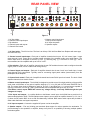
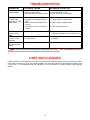
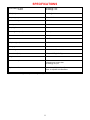
B&K
SIMPLY BETTER!
B&K Components, Ltd.
AV2600
Owner’s Manual
P/N12930 0802
B&K Components, Ltd., 2100 Old Union Road, Buffalo New York 14227-2725
Phone 1-800-543-5252 or (716) 656-0026, Fax (716) 656-1291
E-mail: [email protected] Web: www.bkcomp.com
ii
TABLE OF CONTENTS
Table of Contents...................................................................................................................................iii
Safety Precautions .................................................................................................................................1
Purpose and Function ............................................................................................................................2
Features ...................................................................................................................................................2
Rear Panel View ......................................................................................................................................3
DIP Switch Setting ..................................................................................................................................4
Channel Control & Muting......................................................................................................................5
Master Control & Muting ........................................................................................................................5
Level Control ...........................................................................................................................................5
Input Connections ..................................................................................................................................6
Output Connections ...............................................................................................................................6
Level Control Defeat ...............................................................................................................................7
Jumper Settings......................................................................................................................................7
High Current (Mono) Usage ...................................................................................................................8
System Installation .................................................................................................................................9
Making the Connection ..........................................................................................................................9
Troubleshooting....................................................................................................................................10
Care and Cleaning ................................................................................................................................10
Specifications .......................................................................................................................................11
Limited Warranty..................................................................................................................................................................12
Returning Equipment ............................................................................................................................................................12
WWW.BKCOMP.COM ...........................................................................................................................13
iii
SAFETY PRECAUTIONS
PLEASE READ BEFORE INSTALLING
WARNING: to prevent fire or shock hazard, do not expose this unit to rain or moisture. Care should be
taken to prevent objects or liquid from entering the enclosure. Never handle the power cord with wet
hands.
•
The lightning flash with arrowhead, within an equilateral triangle, is intended to alert the user of the
presence of uninsulated “dangerous voltage” within the product’s enclosure that may constitute a risk of
electric shock to you.
•
The exclamation point within an equilateral triangle is intended to alert the user of the presence of
important operating and maintenance (servicing) instructions in the literature accompanying the unit.
•
Caution: To prevent the risk of electric shock, do not remove cover. No user-serviceable parts inside.
Refer servicing to qualified service personnel.
•
Unplug the amplifier from the AC outlet when plugging in or unplugging cables, when left unused for an
extended period of time, moving the amplifier, or when you suspect lightning in your area.
•
Prevent damage to the power cord. Do not bend, pull, place objects on, alter, etc. Replace the power cord
if it becomes damaged. Always grasp the plug on the power cord when plugging in or unplugging the
amplifier from the AC outlet.
•
Your system may produce sound levels capable of causing permanent hearing loss. Do not operate for
extended periods of time at high volume levels.
•
Make sure the amplifier is placed on a level surface.
•
The amplifier is equipped with raised feet to provide ventilation, reduce acoustic feedback, and provide
protection against scratching the surface the unit is resting on. We advise against removing or altering
feet.
•
Do not stack anything on top of the amplifier (processor, source, etc.) Leave a minimum of 2” clearance
from the top of the amplifier to the next shelf (or component) to insure proper ventilation.
•
The amplifier should be located away from other sources that may be sensitive to heat.
•
Do not perform any internal modifications to the amplifier.
•
Always connect the amplifier’s power cord to an unswitched AC outlet for normal operation.
•
If young children are present, adult supervision should be provided until the children are capable of
following all rules for safe operation.
•
Do not plug the amplifier’s power cord into an outlet with an unreasonable number of other devices. Be
careful if using extension cords and ensure the total power used by all devices does not exceed the
power rating (watts/amperes) of the extension cord. Excessive loads may cause the insulation on the
cord to heat and possibly melt.
•
Mistaking CONTROL OUTPUT or CONTROL INPUT connectors for audio/video inputs or outputs may
damage your amplifier or other components.
•
Damage can occur to your speakers if the power rating of each individual driver is exceeded by the
amplifier. Ensure that all the drivers in your system are capable of handling not only the average power
being delivered by the amplifiers, but also the peak power that is likely to be generated during strong
passages. If you are unsure of your speaker's power rating, contact the speaker manufacturer or the
dealer where you purchased them.
•
The amplifier should be serviced by qualified personnel when:
A. The amplifier is not functioning properly.
B. Objects have entered the chassis.
C. The amplifier was exposed to rain or other type of moisture.
D. The amplifier was dropped, or the chassis is damaged.
1
PURPOSE AND FUNCTION
The AV2600 is an integration of a stereo audio distribution BUS with six compact and efficient 60 W power
amplifiers. Each pair of amplifiers have DIP switches that allow system configuration for use with either
mono/stereo and muting control via a Master or Local control input. Additionally, there is support for paralleling
multiple speaker output channels to allow greater output current capability. It is clear the AV2600 is designed to
allow flexibility and functionality in the design of Multi Zone power system applications. The term versatile is
almost inadequate to describe the multitude of operational modes the AV2600 is capable of providing.
Below are just a few of the tasks the AV2600 may be configured to perform:
• The most obvious example allows for three stereo audio input pairs to power three pairs of
amplified speaker outputs. This is the default factory configuration.
• Using the audio distribution BUS, DIP switches allow independent configuration for up to 3 pairs of
mono or stereo, with independent automatic audio sense muting per amplifier output pair.
• The availability of both Local and BUS audio outputs, allows for a number of units to be cascaded
for easy and efficient system expansion.
FEATURES
Toroidal Transformer - Efficient high current power delivery for improved dynamics.
Computer Grade Capacitors - Large capacity computer grade electrolytic capacitors for high transient power
delivery and extended low frequency control.
Limited Protection - Increased Safe Operating Area and thermal overload allows for continuous duty unattended
use.
Gold Plated Connectors - Improved connections for better sound and minimized signal loss and degradation.
1% Metal Film Resistors - Low noise precision resistors offer a cleaner more repeatable sound quality.
High Current Circuitry - More accurate and three dimensional reproduction of source material with sonic fidelity
usually found only in larger power amplifiers.
2
REAR PANEL VIEW
2
1
SERIAL
NUMBER
CTRL 5/6
OUT
OUT
5
IN
IN
OUT
6
IN
LEVEL
5/6
BUS
L+R
SENSE
AMP ON
3
CTRL 3/4
OUT
OUT
3
IN
IN
OUT
4
IN
LEVEL
3/4
BUS
L+R
SENSE
AMP ON
4
CTRL 1/2
OUT
OUT
1
IN
IN
OUT
2
IN
5
6
LEVEL
1/2
BUS
L+R
SENSE
AMP ON
7
MASTER
CONTROL
OUT
IN
BUS
OUT
IN
IN
OUT
FUSE
CAUTION: FOR CONTINUED
PROTECTION AGAINST RISK
O F F I R E R E P L A C E O N LY
W I T H S A M E T Y P E 1 5 A 2 5 0 V.
ON
MIN
OUT 6
MAX
ON
MIN
1 2 3 4
OUT 5
MAX
OUT 4
1
ON
MIN
2 3 4
OUT 3
MAX
1 2 3 4
OUT 2
OUT 1
A.C.LINE
VOLTAGE
MINUS
PLUS
MINUS
PLUS
MINUS
PLUS
8
MINUS
PLUS
MINUS
PLUS
MINUS
PLUS
9
Figure 1
1. AC fuse holder
2. Channel control input/output
3. Dip switches
4. Channel inputs and outputs
5. Channel level control
6. Master control input/output
7. Bus inputs and outputs
8. AC input receptacle
9. Speaker outputs
1. AC fuse holder - The AC Line fuse. The fuse is an 8 Amp / 250 Volt Slow Blow fuse. Replace with same type
and value fuse only.
2. Channel control input/output - Each pair of amplifier channels has its own 1/8” mini control input / output
(pass through) ‘Local’ control jack to provide remote switching of the amplifier audio mute on/off feature. The
control input circuit is designed to work as Tip Pos. (+) and Ring Neg. (-). A minimum of 5VDC @ 1 mA is
recommended, and is compatible with up to 24V AC or DC.
3. Dip switches - Each pair of amplifier channels has its own DIP switches that are used to configure the audio
signal (‘Local’ or ‘BUS’, mono or stereo and muting control).
4. Channel inputs and outputs - Each pair of amplifier channels has its own ‘Local’ set of audio input / output
(pass through) RCA connections. Typically used for connecting signal patch cables (interconnects) from the
preamplifier to the amplifier.
5. Channel level control - Each pair of amplifier channels has its own DUAL input level control. The level of both
amplifier channels is set via this control.
6. Master control input/output - The AV2600 is designed to provide control for single switching of the amplifier
audio mute on/off feature on any pair of amplifier channels (1-2, 3-4 or 5-6) with it’s DIP switch ‘MASTER’ set to
ON. The control input circuit is designed to work as Tip Pos. (+) and Ring Neg. (-). A control source capable of
sourcing a minimum of 5 VDC @ 1 mA is recommended, and is compatible with up to 24V AC or DC.
(The Master control output DOES NOT source any voltage directly, it will only PASS through the input
voltage at it’s input).
7. Bus inputs and outputs - In a similar fashion to the Master control input, the AV2600 has a provision for a
stereo audio distribution ‘BUS’. This BUS allows stereo inputs to source audio to amplifier channels (1-2, 3-4 or 56) when the DIP switch ‘BUS’ is set to ON. Simultaneously, buffered ‘BUS’ stereo audio outputs are provided to
allow audio distribution and system expansion.
8. AC Input receptacle - Connect the supplied AC power cord to the amplifier.
9. Speaker outputs - ‘Five way’ binding post terminals allow support for various speaker wire termination. To
prevent damage to the speakers or amplifier, always verify there is no possibility of shorting multiple speaker
terminals together.
3
DIP SWITCH SETTING
Each pair of amplifiers have their own set of four DIP switches. The function of each switch is described below:
AMP ON: (ON is the factory default setting for all amplifier pairs)
Amplifier pairs with DIP switch ‘AMP’ set to ‘ON’, have the remote Master and Channel switching of
the amplifier audio mute on/off feature disabled. When remote amplifier audio muting is desired by
either the Master or ‘Local’ Channel control input, the ‘AMP’ switch must be set to the ‘Off’ position.
ON
1 2 3 4
SENSE OFF: (OFF is the factory default setting for all amplifier pairs)
Amplifier pairs with DIP switch ‘SENSE’ set to ‘ON’, have the remote Master and Channel switching of ON
the amplifier audio mute on/off feature disabled. Amplifier pairs set to use ‘SENSE’ will mute
automatically after a delay of three minutes once no audio signal has been detected. The sense circuit 1 2 3 4
monitors the amplifiers selected audio, i.e.. ‘Local’ or ‘BUS’ mono or stereo. When remote amplifier audio muting
is desired by either the Master or ‘Local’ Channel control input, the ‘SENSE’ switch must be set to the ‘Off’
position. When the AMP ON feature is desired or automatic muting of the amplifier pairs is not desired, or if the
audio signal is erratic, the ‘SENSE’ switch must be set to the “Off’ position.
L + R: (OFF is the factory default setting for all amplifier pairs)
Amplifier pairs with DIP switch ‘L + R’ (mono) set to ‘ON’, have the sum of the selected audio inputs,
i.e.. ‘Local’ or ‘BUS’, processed into a composite mono signal source for both amplifier channels.
When mono is not desired, or independent channel amplification of the amplifier pairs is necessary,
the ‘L + R’ switch must be set to the ‘Off’ position
ON
1 2 3 4
BUS: (OFF is the factory default setting for all amplifier pairs)
Amplifier pairs (channels 1-2, 3-4 and 5-6), with DIP switch ‘BUS’ set to ‘ON’, have their inputs
sourced from the audio signals present at the BUS inputs. When the BUS feature is not desired and
the amplifier pair is to be sourced at the ‘Local’ audio inputs, the ‘BUS’ switch must be set to the ‘Off’.
4
ON
1 2 3 4
CHANNEL CONTROL & MUTING
Each pair of amplifier channels has its own 1/8” mini control input / output (pass through) jack to provide remote
switching of the amplifier audio mute on/off feature. The control input circuit is designed to work as Tip Pos. (+)
and Ring Neg. (-). A minimum of 5VDC @ 1 mA is recommended, and is compatible with up to 24V AC or DC. A
preamplifier’s control output, such as is provided with B&K series preamplifiers, can be utilized to provide a
control signal to the AV2600. When ‘Local’ channel control muting is desired, the proper DIP switch configuration
must be set.
MASTER CONTROL & MUTING
The AV2600 is designed to provide for single switching of the amplifier audio mute on/off feature on any pair of
amplifier channels (1-2, 3-4 or 5-6) with it’s DIP switch ‘MASTER’ set to ON. The Master control output is a pass
through of the Master control input. The control input circuit is designed to work as Tip Pos. (+) and Ring Neg. (-).
A control source capable of sourcing a minimum of 5 VDC @ 1 mA is recommended, and is compatible with up to
24V AC or DC. (The Master control output DOES NOT source any voltage directly, it will only PASS
through the input voltage at it’s input).
Note: When an 1/8" mini plug is inserted into the ‘Local’ amplifier pairs CTRL IN jack, the Master Control signal is
automatically disabled for that amplifier pair.
If more than one AV2600 or other units are to be controlled, the control signal can be expanded to include each
successive unit by simply running a 1/8" mini cable from the CTRL OUT connector of the first amplifier to the
CTRL IN connector of the next unit (commonly referred to as ‘daisy chaining’).
*Note: A control voltage is for muting control only. Each amplifier must be connected to its own source of AC
power in order for it to operate.
LEVEL CONTROL
Lower
Higher
(Louder)
(Softer)
Figure 2
Each pair of amplifier channels have their own ‘Local’ level control. It may be used to equally attenuate the level
for both amplifiers pairs. The level controls may be reconfigured so that they are bypassed (recommended for
high current output paralleling applications) by moving the jumpers inside the unit. See AV2600's internal
volume selection.
Default from the factory, the level controls are set to full clockwise (no attenuation). Note, there is a single level
control for each pair of amplifiers (1-2, 3-4 and 5-6) therefore, care should be taken in the assignment of the audio
signal source when used in applications when there is no relationship between the two amplifier pairs (i.e..
separate source material, one from a DVD player the other from a VCR.) Another example might be when using 4
ohm and 8 ohm speakers together, the 4 ohm (CH 1) speaker may sound louder then the 8 ohm (CH 2) speaker
when set to the same level.
5
INPUT CONNECTIONS
Each pair of amplifier channels have their own ‘Local’ input and output RCA connectors. The inputs are designed
to accept line level audio from a preamplifiers unbalanced output connectors. Output expansion is accommodated
with the supplied output connectors. These outputs are effectively a direct pass through from the inputs.
RCA connector
Typical input setup:
TO 2ND AMPLIFIERS LEFT INPUT
FROM PREAMPLIFIER A's LEFT OUTPUT
CTRL 1/2
OUT
L
L
L
OUT
1
LEVEL
1/2
IN
MASTER
CONTROL
OUT
BUS
L+R
SENSE
AMP ON
BUS
OUT
IN
L
R
ON
MIN
IN
OUT
2
MAX
FROM PREAMPLIFIER B's LEFT OUTPUT
1 2 3 4
IN
IN
IN
OUT
FROM PREAMPLIFIER B's RIGHT OUTPUT
R
R
R
TO 2ND AMPLIFIERS RIGHT INPUT
FROM PREAMPLIFIER A's RIGHT OUTPUT
Figure 3
Figure 3 shows ‘Local’ OUT 1 and 2 connections and how they may be used to connect to another amplifier. OUT
1 source is the same signal as IN 1. OUT 2 source is the same signal as IN 2. BUS inputs are buffered and sent
to the BUS outputs.
OUTPUT CONNECTIONS
Five way binding posts are provided. One pair for each channel. They are designed to accept a banana-type plug
or spade lug connector (shown below) and are color coded for easy identification. The red (+) post should always
be connected to the speakers (+) connection. The black (-) post should always be connected to the speakers (-)
connection.
Banana Jack
Spade Connector
Figure 4
Typical amplifier hookup:
OUT 6
OUT 5
OUT 4
OUT 3
OUT 2
OUT 1
MINUS
PLUS
MINUS
PLUS
MINUS
PLUS
MINUS
PLUS
MINUS
PLUS
MINUS
PLUS
(-)
(+)
(-)
(+)
(-)
(+)
(-)
(+)
(-)
(+)
(-)
(+)
SPEAKER
SPEAKER
SPEAKER
Figure 5
6
SPEAKER
SPEAKER
SPEAKER
LEVEL CONTROL DEFEAT
The following procedures should only be performed by a qualified technician. Each pair of amplifier channels have
their own ‘Local’ level control that may be bypassed to allow paralleling output channels. The jumper modules are
located inside the unit, on the circuit board, just behind the level controls.
Figure 6 shows how jumpers are used to configure the AV2600 amplifier (level controls enabled). Rearranging
these jumpers allows configuring the amplifier for use without a level control (required for proper operation using
paralleled output channels).
C22
+
U7
C32
C24
C25
+
+
-5
JP2
GND
JP3
R8
R21
C14
C16
U8
C30
+
R109
C33
C21
D11
C38
C31
R101
R100
C15
D7
R114
C18
U11
R5
CON5
R115
C12
R32
R112
R31
R111
R34
C10
C28
U10
C17
C36
CON4
C1
R103
R27
R102
R30
R106
U9
D3
R24
R65
R3
CON3
R97
CON12
C26
+
R68
GNDR
C35
C11
D5
-5
C27
+
R40
R42
C3
C5
U1
U2
C34
R96
C6
+5
R19
C9
R58
R52
C29
R28
D9
R4
B&K Components Ltd.
P/N 12926 Rev A
U4
C7
C37
R105
C23
D13
R22
C8
U6
C13
C39
+
R110
R7
U3
U5
C19
R45
+
R20
+
R9
C20
+5
+
GND
+
+5
JP1
GND
R23
R59
D1
D2
R2
R1
C2
C4
R36
R43
CON2
R38
R44
R26
BACKPANEL
CHANNELS 1 AND 2
VOL AND NO VOL
JUMPERS
CHANNELS 3 AND 4
VOL AND NO VOL
JUMPERS
CHANNELS 5 AND 6
VOL AND NO VOL
JUMPERS
Figure 6.
When reconfiguring the AV2600 to NOT USE the level control, simply move the desired jumper from the ‘VOL’
(default) and place it across the ‘NO VOL’ pins. Note: the level control should be disabled for each paralleled
amplifier channel.
JUMPER SETTINGS
CHANNELS 1 AND 2
Figure 7
7
VOL
NO VOL
NO VOL
JUMPER
VOL
Figure 6 illustrates the jumper modules used in configuring each channel. Each amplifier channel has a jumper
terminal location that is conveniently labeled for easy verification of its current configuration.
HIGH CURRENT (MONO) USAGE
JUMPER
JUMPER
VOL
NO VOL
NO VOL
VOL
VOL
NO VOL
JUMPER
CHANNELS 3 AND 4
JUMPER
CHANNELS 5 AND 6
JUMPER
NO VOL
VOL
VOL
NO VOL
JUMPER
JUMPER
NO VOL
VOL
The AV2600 has up to six output channels that may be paralleled (mono). This feature allows the amplifier to
increase its output power into lower impedance speakers. Set all ‘AMP ON’, ‘L + R’ and ‘BUS’ DIP switches to the
‘ON’ position for the desired channels. Set the ‘SENSE’ DIP switches to the ‘OFF’ position for these channels.
Place the volume jumpers for these channels to use the ‘NO VOL’ jumper terminals.
CHANNELS 1 AND 2
= JUMPER SHORT
Figure 8
The desired speaker output terminals on the AV2600 rear panel must now be paralleled in order to complete the
setup. Connect the (+) terminals for all desired channels together using jumper wires (not supplied with the
amplifier). Finally, connect a speaker cable from one of the paralleled amplifier channels to the speaker terminals.
Input the signal source into the audio BUS input. The illustration below shows an example of two channels
connected in parallel.
OUT 6
MINUS
OUT 5
PLUS
OUT 4
PLUS
MINUS
MINUS
OUT 3
PLUS
MINUS
OUT 2
PLUS
MINUS
PLUS
OUT 1
MINUS
PLUS
(-)
(+)
SPEAKER
Figure 9
MASTER
CONTROL
OUT
BUS
IN
OUT
FROM PREAMPLIFIER LEFT OUTPUT
L
R
IN
IN
OUT
FROM PREAMPLIFIER RIGHT OUTPUT
Figure 10
8
SYSTEM INSTALLATION
There will most likely be a number of cables involved in the installation of your home entertainment system.
Preplanning is essential in order to maximize system efficiency. We recommend the following as a means of
helping you reach that goal.
Make a diagram of your proposed system by laying out the relative location of each component in the
system. Then lay out the proposed cable runs between them. Number each cable and record its length on
the diagram for future use.
Cable runs are critical in that they must be kept away from the sources of power radiation (amplifiers,
power cords, heaters, appliances, etc.). For safety reasons, they should also be kept out of traffic areas.
The process of optimizing the system will include the type of cable, the length of the run, and the
obstructions it must deal with along its run. Your dealer can advise you on the products available and
their relative merits. If building custom length audio cable is not your strength, you dealer should be able
to help you with that as well.
When possible, use a separate AC power line for the amplifier, one that is not shared by any other
household component. THIS IS VERY IMPORTANT!!!
Tip: Take a piece of string (longer than the longest cable run) and mark it at each foot of length. Then do a mock
cable run using the string, dressing it neatly along the way. Count the divisions to the next full foot, and add one
foot to all for some movement of the components. This will provide you with ideal cable length.
MAKING THE CONNECTION
Before doing anything, insure that the power switch on the amplifier’s front panel is in the ‘off’ position.
Again, it is recommended that you locate a separate AC power outlet for the amplifier, one that is not shared
by any other audio component in the system or any other household component. This will eliminate the
possibility of the amplifier ‘modulating’ the power being supplied to the component and compromising the
signal originating from that component.
Locate the AC power cord provided with the amplifier and plug it into the power input receptacle in the rear
panel. Do not connect it to the AC power source yet!
Connect the audio cable from your preamplifier’s output to the corresponding input connector on the amplifier.
Connect the wire from your speakers to the appropriate outputs on the amplifier. It is absolutely essential that
you observe correct polarity in all theses connections.
Example: If you connect your left output of your preamplifier to channel 4 input on the amplifier, remember to
connect your left speaker wires to channel 4’s outputs. Always observe polarity when connecting speakers,
connect amplifiers (+) to the speakers (+) and amplifiers (-) to speakers (-).
Double-check all connections.
Connect a playback unit (CD, DVD, VLD, Tuner, etc.) to the preamplifier. Turn on the preamplifier, turn the
volume on the preamplifier to a minimum level, and then turn on the amplifier (in that order). Set the source
on the preamplifier to the playback unit you’ve just connected. Turn the volume up slowly and listen for music
from all channels. If this is not the case, and you don’t hear any sound, double-check your installation.
Should you encounter any problem that cannot be traced to the source or the material being played, consult
the “TROUBLESHOOTING” section on page 10.
Note: When turning equipment ‘off’, the amplifier should always be turned off first, then the preamplifier. Before
turning anything on, insure the preamplifier is at a low volume level.
9
TROUBLESHOOTING
PROBLEM
POSSIBLE CAUSE
POSSIBLE SOLUTION
No sound (‘on’ LED
not illuminated)
1. Power cord not plugged in.
2. Power off at AC source.
3. AC power inlet fuse blown or faulty
1. Reconnect power cord.
2. Check AC switch or fuse
3. Check for shorts or overloading
No sound on some
or all selected
channels (‘on’ LED
illuminated)
1. Speaker leads loose or faulty
2. Line stage to amp cables loose or
faulty
3. Source to line stage cables loose
or faulty
4. Line stage or source not correctly
selected
1. Tighten, repair or replace cable
2. Tighten, repair or replace cable
1. Speakers connected out of phase
1. Check all connections making sure that
cables are connected (+) to (+) and (-) to (-)
1. Poor ground connection in interconnect cables
1. Check all connectors and repair as
necessary
1. Blown rail fuse
1. Replace blown rail fuse inside amplifier.
Sound lacks
direction, bass
weak
Loud hum or buzz
on one or more
channels
Channel sounds
distorted and low
output
3. Tighten, repair or replace cable
4. Check all switch settings
* *Note: If unit continues to blow power inlet fuses, DO NOT USE A HIGHER RATED
FUSE, please contact customer service to have the unit serviced.
CARE AND CLEANING
Under normal use, the amplifier will not require any special care. Clean the exterior of the unit by wiping it with a
damp cloth to remove any dirt or dust that accumulates. Do not let any liquid enter the amplifier through its vents
or top cover. It is recommended that the connectors on the rear panel be cleaned annually using isopropyl
alcohol.
10
SPECIFICATIONS
Power Rating: 8 ohms
4 ohms
60 watts @ 1 kHz
80 watts @ 1 kHz
THD (S+N)
0.09 % @ 1 kHz
Frequency response
5 Hz – 45 kHz
Input sensitivity
0.77 Volts
Input impedance
33.2 k ohms
Damping factor
80
Current (peak to peak)
16 Amps
Slew rate
14 V / sec
Dynamic headroom
1.0 dB
S/N (A-weighted)
95 dB
Voltage gain
28
Line voltage
120/220/240 VAC switchable
Dimensions (O.A.)
17”(w) X 9.75”(d) X 3.5”(h)
Weight
23 lbs. max.
Power consumption
450 watts max
4.6 Amps max current draw
30 watts @ no input
Replacement fuses
Line - 8 Amp/250 Volt Slow Blow
Rails - 6 Amp/250 Volt Slow Blow
Specifications and design are subject to change at any time without notice.
11
LIMITED WARRANTY
B & K Components Ltd., referred to herein as B & K, warrants your B & K equipment against all defects in
material and workmanship for a period of five years from the date of purchase. This warranty applies only to the
original purchaser and only to equipment in normal residential use and service. Defective equipment must be
returned to B & K, prepaid, accompanied by proof of purchase and sufficient payment to cover the cost of return
shipping and handling, and will be repaired or replaced at the discretion of B & K whose decision as to the method
of reparation will be final.
This warranty shall not apply to any equipment which is found to have been improperly installed, incorrectly fused,
misused, abused, or subjected to harmful elements, used in any way not in accordance with instructions supplied
with the unit, or to have been modified, repaired or altered in any way without the expressed, written consent of
B&K. This warranty does not apply to the cabinet or appearance items such as the faceplate or control buttons,
nor does it cover any expenses incurred in shipping the unit to and from the manufacturer’s service depot.
This warranty on B & K Components, Ltd. products is NOT VALID if the products have been purchased from an
unauthorized dealer or an E-tailer or if the original factory serial number has been removed, defaced or replaced
in any way. B & K Components, Ltd. sells its products through authorized dealers in order to insure that
consumers obtain proper dealer service and support. Buying from an authorized B & K Components, Ltd. dealer
insures that you have a FACTORY WARRANTY on your B & K Components, Ltd. product. If you have any
questions concerning your Factory Warranty call B & K Components, Ltd. at 716-656-0023.
Upgradability: B & K is one the first manufacturers in the audio/video industry to consistently offer software and
hardware upgrades to its processing of audio signals. Through upgrades B & K delivers exceptional value to its
customers. But what is “Upgradability”? Upgradability is not a guarantee; we define it as a philosophy of designing
and manufacturing products so that as audio technology evolves, B & K can provide enhancements and
improvements to its products that are economically viable.
THE EXPRESS FACTORY WARRANTY HEREIN CONTAINED IS IN LIEU OF ANY AND ALL OTHER
WARRANTIES, EXPRESSED OR IMPLIED, INCLUDING ANY WARRANTY OF MERCHANTABILITY,
UPGRADABILITY OR OF FITNESS FOR ANY PARTICULAR PURPOSE. B&K COMPONENTS, LTD. SHALL
NOT UNDER ANY CIRCUMSTANCES BE LIABLE FOR DAMAGES, INCLUDING SPECIAL, INCIDENTAL,
EXEMPLARY, PUNITIVE OR CONSEQUENTIAL DAMAGES ARISING OUT OF OR IN CONNECTION WITH
THE PURCHASE, USE OR PERFORMANCE OF ANY B&K PRODUCT.
This warranty gives you specific legal rights. Your may also have other rights which vary from State to State.
Some States do not allow the exclusion or limitation of incidental or consequential damages and the foregoing
exclusions may not apply to you.
No agent, representative, dealer or employee of B&K has the authority to increase or alter the obligations or terms
of this warranty.
RETURNING EQUIPMENT
No equipment may be returned to B&K Components Ltd. without a RETURN AUTHORIZATION (RA). Should you
find it necessary to return equipment to B&K, for any reason, a RETURN AUTHORIZATION (RA) number must be
issued by B&K in respect of the equipment being returned. You may request an RA number by calling B&K at the
numbers below. We will need the following information to issue your RA number. Please have it ready before you
call.
1.
2.
3.
4.
Your name, address, and phone number.
The model and serial number of the equipment being returned.
A description of the problem being experienced.
Your sales receipt.
Your call will be referred to a Technical Service Representative who will work with you to resolve the problem. If it
is determined that the unit must be returned for repair, an RA number will be issued.
B&K Components, Ltd., 2100 Old Union Road, Buffalo New York 14227-2725
Phone 1-800-543-5252 or (716) 656-0026, Fax (716) 656-1291
E-mail: [email protected] Web: www.bkcomp.com
12
WWW.BKCOMP.COM
B&K Components, Ltd.
2100 Old Union Road
Buffalo, New York 14227
Phone: 716 – 656 - 0026
13