1
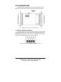
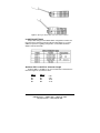
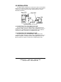
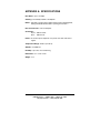
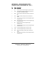
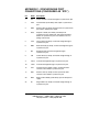
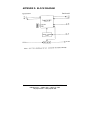
Not Recommended for New Installations.
Please contact Technical Support for more information.
Asynchronous to
Synchronous Converter
Model 2010
Documentation Number 2010AS3297
B&B Electronics Mfg. Co. Inc.
707 Dayton Road -- P.O. Box 1040 -- Ottawa, IL 61350
PH (815) 433-5100 -- FAX (815) 433-5105
Internet:
http://www.bb-elec.com
[email protected]
[email protected]
B&B Electronics -- September 1997
2010AS3297 Manual
Cover Page
B&B Electronics -- PO Box 1040 -- Ottawa, IL 61350
PH (815) 433-5100 -- FAX (815) 434-7094
Table of Contents
1.0 WARRANTY INFORMATION................................................... 1
1.1 RADIO AND TV INTERFERENCE ....................................... 1
1.2 SERVICE .............................................................................. 1
2.0 GENERAL INFORMATION ...................................................... 2
2.1 FEATURES........................................................................... 2
2.2 DESCRIPTION ..................................................................... 2
3.0 CONFIGURATION ................................................................... 3
3.1 SETTING INTERNAL SWITCHES........................................ 3
3.2 SWITCH SETTINGS............................................................. 4
Switches SW1-1 and SW1-2: Character Length ..................... 4
Switch SW1-3: Extended Signaling Rate (ESR) ..................... 5
4.0 INSTALLATION ........................................................................ 6
4.1 CONNECTING THE ASYNCHRONOUS PORT................... 6
4.2 CONNECTING THE SYNCHRONOUS PORT ..................... 6
APPENDIX A: SPECIFICATIONS ................................................. 7
APPENDIX B: ASYNCHRONOUS PORT CONNECTIONS
(CONFIGURED AS "DCE") ............................................................ 8
APPENDIX C: SYNCHRONOUS PORT CONNECTIONS
(CONFIGURED AS "DTE") ............................................................ 9
APPENDIX D: BLOCK DIAGRAM............................................... 10
2010AS3297 Manual
Table of Contents
B&B Electronics -- PO Box 1040 -- Ottawa, IL 61350
PH (815) 433-5100 -- FAX (815) 434-7094
i
1.0 WARRANTY INFORMATION
B&B Electronics warrants all Model 2010 components to be free from
defects, and will—at our option—repair or replace the product should it fail
within one year from the first date of shipment.
This warranty is limited to defects in workmanship or materials, and
does not cover customer damage, abuse or unauthorized modification. If
this product fails or does not perform as warranted, your sole recourse shall
be repair or replacement as described above. Under no condition shall B&B
Electronics be liable for any damages incurred by the use of this product.
These damages include, but are not limited to, the following: lost profits,
lost savings and incidental or consequential damages arising from the use
of or inability to use this product. B&B Electronics specifically disclaims all
other warranties, expressed or implied, and the installation or use of this
product shall be deemed as user’s acceptance of these terms.
1.1 RADIO AND TV INTERFERENCE
The Model 2010 generates and uses radio frequency energy, and if not
installed and used properly—that is, in strict accordance with the
manufacturer's instructions—may cause interference to radio and television
reception. The Model 2010 has been tested and found to comply with the
limits for a Class A computing device in accordance with the specifications
in Subpart J of Part 15 of FCC rules, which are designed to provide
reasonable protection from such interference in a commercial installation.
However, there is no guarantee that interference will not occur in a
particular installation. If the Model 2010 does cause interference to radio or
television reception, which can be determined by disconnecting the RS-232
interface, the user is encouraged to try to correct the interference by one or
more of the following measures: moving the computing equipment away
from the receiver, reorienting the receiving antenna and/or plugging the
receiving equipment into a different AC outlet (such that the computing
equipment and receiver are on different branches).
1.2 SERVICE
All warranty and non-warranty repairs must be returned freight prepaid
and insured to B&B Electronics. All returns must have a Return Materials
Authorization number on the outside of the shipping container. This number
may be obtained from B&B Electronics Customer Service at (815) 4335100. Packages received without an RMA number will not be accepted.
B&B Electronics' technical staff is available to answer any questions
that might arise concerning the installation or use of your Model 2010.
Technical Service hours: 8 AM to 5PM CST, Monday through Friday.
2010AS3297 Manual
B&B Electronics -- PO Box 1040 -- Ottawa, IL 61350
PH (815) 433-5100 -- FAX (815) 434-7094
1
2.0 GENERAL INFORMATION
Thank you for your purchase of this B&B Electronics product. This
product has been thoroughly inspected and tested and is warranted for one
year parts and labor. If any questions or problems arise during installation
or use of this product, please do not hesitate to contact B&B Electronics
Technical Support at (815) 433-5100.
2.1 FEATURES
•
•
•
•
•
•
•
•
•
Conforms to CCITT V.14 and V.22 standards
Adapts asynchronous terminals to synchronous modems and
multiplexers
Allows character lengths from 8 - 11 bits
Requires no AC power or batteries
Data rates to 19.2 Kbps
Automatically adjusts synchronous data rates
Miniature size
Accepts external clocking
Made in the USA
2.2 DESCRIPTION
The Model 2010 converter gives asynchronous hardware access to the
high speed capabilities of synchronous modems or multiplexers. The Model
2010 plugs directly into the asynchronous RS-232 DTE port and connects
via RS-232 cable to the synchronous DCE device.
Drawing power from the RS-232 interface, the Model 2010 needs no
AC power or batteries to operate and supports data rates to 19.2 Kbps.
Because the Model 2010 automatically adjusts the synchronous data rate
to match the asynchronous DTE's output rate, no data rate strapping is
necessary. The Model 2010 derives clocking externally from the clock of
the synchronous DCE, and imposes no limit on data block size. Characters
may be up to 11 bits long.
Measuring only 3.2" x 2.0" x .75", the Model 2010 is housed in a sturdy
ABS plastic case. It comes fully equipped with a DB-25 male connector and
a DB-25 female connector.
2
2010AS3297 Manual
B&B Electronics -- PO Box 1040 -- Ottawa, IL 61350
PH (815) 433-5100 -- FAX (815) 434-7094
3.0 CONFIGURATION
The Model 2010 is configured using four internal switches. Figure 1
shows the switch locations with respect to other PC board components.
Figure 1. Switch locations on the 2010 PC board
3.1 SETTING INTERNAL SWITCHES
The four switches shown in Figure 2 allow selection of character length
and extended signaling rate. These switches are located internally on the
Model 2010's PC board. To access them use a small flathead screwdriver
to pop open the Model 2010's case as shown in Figure 3.
Figure 2. Close-up of the Model 2010’s configuration switches
2010AS3297 Manual
B&B Electronics -- PO Box 1040 -- Ottawa, IL 61350
PH (815) 433-5100 -- FAX (815) 434-7094
3
Figure 3. Opening the Model 2010’s case with a small screwdriver
3.2 SWITCH SETTINGS
All possible settings for the Model 2010's configuration switches are
presented in the following summary table and descriptions. If you have
additional questions regarding configuration, contact B&B Technical
Support at (815) 433-5100.
Switches SW1-1 and SW1-2: Character Length
Switches SW1-1 and SW1-2 are set in combination to determine the
character length for asynchronous data.
SW 1-1
Off
On
Off
On
4
SW 1-2
On
On
Off
Off
8 bit
9 bit
10 bit
11 bit
2010AS3297 Manual
B&B Electronics -- PO Box 1040 -- Ottawa, IL 61350
PH (815) 433-5100 -- FAX (815) 434-7094
Switch SW1-3: Extended Signaling Rate (ESR)
The setting for switch 1-3 determines the range of variability the Model
2010 looks for in asynchronous data rates (i.e., the actual variance from a
given frequency level the Model 2010 will tolerate).
SW 1-3
Off
-2.5% to +1%
On
-2.5% to +2.3%
Switch SW1-4: Not Used
2010AS3297 Manual
B&B Electronics -- PO Box 1040 -- Ottawa, IL 61350
PH (815) 433-5100 -- FAX (815) 434-7094
5
4.0 INSTALLATION
The Model 2010 is designed to be used in pairs, with one unit installed
between an asynchronous DTE and a synchronous DCE on either end of a
synchronous communication link. Figure 4 (below) illustrates a typical
Model 2010 installation.
Figure 4. Typical Model 2010 application
4.1 CONNECTING THE ASYNCHRONOUS PORT
The asynchronous port of the Model 2010 is a DB-25 female and is
configured as "DCE". Therefore, it wants to talk to a DTE device such as a
terminal or PC. The Model 2010 may be plugged directly into the DB-25
serial port of a DTE or connected via "straight through" cable.
4.2 CONNECTING THE SYNCHRONOUS PORT
The synchronous port of the Model 2010 is a DB-25 male and is
configured as "DTE." Therefore, it wants to talk to a DCE device such as a
modem or multiplexer. The Model 2010 may be plugged directly into the
DB-25 serial port of a DCE or connected via "straight through" cable.
6
2010AS3297 Manual
B&B Electronics -- PO Box 1040 -- Ottawa, IL 61350
PH (815) 433-5100 -- FAX (815) 434-7094
APPENDIX A: SPECIFICATIONS
Data Rates: Up to 19.2 Kbps
Clocking: Provided by modem or multiplexer
Buffer: 4 bit RTS override feature empties buffers before dropping RTS,
making the Model 2010 usable in a polling environment
Data Transmission: Full or half duplex
Connectors:
Async.: DB-25 female
Sync.: DB-25 male
Power: No external power required; uses power from data and control
signals
Temperature Range: 0-60°C (32-140°F)
Altitude: 0-15,000 feet
Humidity: Up to 95% non-condensing
Dimensions: 3.2" x 2.0” x 0.75"
Weight: 2 oz.
2010AS3297 Manual
B&B Electronics -- PO Box 1040 -- Ottawa, IL 61350
PH (815) 433-5100 -- FAX (815) 434-7094
7
APPENDIX B: ASYNCHRONOUS PORT
CONNECTIONS (CONFIGURED AS “DCE”)
Pin
Name Description
1
FG
Frame Ground; connected straight to synchronous port
2
TXD
Transmit Data (to 2010); data input from asynchronous
port; input to the 2010 power supply
3
RXD
Receive Data (from 2010); data output to asynchronous
port
4
RTS
Request to Send (to 2010); input to the 2010 power
supply
5
CTS
Clear to Send (from 2010); connected straight through to
synchronous port
6
DSR
Data Set Ready (from 2010); connected straight through
to synchronous port
7
SG
Signal Ground; connected straight through to
synchronous port
8
CD
Carrier Detect (from 2010); connected straight through to
synchronous port
9
+DCV
Connected straight through to synchronous port
10
-DCV
Connected straight through to synchronous port
20
DTR
Data Terminal Ready (to 2010); input to 2010 power
supply
22
Rl
Ring Indicator (from 2010); connected straight through to
synchronous port
8
2010AS3297 Manual
B&B Electronics -- PO Box 1040 -- Ottawa, IL 61350
PH (815) 433-5100 -- FAX (815) 434-7094
APPENDIX C: SYNCHRONOUS PORT
CONNECTIONS (CONFIGURED AS “DTE”)
Pin
Name
Description
1
FG
Frame Ground; connected straight to asynchronous port
2
TXD
Transmit Data (from 2010); data output to synchronous
port
3
RXD
Receive Data (to 2010); data input from the synchronous
port; input to 2010 power supply
4
RTS
Request to Send (from 2010); 4 bit delay from
asynchronous port (2010 waits 4 bits before dropping
RTS to the synchronous port; this facilitates use in a
polling environment)
5
CTS
Clear to Send (to 2010); connected straight through to
asynchronous port
6
DSR
Data Set Ready (to 2010); connected straight through to
asynchronous port
7
SG
Signal Ground; connected straight through to
asynchronous port
8
CD
Carrier Detect (to 2010); connected straight through to
asynchronous port
9
+DCV
Connected straight through to asynchronous port
10
–DCV
Connected straight through to asynchronous port
15
TXC
Transmit clock (to 2010); used to synchronize data
conversion from 2010 to synchronous port
17
RXC
Receive clock (to 2010); used to synchronize data
conversion from 2010 to synchronous port
20
DTR
Data Terminal Ready (from 2010); input to 2010 power
supply
22
Rl
Ring Indicator (to 2010); connected straight through to
asynchronous port
2010AS3297 Manual
B&B Electronics -- PO Box 1040 -- Ottawa, IL 61350
PH (815) 433-5100 -- FAX (815) 434-7094
9
APPENDIX D: BLOCK DIAGRAM
10
2010AS3297 Manual
B&B Electronics -- PO Box 1040 -- Ottawa, IL 61350
PH (815) 433-5100 -- FAX (815) 434-7094