1
BCM Rls 6.0
WLAN IP Telephony Configuration
Task Based Guide
WLAN IP Telephony Configuration
Copyright © 2010 Avaya Inc.
All Rights Reserved.
Notices
While reasonable efforts have been made to ensure that the information in this document is complete and accurate
at the time of printing, Avaya assumes no liability for any errors. Avaya reserves the right to make changes and
corrections to the information in this document without the obligation to notify any person or organization of such
changes.
Documentation disclaimer
Avaya shall not be responsible for any modifications, additions, or deletions to the original published version of
this documentation unless such modifications, additions, or deletions were performed by Avaya. End User agree to
indemnify and hold harmless Avaya, Avaya’s agents, servants and employees against all claims, lawsuits, demands
and judgments arising out of, or in connection with, subsequent modifications, additions or deletions to this
documentation, to the extent made by End User.
Link disclaimer
Avaya is not responsible for the contents or reliability of any linked Web sites referenced within this site or
documentation(s) provided by Avaya. Avaya is not responsible for the accuracy of any information, statement or
content provided on these sites and does not necessarily endorse the products, services, or information described or
offered within them. Avaya does not guarantee that these links will work all the time and has no control over the
availability of the linked pages.
Warranty
Avaya provides a limited warranty on this product. Refer to your sales agreement to establish the terms of the
limited warranty. In addition, Avaya’s standard warranty language, as well as information regarding support for
this product, while under warranty, is available to Avaya customers and other parties through the Avaya Support
Web site: http://www.avaya.com/support
Please note that if you acquired the product from an authorized reseller, the warranty is provided to you by said
reseller and not by Avaya.
Licenses
THE SOFTWARE LICENSE TERMS AVAILABLE ON THE AVAYA WEBSITE,
HTTP://SUPPORT.AVAYA.COM/LICENSEINFO/ ARE APPLICABLE TO ANYONE WHO DOWNLOADS,
USES AND/OR INSTALLS AVAYA SOFTWARE, PURCHASED FROM AVAYA INC., ANY AVAYA
AFFILIATE, OR AN AUTHORIZED AVAYA RESELLER (AS APPLICABLE) UNDER A COMMERCIAL
AGREEMENT WITH AVAYA OR AN AUTHORIZED AVAYA RESELLER. UNLESS OTHERWISE
AGREED TO BY AVAYA IN WRITING, AVAYA DOES NOT EXTEND THIS LICENSE IF THE
SOFTWARE WAS OBTAINED FROM ANYONE OTHER THAN AVAYA, AN AVAYA AFFILIATE OR AN
AVAYA AUTHORIZED RESELLER, AND AVAYA RESERVES THE RIGHT TO TAKE LEGAL ACTION
AGAINST YOU AND ANYONE ELSE USING OR SELLING THE SOFTWARE WITHOUT A LICENSE. BY
INSTALLING, DOWNLOADING OR USING THE SOFTWARE, OR AUTHORIZING OTHERS TO DO SO,
YOU, ON BEHALF OF YOURSELF AND THE ENTITY FOR WHOM YOU ARE INSTALLING,
DOWNLOADING OR USING THE SOFTWARE (HEREINAFTER REFERRED TO INTERCHANGEABLY
AS "YOU" AND "END USER"), AGREE TO THESE TERMS AND CONDITIONS AND CREATE A
BINDING CONTRACT BETWEEN YOU AND AVAYA INC. OR THE APPLICABLE AVAYA AFFILIATE
("AVAYA").
Copyright
Except where expressly stated otherwise, no use should be made of the Documentation(s) and Product(s) provided
by Avaya. All content in this documentation(s) and the product(s) provided by Avaya including the selection,
arrangement and design of the content is owned either by Avaya or its licensors and is protected by copyright and
other intellectual property laws including the sui generis rights relating to the protection of databases. You may not
modify, copy, reproduce, republish, upload, post, transmit or distribute in any way any content, in whole or in part,
including any code and software. Unauthorized reproduction, transmission, dissemination, storage, and or use
without the express written consent of Avaya can be a criminal, as well as a civil offense under the applicable law.
Third Party Components
Certain software programs or portions thereof included in the Product may contain software distributed under third
party agreements ("Third Party Components"), which may contain terms that expand or limit rights to use certain
portions of the Product ("Third Party Terms"). Information regarding distributed Linux OS source code (for those
Products that have distributed the Linux OS source code), and identifying the copyright holders of the Third Party
Components and the Third Party Terms that apply to them is available on the Avaya Support Web site:
http://support.avaya.com/Copyright.
Trademarks
The trademarks, logos and service marks ("Marks") displayed in this site, the documentation(s) and product(s)
provided by Avaya are the registered or unregistered Marks of Avaya, its affiliates, or other third parties. Users
are not permitted to use such Marks without prior written consent from Avaya or such third party which may own
the Mark. Nothing contained in this site, the documentation(s) and product(s) should be construed as granting, by
implication, estoppel, or otherwise, any license or right in and to the Marks without the express written permission
of Avaya or the applicable third party. Avaya is a registered trademark of Avaya Inc. All non-Avaya trademarks
are the property of their respective owners.
2
NN40011-038 Issue 1.2 BCM Rls 6.0
WLAN IP Telephony Configuration
Downloading documents
For the most current versions of documentation, see the Avaya Support. Web site: http://www.avaya.com/support
Contact Avaya Support
Avaya provides a telephone number for you to use to report problems or to ask questions about your product. The
support telephone number is 1-800-242-2121 in the United States. For additional support telephone numbers, see
the Avaya Web site: http://www.avaya.com/support
Copyright © 2010 ITEL, All Rights Reserved
The copyright in the material belongs to ITEL and no part of the material may
be reproduced in any form without the prior written permission of a duly
authorised representative of ITEL.
NN40011-038 Issue 1.2 BCM Rls 6.0
3
WLAN IP Telephony Configuration
Table of Contents
WLAN IP Telephony Configuration .................................. 6
Overview .......................................................................................... 6
Required Information / Equipment ................................................... 7
Flow Chart ....................................................................................... 8
WLAN IP Telephony Manager 2245 ................................................ 9
Rack-mounting the WLAN IP Telephony Manager 2245...................................9
Wall Mounting ..................................................................................................10
Rack-Mounting .................................................................................................10
To Rack-Mount the WLAN IP Telephony Manager 2245 ................................10
Connecting the WLAN IP Telephony Manager 2245 to the LAN and Power
up Procedure. ..................................................................................................11
Installation...................................................................................... 12
Accessing Business Element Manager ...........................................................12
Business Communications Manager Parameters .......................... 15
2245 WLAN Telephony Server IP Address and TFTP Server Parameters .....15
Licensing on the Business Communications Manager (BCM) ........................17
IP Terminals Registration. ...............................................................................18
Connecting to the WLAN IP Telephony Manager 2245 ................. 19
Connecting through a serial port ......................................................................20
Configuring Network Parameters.....................................................................22
Configuring the SVP-II .....................................................................................28
Downloading the WLAN IP Telephony handset firmware .............. 35
Pre-download Checklist ...................................................................................35
Screen and Button Layout on a 2210 Handset ................................................36
Downloading the firmware ...............................................................................36
Admin Menus and Registration of WLAN Handsets ...................... 37
Accessing the Main Admin Menus ...................................................................38
Phone Config Menus .......................................................................................38
Network Config Menus ....................................................................................39
Diagnostics Menu ............................................................................................40
Registering the WLAN Handsets ................................................... 40
General Navigation ..........................................................................................40
Registering a Handset .....................................................................................41
Full Admin Menu options ............................................................... 44
Configuring the idle state display .....................................................................50
4
NN40011-038 Issue 1.2 BCM Rls 6.0
WLAN IP Telephony Configuration
WLAN Handset Error Messages .................................................... 50
Avaya Documentation Links .......................................... 58
NN40011-038 Issue 1.2 BCM Rls 6.0
5
WLAN IP Telephony Configuration
WLAN IP Telephony Configuration
Overview
A Wireless LAN (WLAN) refers to a computer Local Area Network that has
wireless components. It is also referred to as WiFi (Wireless Fidelity) and is a
standard that allows computer devices to connect to a network literally without
wires. WLAN IP Telephony is the ability to send voice packets across the
existing Wireless LAN Computer network, so it is sharing the same bandwidth
and connections as the Data Traffic. WLAN IP Telephony is a wireless
mobility solution which uses the 802.11b wireless platform.
The Wireless Local Area Network Handsets 2210, 2211 2212 operate over an
802.11b wireless Ethernet LAN providing users a wireless Voice over IP
(VoIP) solution.
To be able to connect to the Business Communications Manager (BCM), the
WLAN IP Telephony Handsets must be supplied with the IP Address of the
WLAN IP Telephony Manager 2245 and, optionally, a Trivial File Transfer
Protocol (TFTP) Server. The WLAN Handsets accept IP Address
configuration parameters either from manual configuration or from a Dynamic
Host Configuration Protocol (DHCP) Server. DHCP automatic discovery mode
provides the WLAN IP Telephony Manager 2245 and TFTP Server IP
addresses to the WLAN Handsets. The BCM can be the DHCP Server, or a
separate DHCP Server can be provided in the network.
The 802.11b protocol provides no mechanism for differentiating audio packets
from data packets. The WLAN IP Telephony Manager 2245 provides a Quality
of Service (QOS) mechanism that is implemented in the WLAN Handsets and
the Access Points (APs) to enhance voice quality over the wireless network.
The WLAN IP Telephony Manager 2245 gives preference to voice packets
over data packets on the wireless medium, increasing the probability that all
voice packets are transmitted efficiently and with minimum or no delay.
The WLAN IP Telephony Handsets 2210/2211/2212 use the TFTP Server to
update the wireless telephone firmware over the 802.11b WLAN.
6
NN40011-038 Issue 1.2 BCM Rls 6.0
WLAN IP Telephony Configuration
The basic WLAN IP Telephony network consists of the following components:
Business Communications Manager
TFTP Server (optional)
DHCP Server (optional)
WLAN IP Telephony Manager 2245
WLAN Handset 2210/2211/2212/6120/6140
Access Point (AP)
Required Information / Equipment
To support the WLAN IP Telephony / Handsets:
The BCM system must run Release 3.6.1 (patch) or later software
versions. BCM systems with 3.6 or earlier software versions must be
upgraded to support the handsets.
BCM50 Release 2 or later will support WLAN IP Telephony.
BCM450 Release 1 or later will also support WLAN IP Telephony.
A TFTP Server is required to distribute firmware to the WLAN Handsets
and WLAN IP Telephony Manager 2245. It can reside on a different
subnet than the BCM and APs. The TFTP Server can be located on
either side of the firewall.
Telephony Programming must be completed on the BCM.
IP Clients keycode must be installed on the BCM.
IP Terminal Registration must be enabled on the BCM.
A range of IP Addresses is required to be assigned to each handset for
recognition by the BCM
A range of additional IP Addresses is required to be assigned to each
handset by the WLAN IP Telephony Manager 2245.
NN40011-038 Issue 1.2 BCM Rls 6.0
7
WLAN IP Telephony Configuration
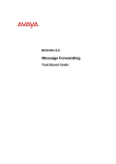
Flow Chart
The flow chart below shows a recommended order for configuring WLAN IP
Telephony.
Install the WLAN IP Telephony
Manager 2245: refer to the WLAN
IP Telephony Manager 2245
section of this guide.
Download the firmware to the
WLAN Handsets: refer to the
Downloading the WLAN
Handset handset firmware
section of this guide.
Connect to the WLAN IP
Telephony Manager 2245: refer to
the Connecting to the WLAN IP
Telephony Manager 2245 section
of this guide.
Configure the WLAN Handsets:
refer to the Admin Menus and
Registration of the WLAN
Handsets section of this guide.
Configure the WLAN IP Telephony
Manager 2245 Network settings:
refer to the Configuring Network
Parameters section of this guide.
Configure the WLAN IP Telephony
Manager 2245 SVP-II settings:
refer to the Configuring the
SVP-II section of this guide.
8
NN40011-038 Issue 1.2 BCM Rls 6.0
WLAN IP Telephony Configuration
WLAN IP Telephony Manager 2245
The WLAN IP Telephony Manager 2245 manages IP telephony network traffic
on the WLAN system. It is required to utilize the 11 Mb/s maximum
transmission speed available in the handsets. The WLAN IP Telephony
provides a number of services including a QoS mechanism, AP bandwidth
management, and efficient RF link utilization. It also acts as a Proxy for the
WLAN Handsets.
The WLAN IP Telephony Manager 2245 works with the APs to provide QoS
on the WLAN. All voice packets are encapsulated by the wireless handsets.
The encapsulated voice packets to and from the wireless handsets are
handled by the WLAN IP Telephony Manager 2245 and routed to and from
the BCM. SpectraLink Voice Priority gives preference to voice packets over
data packets on the wireless network, increasing the probability that voice
packets are transmitted with minimum delay.
Each subnet where the wireless handsets will operate requires at least one
WLAN IP Telephony Manager 2245. The Telephony Manager must therefore
be located in the same subnet as the wireless handsets. One unit can process
80 simultaneous calls. If greater capacity is required, multiple units can be
utilised.
Each WLAN IP Telephony Manager 2245 is shipped with one Class II AC
adapter with 24 volt (V) DC, 1 amp (A) output.
Rack-mounting the WLAN IP Telephony Manager 2245
1. Remove the corner screws from the WLAN IP Telephony Manager
2245.
2. Screw the U-shaped end (round screw holes) of the two mounting
plates to the WLAN IP Telephony Manager 2245.
NN40011-038 Issue 1.2 BCM Rls 6.0
9
WLAN IP Telephony Configuration
3. Screw the other end of the two mounting plates (oblong screw holes) to
the rack.
4. Repeat steps 1-3 for each additional WLAN IP Telephony Manager
2245. The mounting plate is designed to provide the correct minimum
spacing between units. When mounting multiple units, stack the units in
the rack as closely as possible.
Wall Mounting
The WLAN IP Telephony Manager 2245 can be mounted either vertically or
horizontally.
To wall-mount the WLAN IP Telephony Manager 2245:
1. Use a 1/8-inch drill bit to drill four holes. The holes should be on 1.84
by 12.1 inch centers.
2. Insert the #8 x 3/4-inch screws in the holes and tighten, leaving a 1/8 to
1/4-inch gap from the wall.
3. Slide the WLAN IP Telephony Manager 2245 over the screws until the
WLAN IP Telephony Manager 2245 drops into place in the keyhole
openings of the flange.
4. Tighten screws fully.
Rack-Mounting
The rack-mount kit is designed for mounting the WLAN IP Telephony
Manager 2245 in a standard 19-inch rack. The following equipment is required
and supplied:
1. Mounting plates: two plates are required for the WLAN IP Telephony
Manager 2245 to be mounted.
2. Screws: four rack-mount screws are required for each WLAN IP
Telephony Manager 2245 to be mounted.
To Rack-Mount the WLAN IP Telephony Manager 2245
1. Remove the corner screws from the WLAN IP Telephony Manager
2245.
2. Screw the U-shaped end (round screw holes) of the two mounting
plates to the WLAN IP Telephony Manager 2245.
3. Screw the other end of the two mounting plates (oblong screw holes) to
the rack.
10
NN40011-038 Issue 1.2 BCM Rls 6.0
WLAN IP Telephony Configuration
4. Repeat steps 1-3 for each additional WLAN IP Telephony Manager
2245. The mounting plate is designed to provide the correct minimum
spacing between units. When mounting multiple units, stack the units in
the rack as closely as possible.
Connecting the WLAN IP Telephony Manager 2245 to the LAN
and Power up Procedure.
The WLAN IP Telephony Manager 2245 can now be connected to the LAN.
1. To connect to the LAN insert a RJ-45 cable to the Network Port of the
WLAN IP Telephony Manager 2245. This cable should also be
connected to a port on a Ethernet Switch.
2. To power the WLAN IP Telephony Manager 2245 insert the AC power
adapter into the PWR jack of the WLAN IP Telephony Manager 2245.
Then plug the AC Adaptor into a 110vAC outlet.
NN40011-038 Issue 1.2 BCM Rls 6.0
11
WLAN IP Telephony Configuration
Installation
Accessing Business Element Manager
Element Manager is required to perform some of the BCM’s configuration in
relation to WLAN IP Telephony. If not installed please refer to the Installing
Business Element Manager section of the Business Element Manager
Guide.
1. To access the Business Element Manager application from the Start
Menu,
navigate
to
Start,
Programs,
Avaya,
Business
Communications Manager, Business Element Manager.
2. Alternatively, double-click on the Business Element Manager desktop
icon.
12
NN40011-038 Issue 1.2 BCM Rls 6.0
WLAN IP Telephony Configuration
3. You will be presented with the Element Manager interface.
4. Open the Network Elements folder and select the IP Address of the
BCM.
5. Enter the User Name of the BCM in the User Name field, by default this
is nnadmin. Then enter the Password in the Password field, by default
the password is PlsChgMe!. Click the Connect button.
NN40011-038 Issue 1.2 BCM Rls 6.0
13
WLAN IP Telephony Configuration
6. A warning screen will appear, read the warning and click OK.
7. You will be presented with the Element Manager interface.
14
NN40011-038 Issue 1.2 BCM Rls 6.0
WLAN IP Telephony Configuration
Business Communications Manager Parameters
There are certain parameters that need to be checked and configured within
the Business Communications Manager itself. The Business Communications
Manager system has to reference the IP address of the SVP Server and the
IP address of the TFTP Server where for example firmware for the handsets is
contained. There also has to be an adequate number of IP clients keycoded
for the WLAN handsets to utilise. These details can be found by using the
Element Manager application.
2245 WLAN Telephony Server IP Address and TFTP Server
Parameters
1. Login to the BCM via Element Manager.
2. From the Configuration tab open the Data Services folder, select the
DHCP Server link and select the IP Terminal DHCP options tab.
NN40011-038 Issue 1.2 BCM Rls 6.0
15
WLAN IP Telephony Configuration
3. In the Avaya WLAN Handsets Settings portion of the screen enter the
IP address of the TFTP Server in the TFTP Server field.
4. Then enter the IP address of the WLAN IP Telephony Manager 2245
in the associated field.
.
16
NN40011-038 Issue 1.2 BCM Rls 6.0
WLAN IP Telephony Configuration
Licensing on the Business Communications Manager (BCM)
You will need to ensure that valid licence files for IP Clients (WLAN handsets)
have been added to the BCM.
1. From within Element Manager select the Configuration tab and open
the System folder. Then select the Keycodes link.
2. Check that there are adequate seats for the IP Clients. These will be
used by the WLAN handsets. If there are not adequate licences
available then a key code file will have to be obtained from Avaya and
loaded on to the BCM system. Please refer to the Business
Communications Manager 450 / 50 System Start Up Guide for details
of how to load a licence file.
NN40011-038 Issue 1.2 BCM Rls 6.0
17
WLAN IP Telephony Configuration
IP Terminals Registration.
In order for each of the wireless handset to register as a DN with the BCM
system, IP Terminal Registration has to be enabled on the BCM itself.
1. From within Element Manager select the Configuration tab then open
the Resources folder and select the Telephony Resources link.
18
NN40011-038 Issue 1.2 BCM Rls 6.0
WLAN IP Telephony Configuration
2. Select the IP Sets tab. In the lower details section of the screen ensure
that the Enable Registration check box is ticked. This will enable
registration of the WLAN IP handsets to take place.
3. You should select the Enable global registration password option
and enter a numerical password in the Global password field. This
password must be entered on the handsets during registration.
Connecting to the WLAN IP Telephony Manager 2245
The initial connection to the WLAN IP Telephony Manager 2245 must be
made through a serial connection to establish the IP address of the WLAN IP
Telephony Manager 2245 and the maximum number of active calls per
access point. Further configuration and administration can be performed at a
later time through a Telnet connection.
NN40011-038 Issue 1.2 BCM Rls 6.0
19
WLAN IP Telephony Configuration
Connecting through a serial port
1. Connect the WLAN IP Telephony Manager 2245 to the serial port of a
terminal or PC using a DB-9 female, null-modem cable.
2. Run a terminal emulation program (such as HyperTerminal.), or use a
VT-100 terminal with the following configuration:
3. Press Enter to display the login screen.
20
NN40011-038 Issue 1.2 BCM Rls 6.0
WLAN IP Telephony Configuration
4. Enter the default login name (admin) and the default password
(admin). The login name and password are case-sensitive.
5. The NetLink SVP-II System menu appears.
NN40011-038 Issue 1.2 BCM Rls 6.0
21
WLAN IP Telephony Configuration
Configuring Network Parameters
1. Use the keyboards up & down arrows and select Network
Configuration from the NetLink SVP-II System menu.
2. The Network Configuration screen appears.
22
NN40011-038 Issue 1.2 BCM Rls 6.0
WLAN IP Telephony Configuration
3. Highlight the individual headings and press the Enter key to make the
required changes. Configure the parameters as per the following steps:
4. IP Address: Enter the complete IP address for the WLAN IP Telephony
Manager 2245, including digits and periods. In the example below the 2245
Telephony Manager has been given an IP address of 20.20.20.45
5. Hostname: Change the hostname of this 2245, if desired. Hostname
is for identification purposes only.
6. Subnet mask: Enter the subnet mask for the 2245.
NN40011-038 Issue 1.2 BCM Rls 6.0
23
WLAN IP Telephony Configuration
7. Default Gateway. Enter the default gateway for this particular subnet
that the 2245 Telephony Manager resides on.
8. SVP-II TFTP Download Master. Enter the IP address of the TFTP
Server where the firmware update files are saved. Enter one of the
following:
i. NONE disables this function
ii. The TFTP server IP address. IP address of the TFTP
Server that transfers firmware updates to the 2245.
24
NN40011-038 Issue 1.2 BCM Rls 6.0
WLAN IP Telephony Configuration
9. Primary DNS Server, Secondary DNS Server, DNS Domain. Used to
configure DNS. Obtain the settings from the network administrator.
Optionally, enter DHCP. This enables the DHCP client in the 2245 to
attempt to automatically obtain a valid IP address from the DHCP
Server. The DHCP setting is only valid when the IP address is obtained
from DHCP.
10. WINS Server. The IP address of the Windows Name Services (WINS)
Server. Obtain the settings from the network administrator. Optionally,
enter DHCP. As with DNS, this enables the DHCP client in the 2245 to
attempt to automatically obtain a valid IP address from the DHCP
Server. When WINS is configured, the 2245 can translate hostnames
to IP addresses. This means that using Telnet, the 2245 can be
accessed using its hostname rather than its IP address.
NN40011-038 Issue 1.2 BCM Rls 6.0
25
WLAN IP Telephony Configuration
11. Syslog Server. The IP address of the server where the system logs
are written for the WLAN IP Telephony Manager 2245. If a Syslog
Server is configured, a message is sent to the Syslog Server when an
alarm is generated. Enter one of the following:
iii. NONE disables this function
iv. The IP address of the Syslog Server
12. Maintenance Lock indicates if the WLAN IP Telephony Manager 2245
is in Maintenance Lock mode.
26
NN40011-038 Issue 1.2 BCM Rls 6.0
WLAN IP Telephony Configuration
13. SendAll. In a scenario that has multiple 2245s, the SendAll option is
provided to speed configuration and ensure identical settings. The
S=SendAll option enables configuration parameters of the selected
field to be sent to every 2245 on the LAN.
Note: SendAll can only be used after the IP address is configured on each
2245 using a serial connection. If identical configuration parameters are to
be used for all 2245s, configure only the IP address and custom hostname
(if desired) on each 2245 using the initial serial connection. Then connect
through the LAN to this 2245 and use SendAll to transmit identical
configuration options of each field to all WLAN IP Telephony Managers
2245.
14. Reset the WLAN IP Telephony Manager 2245 in order to save the
configuration parameters.
15. Press Esc on the keyboard. If the system is in Maintenance Lock you
will be prompted to save the configuration enter Y.
NN40011-038 Issue 1.2 BCM Rls 6.0
27
WLAN IP Telephony Configuration
16. The configuration can also be saved by selecting Reset from the SVPII Configuration screen.
Configuring the SVP-II
The WLAN IP Telephony Manager 2245 acts as a proxy for every wireless
handset. This means that except for the initial DHCP allocation for example
from the BCM and TFTP firmware check sessions from a TFTP PC, the
handsets only communicate with the WLAN IP Telephony Manager 2245.
Each WLAN IP Telephony Manager 2245 is configured with an IP address
with which all of the wireless handsets communicate. In addition, each WLAN
IP Telephony Manager 2245 is configured with a pool of ‘alias’ IP addresses.
When a wireless handset registers with a WLAN IP Telephony Manager 2245,
the wireless handset is assigned one of the ‘alias’ IP addresses from the pool.
All communication between this WLAN IP Telephony Manager 2245 and other
devices (TPS, IP Phones, gateways, and other wireless handsets) is always
completed through its pool of ‘alias’ IP address that it can assign to these
devices. Therefore, the WLAN IP Telephony Manager 2245 acts in a similar
way to NAT (Network Address Translation).
The number of simultaneous calls that can be supported by compatible
access points can also be configured. All of these settings can be configured
from the SVP- II Configuration interface.
28
NN40011-038 Issue 1.2 BCM Rls 6.0
WLAN IP Telephony Configuration
1. Select SVP-II Configuration from the NetLink SVP-II System menu to
configure additional settings for WLAN IP Telephony Manager 2245.
2. The SVP II Configuration screen will be displayed.
NN40011-038 Issue 1.2 BCM Rls 6.0
29
WLAN IP Telephony Configuration
3. Configure the following fields with information provided by the network
administrator:
4. Phones per Access Point. Enter the number of simultaneous calls
supported for the type of AP. This limits the number of calls per Access
Point, ensuring adequate bandwidth availability for voice and data
transmissions.
5. 802.11 Rate. Select Automatic to allow the wireless handset to
determine its rate (up to 11Mbit/s). Select 1MB/2MB to limit the
transmission rate between the wireless handsets and APs.
30
NN40011-038 Issue 1.2 BCM Rls 6.0
WLAN IP Telephony Configuration
6. SVP-II Master. The IP address of the master of the WLAN IP
Telephony Manager 2245 group must be identified. Select one of the
following identification options:
i. Enter the IP address of the master of the 2245 in each
2245 group. Include the periods used in the IP address.
ii. Enter DHCP. Ensure that the IP address of the master
2245 has been configured in the DHCP Server and
configure the other 2245s to obtain the information from
the DHCP Server.
iii. Enter DNS. Ensure that the IP address of the master
2245 has been configured in the DNS Server and
configure the other 2245s to retrieve this information from
the DNS Server.
In this example an IP address of 20.20.20.45 has been entered for the SVP –
II Master.
NN40011-038 Issue 1.2 BCM Rls 6.0
31
WLAN IP Telephony Configuration
7. First Alias IP Address/Last Alias IP Address. Enter the range of IP
addresses that this WLAN IP Telephony Manager 2245 can use when
acting as a proxy for the wireless handsets.
a. All alias addresses must be on the same subnet as the 2245.
The IP addresses cannot be duplicated on other subnets or
2245s. There is no limit to the number of IP addresses that can
be assigned, but the capacity of each 2245 is 500 wireless
handsets.
8. SVP-II Mode. Select NetLink IP.
32
NN40011-038 Issue 1.2 BCM Rls 6.0
WLAN IP Telephony Configuration
9. Ethernet link. This should be left as auto-negotiate unless there is a
specific need to specify the link speed.
10. System Locked. Use this option to allow the system to enter a
maintenance state. The default is N (No). Select Y (Yes) to prevent
any new calls from starting. Enter N to restore normal operation.
NN40011-038 Issue 1.2 BCM Rls 6.0
33
WLAN IP Telephony Configuration
11. Maintenance Lock. The system automatically sets this option to Y
after certain maintenance activities that will require a reset. Examples
of this are changing the IP address of the SVP.
Note: Maintenance Lock prevents any new calls from starting. Reset the
system at exit to clear Maintenance Lock.
12. Reset. If this option is selected, a prompt appears to reset the WLAN
IP Telephony Manager 2245 when exiting the SVP-II Configuration
screen.
34
NN40011-038 Issue 1.2 BCM Rls 6.0
WLAN IP Telephony Configuration
13. The WLAN IP Telephony Manager will then reboot. The configuration
changes will be saved and any new firmware from the TFTP server will
be downloaded.
14. Reset all SVP servers. If this option is selected, all WLAN IP
Telephony Managers 2245 on the subnet are reset.
Note: You should always reset the WLAN IP Telephony Manager 2245 in
order to save the configuration parameters.
Downloading
firmware
the
WLAN
IP
Telephony
handset
All WLAN Handsets 2210/2211 are shipped with a generic firmware load that
allows them to associate to a WLAN and download their functional firmware
from a TFTP Server. The wireless handsets do not function properly without
downloading their appropriate firmware.
Pre-download Checklist
The following requirements must be met to download firmware:
Wireless LAN must be properly configured and operational through the
use of 802.11b SVP-compliant wireless APs.
The WLAN IP Telephony Manager 2245 must be connected to the
network and completely operational.
NN40011-038 Issue 1.2 BCM Rls 6.0
35
WLAN IP Telephony Configuration
TFTP Server must be available on the network to load the appropriate
firmware into the wireless handsets.
The ESSID (you can get this from the AP installer) should be available.
The IP addresses of the WLAN IP Telephony Manager 2245 and TFTP
server to configure the handsets is required.
The battery within the wireless handsets must be fully charged.
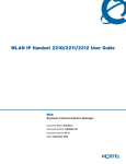
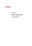
Screen and Button Layout on a 2210 Handset
Note: The 2210, 2211 and 2212 have the same screen and button layout.
Downloading the firmware
1. Download the latest WLAN Handsets 2210/2211 firmware (.zip file)
from the Avaya web site.
2. Extract the five firmware files from the .zip file and place them on the
TFTP Server. Ensure the TFTP Server is on before completing the
following steps.
3. If statically assigning IP addresses, ensure that the wireless handset IP
address, TFTP Server IP address, Subnet Mask, and Default Gateway
36
NN40011-038 Issue 1.2 BCM Rls 6.0
WLAN IP Telephony Configuration
information are accurate in the Admin Menu of the wireless handset. If
using a DHCP Server, ensure that the DHCP options are configured.
4. Ensure the wireless handset has properly configured ESSID and Reg
Domain Information within the Admin Menu. If broadcast ESSIDs are
accepted at the APs, the handset automatically learns the ESSID
information when powering on.
5. Using the Admin Menu on the wireless handset, ensure the License
Management menu option is set to 010. This ensures the handset will
check for the proper UNIStim firmware files each time it powers on.
6. Power on the wireless handset. The firmware now downloads to the
wireless handset. The status bar increments fully across the wireless
handset display for each function that is being performed in the
download process. Upon completion of the update process, the
wireless handset re-boots with the new firmware.
7. Register the wireless handset with the BCM as if it were an IP Phone
2004.
8. Properly label the wireless handset with the appropriate extension
number.
9. For future firmware upgrades, simply update the firmware files that are
stored on the TFTP Server. Each time the wireless handset is powered
on, it checks with the TFTP Server to ensure it has the proper firmware
version. It downloads the new firmware, when found.
Admin Menus and Registration of WLAN Handsets
Each Wireless handset can be partly administered from the handset itself
using an Admin menu structure. The Admin menu contains locally stored
configuration options for each handset.
WLAN handset configuration is performed after the WLAN IP Telephony
Manager 2245 has been installed and configured. The steps to configure a
WLAN handset must be performed for each wireless handset.
Provision the WLAN Handsets 2210/2211/2212 on the BCM system in the
same manner as an IP Phone 2004. Ensure you have the BCM firmware
download completed before configuring the handsets.
The Admin Menu contains configuration options that are stored locally on
each wireless handset.
NN40011-038 Issue 1.2 BCM Rls 6.0
37
WLAN IP Telephony Configuration
Every wireless handset is independent. If the default settings are not
appropriate, the Admin options must be configured in each handset that
requires different settings.
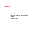
Accessing the Main Admin Menus
Phone Config Menus
38
NN40011-038 Issue 1.2 BCM Rls 6.0
WLAN IP Telephony Configuration
Network Config Menus
NN40011-038 Issue 1.2 BCM Rls 6.0
39
WLAN IP Telephony Configuration
Diagnostics Menu
Registering the WLAN Handsets
General Navigation
1. Press the UP or DOWN arrow keys (left side buttons) to scroll through
the menu options
2. Press SELECT (middle button on the left side) to edit or select an
option OR the soft key indicating OK
3. Press soft key indicating UP to return to the previous menu level
4. Press soft key indicating SAVE to save the setting
40
NN40011-038 Issue 1.2 BCM Rls 6.0
WLAN IP Telephony Configuration
5. Press soft key indicating EXIT to exit the menus
6. An asterisk (*) next to an option indicates that it is selected
The following illustrations outline the general procedure to register a WLAN
handset. Please note that these steps are the minimum that are required.
Therefore for detailed configuration options please refer to the Full Admin
Menu Options section of this guide.
Registering a Handset
1. With the wireless handset powered OFF, simultaneously press and
hold the Power On/Start Call and Power Off/End Call keys.
2. Release the Power On/Start Call key, then release the Power
Off/End Call key. The first option on the Admin Menu appears. Press
the Up and Down keys on the left side of the set to scroll through the
menu options.
NN40011-038 Issue 1.2 BCM Rls 6.0
41
WLAN IP Telephony Configuration
License Management
3. License Type 010 is required for handsets to register successfully with
the correct VoIP protocol. No other licence type is supported as this
can cause the phone to malfunction.
IP Settings
4. These settings determine the modes in which the WLAN handset can
operate i.e within a DHCP or Static IP address environments and also
which BCM and WLAN Telephony Manager 2245 to register with.
42
NN40011-038 Issue 1.2 BCM Rls 6.0
WLAN IP Telephony Configuration
ESSID and Regulatory Domain Settings
5. The ESSID setting will allow the handset to be recognised by an
Access Point with the same ESSID. This can be ‘Learnt’ or set as a
Static Entry. The Regulatory domain also needs to be defined for the
region that the WLAN handsets will reside. This can be entered by
selecting the LINE key.
Updating Code
6. The handset will now follow a sequence to update the firmware and
register with the BCM. No user intervention is required at this point.
NN40011-038 Issue 1.2 BCM Rls 6.0
43
WLAN IP Telephony Configuration
Full Admin Menu options
The following lists the Admin Menu options. Detailed descriptions of each
option follow the table.
Note: The IP Handsets 2210/2211/2212 configuration menu can differ from
the items listed in the table if the firmware has not been updated. Refer to the
guide that accompanies the handset for configuration settings until the
firmware is updated.
Admin Menu 2nd Level
Option
3rd Level
4th Level
Phone Config
Set Current
rd
1I2004 / 3
Party
Enable OIA
Disable OIA
Allowed
Channels
Allow /
Disallow
Enter PW
List per download
Licence Option
Terminal Type
OIA/ On/ OFF
Push to Talk
Admin
Password
Network Config
IP Address
Use DHCP
Static Entry
Svr1
ESSID
Security
Learn Once
Learn Always
Static Entry
None
WEP
Channel 1 – 8
Allow PTT Disallow
PTT
Re – Enter Password
Phone IP
TFTP Server IP
Default Gateway
Subnet Mask
Syslog Server IP
SVP IP Address –
The 2245 Telephony
Managers IP Address
Srv1 IP Address –
The BCM’s IP
Address
Srvr 1 Port – 7000
Srvr 2 IP Addr
Srvr 2 Port
OIA Server IP
Authentication
WEP ON/ OFF
Key Information
Cisco FSR
WPA - PSK
44
5th Level
Open
System
Shared Key
Default Ley
Key Length
Key 1-4
Username
Password
Passphrase Direct
Entry
NN40011-038 Issue 1.2 BCM Rls 6.0
WLAN IP Telephony Configuration
Admin Menu 2nd Level
Option
3rd Level
4th Level
WPA2 PSK
Passphrase Direct
Entry
VPN Server
VPN Client
VPN
Phase 1- ISAKMP
Phase 2 - ESP
Reg
Domain
None
Transmit Power
Diagnostics
Run Site Survey
Diagnostic
Mode
Syslog Mode
5th Level
Static IP
IKE Mode
Config
Mode
Authentication
Diffie-Hellman
Auth. Hash
Encryption
Local ID
Lifetime (sec)
Options
Auth. Hash
ESP
Encryption
Remote
Network
Lifetime (sec)
Maximum
50 mW
30 mW
20 mW
15 mW
10 mw
5 mW
Diagnostics On
Diagnostics
Off
Disabled
Errors
Events
Full
Restore
Defaults
License Options
License Management enables selection of the VoIP protocol that the site is
licensed to download and run. The UNIStim Protocol to use for the WLAN
Handsets 2210/2211 is 010. Any other protocol causes the wireless handset
to malfunction.
After selecting the correct protocol for the site, upgrading the firmware for the
wireless handsets is recommended
Terminal Type
Select i2004 for BCM configurations
NN40011-038 Issue 1.2 BCM Rls 6.0
45
WLAN IP Telephony Configuration
Admin PW
The optional Admin Password (PW) controls access to the administration
functions in the Admin Menu of the wireless handset. Configure the password
in each wireless handset for which controlled access is desired. Wireless
handsets are shipped without an Admin password.
IP Address menu
There are two modes in which the wireless handset can operate: DHCPenabled or Static IP. Select the mode for operation from the IP Address menu:
Use DHCP to assign an IP address each time the wireless handset is
turned on. If DHCP is enabled, the wireless handset also receives all
other IP address configurations from DHCP.
Static IP allows a fixed IP address to be manually configured. If this
option is selected, the wireless handset prompts for the IP addresses of
each configurable network component. When entering IP addresses,
enter the digits only, including leading zeroes. No periods are required.
Regardless of the mode in which the wireless handset is operating, the
following components must be configured:
o Phone IP. The IP address of the wireless handset. This is
automatically assigned if DHCP is used. If using Static IP
configuration, obtain a unique IP address for each wireless
handset from the network administrator.
o SVP Server IP. The IP address of the master of the WLAN IP
Telephony Manager 2245 group. If using Static IP configuration,
this is simply the IP address of the WLAN IP Telephony
Manager 2245. The WLAN IP Telephony Manager 2245 must be
statically configured to have a permanent IP address.
o Server 1 IP. The published IP address of the BCM. If the
wireless handset is using static IP address configuration, enter
the published IP address of the BCM. If the WLAN handset is
using DHCP, the DHCP Server must be configured to provide
the published IP address (and UDP port number) of the BCM.
o Server 1 Port. The UDP port number used by the wireless
handset to contact the LTPS Node Connect Service to request
registration with the BCM. If the wireless handset is using static
IP address configuration, enter port number 7000.
o TFTP Server IP. The IP address of the TFTP Server on the
network that holds firmware images for updating the wireless
handsets. If this feature is configured (not set to 0.0.0.0 or
255.255.255.255), either through Static IP configuration, through
using DHCP option 66 (TFTP Server), or the Boot server/next
server (siaddr) field, the wireless handset checks for different
46
NN40011-038 Issue 1.2 BCM Rls 6.0
WLAN IP Telephony Configuration
firmware each time it is powered on or comes back into range of
the network. This check takes only a short time and ensures that
all wireless handsets in the network are kept up-to-date with the
same version of firmware.
o OAI Server IP. The IP address of the WLAN Application
Gateway 2246 (if using). If using Static IP configuration, this is
simply the IP address of the WLAN Application Gateway 2246. If
DHCP is being used, the wireless handset tries DHCP option
152.
o Default Gateway and Subnet Mask. Used to identify subnets,
when using a complex network which includes routers. Both of
these fields must be configured (not set to 0.0.0.0 or
255.255.255.255) to enable the wireless handset to contact any
network components on a different subnet.
o Server 2 IP. The IP address of the secondary BCM. Currently,
the wireless handset does not make use of this information. If
using Static IP configuration, this is simply the published IP
address of the BCM.
o Server 2 Port. The port number used by the secondary BCM to
communicate with IP phones. Currently, the wireless handset
does not make use of this information.
ESSID
Select the option that enables the wireless handset to acquire APs with the
correct ESSID each time it is turned on.
With regard to Automatic Learn options, Broadcast ESSID must be enabled in
the APs for ESSID learning to function (or contact the AP vendor for
specifics). Overlapping wireless systems complicate the use of ESSID
learning, as the wireless handset in an overlapping area could receive
conflicting signals. If this is the situation at the site, use Static Entry or Learn
Once in an area without overlapping ESSIDs.
Learn Once. Allows the wireless handset to scan all ESSIDs for a
DHCP Server or TFTP Server, or both. Once either is found, the
wireless handset retains the ESSID from the AP with which it
associates at that point. When overlapping wireless systems exist, the
Learn Once feature allows the wireless handset to use only the ESSID
established the first time at all subsequent power-ons. This ESSID is
retained by the wireless handset until the ESSID option is reselected.
Learn Always. Allows the wireless handset to automatically learn the
ESSID at each power-on or loss of contact with the wireless LAN (out
of range). This may be useful if the wireless handset will be used at
more than one site.
NN40011-038 Issue 1.2 BCM Rls 6.0
47
WLAN IP Telephony Configuration
Static Entry. If the APs do not accept Broadcast ESSID, or if there are
overlapping wireless systems in use at the site, enter the correct
ESSID manually.
Security
The following are the security options:
None — disables any 802.11 encryption or security authentication
WEP (Wired Equivalent Privacy) — a wireless encryption protocol that
encrypts data frames on the wireless medium, providing greater
security in the wireless network. If WEP Encryption is required at this
site, each wireless handset must be configured to correspond with the
encryption protocol set up in the Access Point’s. Therefore the Network
Administrator would have to provide the correct security details.
Set each of the following options to match exactly the settings in the APs:
Authentication —Open System or Shared Key.
WEP —WEP Off or WEP On.
Key Information — scroll through the options.
Default Key — enter the pre-shared key number specified for use by
the wireless handsets. This will be 1 to 4.
Key Length — select either 40-bit or 128-bit depending on the key
length specified for use at this site.
Key 1-4 — scroll to the key option that corresponds to the Default Key
that was entered above. Press Select and enter the encryption key as a
sequence of hexadecimal characters. Use the 2 and 3 keys to access
hexadecimal digits A-F; use softkeys to advance to the next digit and
backspace. For 40-bit keys, enter 10 digits; for 128-bit keys, enter 26
digits. The display scrolls as needed.
Rotation Secret — used for proprietary WEP key rotation if this feature
is supported in the system.
Cisco FSR — to provide the highest level of security without compromising
voice quality on Cisco Aironet WLAN APs, the Fast Secure Roaming (FSR)
mechanism has been implemented. FSR is designed to minimize call
interruptions for wireless handset users as they roam throughout a facility.
Existing Aironet 350, 1100, and 1200 APs may require a firmware upgrade to
support FSR. Cisco FSR requires advanced configuration of the Cisco APs in
the site. See the Cisco representative for detailed documentation on
configuring the APs and other required security services on the wired network.
To configure Cisco FSR in the wireless handset, enter a Radius Server
username and password into each wireless handset.
48
Username — enter a username that matches an entry on the Radius
server. Usernames are alphanumeric strings, and can be entered using
the alphanumeric string entry technique.
Password — enter the password that corresponds to this Username.
NN40011-038 Issue 1.2 BCM Rls 6.0
WLAN IP Telephony Configuration
WPA-PSK — Wi-Fi Protected Access (WPA) using Pre-Shared Key
(PSK) provides enhanced security and can be used, if supported by the
APs.
Select one of the following options:
Passphrase — enter a passphrase. The passphrase can be from 1 to 63
ASCII characters or 64 hexadecimal digits. Do not choose a simple word
because password-cracking programs can easily extract the key and gain illict
access to the system.
Example: admin2floor4WPA-is-DEPLOYED_SECURE
Direct Entry — enter a pre-shared key code (hexadecimal number).
WPA2-PSK — WPA2 with PSK provides enhanced security over WPA-PSK
and can be used, if supported by the APs. Select one of the following options:
Passphrase — enter a passphrase. The passphrase can be from 1 to
63 ASCII characters or 64 hexadecimal digits. Do not choose a simple
word because password-cracking programs can easily extract the key
and gain illict access to the system.
Example: why2fear4WPA2-is-DEPLOYED_HERE
Direct Entry — enter a pre-shared key code (hexadecimal number).
Regulatory Domain
The Regulatory Domain defaults to North America on the wireless handset
display. To change the domain, press LINE and then enter the digits that
represent the domain of the site. Both digits must be entered. The following
are domain digits:
01. North America
02. Europe (except Spain and France) and Japan
04. Spain
05. France
Site Survey mode
Site Survey Mode is used to check the signal strength from APs. Site Survey
Mode must be set to 10 to make a connection. When Site Survey Mode is
selected, the wireless handset remains in this mode until it is powered off.
During configuration, press the right arrow to skip this mode.
Restore Defaults
The Restore Defaults option resets all user and administrative parameters to
their factory defaults.
During configuration, press the right arrow to skip this mode.
NN40011-038 Issue 1.2 BCM Rls 6.0
49
WLAN IP Telephony Configuration
Configuring the idle state display
When the set is in the idle state, it displays .Ext.---- it is recommended that
you configure this display to show the Directory Number (DN) of the handset.
To configure this display, place the set in the idle state:
1. Press the FCN key.
2. Select Extension from the menu using the up and down arrow buttons
on the left of the set.
3. Press OK. A screen appears.
4. Enter the DN under New Ext: on this screen.
WLAN Handset Error Messages
Messages can be displayed on the wireless handset that provide information
regarding the handset communication status with the Access Point and the
BCM. The following table contains information regarding the messages that
may be displayed, the description of the message and the action to follow.
Message
Description
Action
3 chirps
Wireless handset is not able to
communicate with the best AP,
probably because that AP has
no bandwidth available.
None. This is only a warning.
The call will handoff to the best
AP once it becomes available.
Address Mismatch
Wireless handset software
download files are incorrect or
corrupted.
Download new software from the
Avaya web site
ASSERT xxx.c
Line yyy
The handset has detected a fault
from which it cannot recover.
Assoc Failed
xxxxxxxxxxxx
x…x = AP MAC address
Handset association was
refused by the AP; displays the
MAC of the failing AP.
Record the error information so
that it can be reported.
Turn the handset off, then on
again.
If error persists, try registering a
different handset to this
telephone port.
Check the handset and AP
security settings.
Ensure that the AP is configured
per Configuration Note.
Try another AP.
Assoc Timeout
xxxxxxxxxxxx
x…x = AP MAC address
Handset did not receive an
association response from the
AP; displays the MAC of the
failing AP.
x…x = AP MAC address
Handset authentication was
refused by the AP; displays the
MAC of the failing AP.
Check the handset and AP
security settings.
Ensure that the AP is configured
per Configuration Note.
Try another AP.
Check the handset and AP
security settings.
Ensure that the AP is configured
per Configuration Note. Try
another AP.
x…x = AP MAC address
Handset did not receive an
authentication response from the
AP; displays the MAC of the
failing AP.
Check the handset and AP
security settings.
Ensure that the AP is configured
per Configuration Note. Try
another AP.
Auth Failed
xxxxxxxxxxxx
Auth Timeout
xxxxxxxxxxxx
50
NN40011-038 Issue 1.2 BCM Rls 6.0
WLAN IP Telephony Configuration
Message
Description
Action
Bad Code Type xx
Expected Code Type yy
xx, yy = software license types
Handset software does not
match the current handset
license selection.
Some needed configuration
parameter has not been set.
Download new software from the
Avaya web site
The wireless handset is
configured for ―static ESSID‖ (as
opposed to ―Learn once‖ or
―Learn always‖) and no ESSID
has been entered.
The value of the Phase 1 Local
ID type entered in the handset
through the menus or the
configuration cradle is
improperly configured.
The Phase 1 Local ID type
entered in the handset through
the menus or the configuration
cradle is missing or invalid.
The value of the Remote
Network IP address entered in
the handset through the menus
or the configuration cradle is
missing or invalid.
The value of the Remote
Network network mask entered
in the handset through the
menus or the configuration
cradle is missing or invalid.
The VPN server is not accepting
some of the parameters passed
to it by the handset. One
common instance would be it
two handsets try to use the
Client IP.
Enter an ESSID in the
configuration settings or change
to one of the ―Learn‖ modes.
Bad Config
Bad ESSID
Bad Local ID
Bad Local ID Type
Bad Network IP
Bad Network Mask
Bad Payload Type
Check all required wireless
handset configuration
parameters for valid settings.
Enter a valid ID value.
Enter a valid ID type. KEY ID is
the only valid choice.
Enter a valid remote network IP
address.
Enter a valid network mask.
Bad Phintl File
The handset software download
files are incorrect or corrupted.
If the VPN Client IP is statically
configured, ensure that the
address assigned to the handset
is unique. If using IKE Mode
Config, ensure that the address
entered in the VPN Server
configuration for the handset or
user is unique.
Download new software from the
Avaya web site
Bad Program File
The handset software download
files are incorrect or corrupted.
Download new software from the
Avaya web site
Bad Preshared Key
The value of the pre-shared key
entered in the handset through
the menus or configuration
cradle is improperly configured.
The value of the VPN Client IP
address entered in the handset
through the menus or the
configuration cradle is
configured for static IP and is
missing.
The VPN Server IP address
entered in the handset through
the menus or the configuration
cradle is invalid.
Low battery
Enter a valid pre-shared key
value. For a Contivity VPN
server, this would be the
password.
Enter a valid client IP address.
Bad Tunneled IP
Bad VPN Server IP
(battery icon), Low
Battery message, and
beep
Battery Low
NN40011-038 Issue 1.2 BCM Rls 6.0
Enter the IP address of the VPN
server.
In call: the battery icon displays
and a soft beep is heard when
the user is on the wireless
handset and the battery charge
is low. User has 15–30 minutes
51
WLAN IP Telephony Configuration
Message
Description
Action
Battery Failure
The battery pack is not
functioning.
Can’t renew DHCP
yyy.yyy.yyy.yyy
y…y = DHCP server IP address
DHCP server is not responding
to the initial renewal attempt.
Checking Code
Wireless handset is contacting
the TFTP Server to determine if
it has a newer version of
software that should be
downloaded.
The software that has been
TFTP downloaded has a bad
Cyclical Redundancy Code
(CRC) check.
CRC Code Error
Code Mismatch!
The software loaded into the
wireless handset is incorrect for
this model of telephone.
DCA Timeout
The handset has detected a fault
from which it cannot recover,
possibly due to a failure to
acquire any network.
DHCP Error 1
DHCP Error (1-5)
DHCP Error 2
DHCP Error 3
DHCP Error 4
52
of battery life left.
The Battery Low message
indicates that the battery pack
can be changed while the call is
still in progress. Do not press
Power Off/End Call. Place the
call on Hold or Park, quickly
remove the discharged battery
and replace with a charged
battery, power on the handset
and press Power On/Start Call
to resume the call in progress.
Not in call: The battery icon
displays whenever the battery
charge is low. The message
Low Battery and a beep
indicate a critically low battery
charge when user is not on the
wireless handset. The wireless
handset will not work until the
battery pack is charged.
Replace the battery pack with a
new or confirmed battery pack.
Only the approved battery pack
will work.
Configuration problem. Check
the IP address configuration in
the DHCP server.
None. This message should only
last for approximately one
second. If message remains
displayed, power off and contact
Avaya Technical Support.
Try the download again. It is
possible the software was
corrupted during download. If
the error repeats, check that the
download image on the TFTP
Server is not corrupted.
Verify that the License
Management value is correct.
Replace the software image on
the TFTP server with software
that is correct for the handset
model.
Turn the handset off, then on
again. If the error persists,
contact Avaya Technical
Support and report the error.
The wireless handset cannot
locate a DHCP server. It will try
every 4 seconds until a server is
located.
The wireless handset has not
received a response from the
DHCP server to a request for an
IP address. It will retry until a
DHCP server is found.
The server refuses to lease the
wireless handset an IP address.
It will keep trying.
The DHCP server offered the
wireless handset a lease that is
too short. The minimum lease
time is 10 minutes. One hour is
NN40011-038 Issue 1.2 BCM Rls 6.0
WLAN IP Telephony Configuration
Message
Description
DHCP Error 5
Action
the minimum recommended
lease time. The wireless handset
will stop trying.
Reconfigure the DHCP server
and power-cycle the wireless
handset.
Failure during WEP Key rotation
process (proprietary failure).
The wireless handset failed to
renew its DHCP lease, either
because the DHCP server is not
running, or because the
configuration has been changed
by the administrator. The
wireless handset will attempt to
negotiate a new lease or display
one of the DHCP errors (1-5).
The DHCP lease currently in use
by the wireless handset is no
longer valid, which forces the
wireless handset to restart. This
problem should resolve itself on
the restart. If it does not, the
problem is in the DHCP server.
Download new software from the
Avaya web site
DHCP Lease Exp
yyy.yyy.yyy.yyy
y…y = DHCP Server IP address
DHCP is not responding to
renewal attempts. At least one
renewal succeeded.
DHCP NACK error
yyy.yyy.yyy.yyy
y…y = DHCP Server IP address
DHCP server explicitly refused
renewal.
DL Not On Sector
The handset software download
files are incorrect or corrupted.
DO NOT POWER OFF
The wireless handset is in a
critical section of the software
update.
Duplicate IP
The wireless handset has
detected another device with its
same IP address.
Erase Failed
Download process failed to
erase the memory in the
wireless handset.
Erasing memory
The wireless handset has
determined that a download
should occur and is erasing the
current software from memory.
Files Too Big
The handset software download
files are incorrect or corrupted.
Download new software from the
Avaya site
Flash Config Error
Handset internal configuration is
corrupt.
Perform the ―Restore Defaults‖
operation from the administrator
menu and reprogram
Internal Err. # #
The wireless handset has
detected a fault from which it
cannot recover.
OE=Error while writing the Flash
(return handset to factory)
OF = No functional code
(contact Avaya Technical
Support)
Record the error code so it can
be reported. Turn the wireless
handset off, then on again. If
error persists, try registering a
different wireless handset to this
telephone port. If error still
persists, contact Avaya
Technical Support and report the
error.
NN40011-038 Issue 1.2 BCM Rls 6.0
None. Do not remove the battery
or attempt to power off the
phone while this message is
displayed. Doing so may require
the wireless handset to be
returned to Avaya to be
recovered.
If using DHCP, check that the
DHCP server is properly
configured to avoid duplicate
addresses.
If using Static IP, check that the
wireless handset was assigned
a unique address.
Operation will retry but may
eventually report the error ―int.
error: 0F‖.
Power cycle the wireless
handset.
None. When the progress bar
fills the display line, the erase
operation is complete.
Note: Do not turn the handset off
during this operation.
53
WLAN IP Telephony Configuration
Message
Description
Action
Multiple SVP Svr
yyy.yyy.yyy.yyy
y…y = WLAN IP Telephony
Manager 2245 IP address.
Handset received responses
from multiple WLAN IP
Telephony Managers 2245;
displays the IP address of one
responding WLAN IP Telephony
Manager 2245.
Must upgrade SW!
Handset software is
incompatible with the hardware.
Happens if the handset has
been reconfigured to use a
different WLAN IP Telephony
Manager 2245 and then
powered-down before the
previous server has had time to
determine that the handset is no
longer connected to it. The
problem should correct itself in
about 30 seconds.
Download new software from the
Avaya web site
Net Busy xxxxxxxxxxxx
x…x = AP MAC address
Handset cannot obtain sufficient
bandwidth to support a call;
displays the MAC of the failing
AP.
Handset is unable to contact the
DHCP server.
No DHCP Server
Try call again later.
Check that DHCP is operational
and connected to the WLAN or
use Static IP configuration in the
handset.
Let the handset come
completely up. Statically
configure an ESSID in the
Admin menu.
No ESSID
Attempted to run the site survey
application without an ESSID
set.
No Func Code
Handset software download files
are incorrect or corrupt.
Reconfigured the handset to
gain access to the WLAN and
download new code.
No Host IP (Addr)
The wireless handset is
configured for ―static IP‖ (as
opposed to ―use DHCP‖) and no
valid host IP address (the
wireless handset IP address)
has been entered.
Invalid IP address.
Enter a valid IP address in the
configuration settings or change
to ―use DHCP.‖
No IP Address
No Net Access
Cannot authenticate/associate
with AP.
No Net Found
No radio link
No ESSID — Autolearn not
supported (or) incorrect ESSID
AP does not support appropriate
data ranges
Check the AP configuration
against the AP Configuration
Note.
Out of Range
Try getting closer to an AP.
Check to see if other handsets
are working within the same
range of an AP. If so, check the
ESSID of the handset.
Verify that all the WEP settings
in the handset match those in
the APs.
Verify that all the Security setting
in the AP.
incorrect WEP settings
Incorrect Security settings
No Net Found
xxxxxxxxxxxx yy
54
Check the IP address of the
wireless handset and
reconfigure if required.
Verify the AP configuration.
Verify that all the WEP settings
in the handset match those in
the APs.
Verify that the AP is turned on.
Verify the ESSID of the wireless
LAN and enter or Autolearn it
again, if required.
x…x = AP MAC address
yy = AP signal strength
Handset cannot find a suitable
Check the AP and handset
network settings, such as
ESSID, Security, Reg. domain
NN40011-038 Issue 1.2 BCM Rls 6.0
WLAN IP Telephony Configuration
Message
No PBX Response
No Proposal
Description
Action
AP; displays the MAC address
and signal strength of the ―best‖
non-suitable AP found.
and Tx power.
Ensure that the APs are
configured per Configuration
Note.
Try Site Survey mode to
determine a more specific
cause.
Verify the Call Server is
operational and connected to the
network.
The wireless handset tried to
send a message to the Call
Server and failed to get a
response.
The handset and the VPN server
could not agree on a set of
configuration parameters.
Check that the Diffie-Hellman
group, phase 1and phase 2
hashes, and the encryption
algorithms configured on the
handset are acceptable to the
VPN server.
Configure the Regulatory
Domain of the handset.
No Reg Domain
Regulatory Domain not set
No SVP IP
The wireless handset is
configured for ―static IP‖ (as
opposed to ―use DHCP‖) and no
valid WLAN IP Telephony
Manager 2245 address has
been entered.
Enter a valid WLAN IP
Telephony Manager 2245 IP
address in the wireless
handset’s configuration setting
or change to ―use DHCP.‖
No SVP Response
yyy.yyy.yyy.yyy
y…y = SVP Server IP address
The handset has lost contact
with the WLAN IP Telephony
Manager 2245.
No SVP Server
Wireless handset can’t locate
WLAN IP Telephony Manager
2245.
WLAN IP Telephony Manager
2245 is not working.
This may be caused by bad
radio reception or a problem with
the WLAN IP Telephony
Manager 2245. The handset
keeps trying to fix the problem
for 20 seconds, and the
message may clear by itself. If it
does not, the handset restarts.
Report this problem to the
system administrator if it keeps
happening.
IP address configuration of
WLAN IP Telephony Manager
2245 is wrong or missing.
Check error status screen on
WLAN IP Telephony Manager
2245.
No LAN connection at the WLAN
IP Telephony Manager 2245.
No SVPServer
No DNS Entry
The handset was unable to
perform DNS lookup for the
WLAN IP Telephony Manager
2245; server had no entry for
SVP Server.
No SVPServer
No DNS IP
The handset was unable to
perform a DNS lookup for the
WLAN IP Telephony Manager
2245; no IP address for DNS
server.
A required software component
has not been properly identified.
No SW Found
No UNIStim DHCP
The handset was unable to use
DHCP to obtain the server
NN40011-038 Issue 1.2 BCM Rls 6.0
Verify WLAN IP Telephony
Manager 2245 connection to
LAN.
The network administrator must
verify that a proper IP address
has been entered for the SVP
Server DHCP option.
The network administrator must
verify proper DHCP server
operation.
Check that the handset license
type has a corresponding entry
in the slink_cfg.cfg file.
Check that the pd11ccc.bin and
pi110003.bin entries exist under
this type in the slnk_cfg.cfg.
Verify the DHCP server
configuration information. Verify
55
WLAN IP Telephony Configuration
Message
RTP Open Failed
Select License
Server Busy
SVP Service Rej.
System Busy
yyy.yyy.yyy.yyy
(with busy tone)
System Locked (with
busy tone)
Description
Action
information it needs to start up.
network connectivity between
the handset and the DHCP
server.
Reboot the handset. If the error
repeats, contact Avaya
Technical Support.
Using the administrative menus,
select one license from the
license set to allow the wireless
handset to download the
appropriate software.
None. The wireless handset will
automatically retry the download
every few seconds.
The handset was unable to open
the requested RTP or RTCP
socket.
The correct protocol has not
been selected from the license
set.
Wireless handset is attempting
to download from a TFTP Server
that is busy downloading other
devices and refusing additional
downloads.
The WLAN IP Telephony
Manager 2245 has rejected a
request from the wireless
handset.
y…y = SVP or GW IP Address
Gateway or WLAN IP Telephony
Manager has reached call
capacity; displays the IP address
of gateway/SVP Server.
WLAN IP Telephony Manager
2245 is locked.
Gateway is locked.
The wireless handset restarts
and attempts to re-register with
the WLAN IP Telephony
Manager 2245, which should fix
the problem. Report this to the
administrator if it keeps
happening.
All call paths are in use; try call
again in a few minutes.
Try call again later. System has
been locked for maintenance.
TFTP software download.
(x) = the file number that was
being downloaded;
yy = an error code describing
the particular failure.
Possible error codes are:
01 = TFTP Server did not find
the requested file.
02 = Access violation (reported
from TFTP Server).
07 = TFTP Server reported ―No
such user‖ error.
81 = File put into memory did not
CRC.
FF = Timeout error. TFTP
Server did not respond within a
specified period of time.
The handset continues to reset
and cannot be recovered.
Error code 01, 02 or 07 – check
the TFTP Server configuration.
Error code 81 – the wireless
handset will attempt to download
the file again.
For other messages, power off
the wireless handset, then turn it
on again to retry the download.
If the error repeats, note it and
contact Avaya Technical
Support.
Unknown
xx:yy:zz
A phrase is missing from your
phintl file.
Download new software from the
Avaya web site.
Updating Code…
Wireless handset is downloading
new software into memory. The
number icons at the bottom of
the display indicate which file
number is currently being
downloaded.
This message also displays a
progress bar. When the
progress bar fills the display line,
the update operation is complete
on that file.
None. When the progress bar
fills the display line, the update
operation is complete on that
file.
Do not turn off the handset
during this operation.
TFTP ERROR(x):yy
Too Many Errors
56
Fatal error. Return handset to
Avaya.
NN40011-038 Issue 1.2 BCM Rls 6.0
WLAN IP Telephony Configuration
Message
Description
VPN Error: xxxx
The VPN server returned an
information message with a
code of xxx.
Wireless handset has attempted
some operation several times
and failed. It is now waiting for a
period of time before attempting
that operation again.
Waiting…
Watchdog Timeout
Wrong Code Type
The wireless handset failed to
hear from the Call Server within
the watchdog timeout interval.
The software loaded into the
handset is incorrect for this
model of handset.
NN40011-038 Issue 1.2 BCM Rls 6.0
Action
None. The wireless handset is
waiting for a specified period of
time before attempting that
operation again.
Verify the Call Server is
operational and connected to the
network.
Verify that the license type is set
correctly.
If the license type is correct,
replace the software image on
the TFTP server with the
software that is correct for the
handset model.
57
WLAN IP Telephony Configuration
Avaya Documentation Links
58
WLAN IP Telephony Installation and Configuration guide
NN40011-038 Issue 1.2 BCM Rls 6.0