1
Nortel Communication Server 1000
SIP DECT Fundamentals
Release: 6.0
Document Revision: 02.02
www.nortel.com
NN43120-123
.
Nortel Communication Server 1000
Release: 6.0
Publication: NN43120-123
Document release date: 30 March 2010
Copyright © 2008-2010 Nortel Networks. All Rights Reserved.
While the information in this document is believed to be accurate and reliable, except as otherwise expressly
agreed to in writing NORTEL PROVIDES THIS DOCUMENT "AS IS" WITHOUT WARRANTY OR CONDITION OF
ANY KIND, EITHER EXPRESS OR IMPLIED. The information and/or products described in this document are
subject to change without notice.
Nortel, Nortel Networks, the Nortel logo, and the Globemark are trademarks of Nortel Networks.
All other trademarks are the property of their respective owners.
.
3
.
Contents
New in this release
Features 7
Other changes
7
7
Product overview
Navigation 9
Overview of SIP DECT 9
Universal extension support 12
DECT handset features 14
CallPilot and Message Waiting Indication support
SIP DECT capacity limitations 16
9
15
Site planning and hardware deployment
Navigation 17
Components of SIP DECT systems 17
Call server, Signaling server, and SIP Line Gateway
PC (DAP controller) 18
DECT Access Points 18
Deployment requirements 18
Navigation 19
Radio synchronization 19
IP network configuration 23
Location requirements 26
Types of SIP DECT configuration 28
Site planning 32
Site survey 32
Speech quality 33
Coverage calculation 35
Traffic density calculations 38
System deployment 38
DECT Deployment Kit 2 38
Deployment terms 42
Deploying on a single floor 44
Deploying on multiple floors 59
Reengineer cells for high traffic areas 63
17
17
Nortel Communication Server 1000
SIP DECT Fundamentals
NN43120-123 02.02 30 March 2010
Copyright © 2008-2010 Nortel Networks. All Rights Reserved.
4
Software requirements
Navigation 79
Call server, signalling server, and SIP Line Gateway software
DAP controller software 79
Firewall protection 80
Internet information services 80
DHCP and TFTP servers 87
DAP Controller 102
79
79
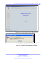
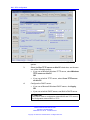
SIPN configuration
Navigation 107
Basic (simple) SIP DECT configuration with CS 1000 SIP Gateway
Configuration using IP DECT Configurator 108
DAP manager configuration 120
Configuration on Element manager 124
NRS configuration 133
Call server configuration 140
Branch Office configuration 143
Routed Head Quarter configuration 146
Configure Routed Head Quarter 147
Routed Head Quarter Configuration with Branch Office 148
Multi site mobility network configuration 150
Subscribe a multiple-site DECT handset 151
Import and export subscriptions 151
Configure NRS for multiple-site mobility network 152
Call server configuration to MSMN 153
Configuration of Personal Call Assistant 156
Configuration of UEXT on the remote system 157
107
107
SIPL configuration
Navigation 159
Basic (simple) SIP DECT configuration with CS 1000 SIP Line Gateway
Configuration using IP DECT Configurator 159
DAP manager configuration 173
SIP Line Gateway configuration 177
Call server configuration 177
Branch Office configuration 180
Routed Head Quarter configuration 182
Configure Routed Head Quarter 183
Routed Head Quarter Configuration with Branch Office 185
Multiple-site mobility network configuration 187
Subscribe a multi-site DECT handset 187
Import and export subscriptions 188
Personal Call Assistant configuration 189
Nortel Communication Server 1000
SIP DECT Fundamentals
NN43120-123 02.02 30 March 2010
Copyright © 2008-2010 Nortel Networks. All Rights Reserved.
159
159
5
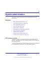
System administration
191
Navigation 191
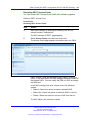
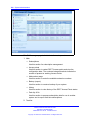
DAP manager overview 191
Subscription management 193
Subscribing a handset 193
Edit a subscription RPN 194
Disable a subscription 195
Removing a subscription 196
Deleting a number 196
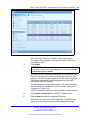
Use the filter 197
Handset status 198
DAP management 200
Changing a DAP Radio Part Number 200
Restarting a DAP 201
Restart all DAPs 201
Deleting a DAP 202
Add a DN range 202
Importing a DN range from a .csv file 203
System backup 205
Subscription export and import 205
Export subscriptions 205
Import subscriptions 208
DAP reboot history 208
System archive 209
Handset firmware update 210
Central directory access tool 214
Supported database types 215
Installation 216
Configure SIP DECT for Central directory access 217
System maintenance
Navigation 219
DAP Web interface 219
DAP LED indications 221
DAP firmware update 221
Remove and replace a DAP (if a new DAP is available) 223
Remove and replace a DAP (if a new DAP is not available) 224
System synchronization analysis 225
Synchronization Analyzer interface 226
Export and import SIP DECT system 233
Export a system 233
Import a system 234
DAP Controller deactivation 235
Nortel Communication Server 1000
SIP DECT Fundamentals
NN43120-123 02.02 30 March 2010
Copyright © 2008-2010 Nortel Networks. All Rights Reserved.
219
6
Uninstalling DAP Controller software 236
DAP Controller software update 237
Troubleshooting 238
If DAP is not working 238
If you cannot make calls from a DECT handset to an IP/TDM telephone on the
call server (SIPN Configuration) 239
If you cannot make calls between DECT handsets (SIPN Configuration) 240
If you cannot make calls to or from a DECT handset with SIPL
configuration 242
If you have problems 244
System survey 244
DAP information file 245
System archive 245
Network packet capture traces 246
Location builder tool
247
Use the Location builder tool 247
Create a location file 249
Maintenance 254
Site survey example
257
Site planning example: Able-Studio 257
The facts for Able-Studio 257
The site survey for Able-Studio 257
Deployment tool
263
Prepare the tool for deployment 264
Charging the deployment tool battery 265
Charging the deployment handset battery 266
Assembling the deployment tool 267
Testing the deployment handset 270
How the deployment tool works 271
Using the deployment tool 272
Handset tones interpretation 273
Rules for outdoor deployment 273
External housing installation
275
Installing a C4710 basestation in an external housing 275
Installing a C4710E basestation in an external housing with an external
antenna 278
Mounting the cabinet on a wall 280
Mounting the cabinet on a pole 281
Third Party Software
SRTP 283
TLS 284
Nortel Communication Server 1000
SIP DECT Fundamentals
NN43120-123 02.02 30 March 2010
Copyright © 2008-2010 Nortel Networks. All Rights Reserved.
283
7
.
New in this release
The following section details what is new in SIP DECT Fundamentals
(NN43120-123).
Features
This document is updated to document SIP DECT on SIP LINE.
Other changes
This section describes the detailed history of past releases of this
document.
Revision History
Date
Description
March 2010
Standard 02.02. This document is up-issued with information
for SIP DECT on SIP LINE, and to support Communication
Server 1000 (CS 1000) Release 6.0.
October 2009
Standard 02.01. This document is up-issued to reflect changes
in technical content stemming from SIP DECT 4.2, and to
support CS 1000 Release 6.0.
January 2009
Standard 01.07. This document is up-issued for CS 1000
Release 5.5 with editorial changes.
December
2008
Standard 01.06. This document is up-issued for CS 1000
Release 5.5, in response to change requests for content related
to SIP DECT 4.1.
July 2008
Standard 01.05. This document is up-issued in response to
change requests.
July 2008
Standard 01.04. This document is up-issued in response to
change requests.
Nortel Communication Server 1000
SIP DECT Fundamentals
NN43120-123 02.02 30 March 2010
Copyright © 2008-2010 Nortel Networks. All Rights Reserved.
8 New in this release
Date
Description
May 2008
Standard 01.03. This document is up-issued in response to
change requests.
March 2008
Standard 01.02. This document is up-issued in response to
change requests.
February
2008
Standard 01.01. This is a new document issued to support
CS 1000 Release 5.5. Some of the information in this new
document was previously contained in the following document:
DECT Fundamentals (NN43120-114).
Nortel Communication Server 1000
SIP DECT Fundamentals
NN43120-123 02.02 30 March 2010
Copyright © 2008-2010 Nortel Networks. All Rights Reserved.
9
.
Product overview
This section describes the capabilities, configuration, and design of SIP
DECT.
Navigation
•
“Overview of SIP DECT” (page 9)
Overview of SIP DECT
You can use Nortel Session Initiation Protocol (SIP) Digital Enhanced
Cordless Telecommunications (DECT) to move without restriction about
your work site while conducting telephone conversations, using wireless
handsets. The Nortel SIP DECT system includes one or more DECT
access points (DAPs or basestations) connected to the TLAN.
The system supports the following connection types for SIP DECT
configuration:
•
•
SIPL configuration, which uses SIP Line Gateway
SIPN configuration, which uses the Signaling Server
ATTENTION
This document describes both SIPN and SIPL connection types. Some sections
of this document discuss only SIPN or SIPL, while other sections cover
both, and contain notes concerning the differences between SIPN and SIPL
configuration. When you configure Nortel SIP DECT, ensure that you follow the
procedures for the configuration type that you require.
•
SIPL connections are available on CS 1000 Release 6.0 and later, and use
SIP Line Gateway nodes to connect SIP clients to the Call Server. SIPL
connections support SIP DECT handset registration, and require that you
create a SIPL subtype of UEXT blocks on the Call Server.
•
SIPN connections are available on CS 1000 Release 5.5 and later, and are
normally used only on that release. SIPN connections are based on SIP
trunks between SIP Gateway (Signaling Server) and NRS. SIPN connections
don’t support SIP DECT handset registration, and require that you create a
SIPN subtype of UEXT blocks on the Call Server.
Nortel Communication Server 1000
SIP DECT Fundamentals
NN43120-123 02.02 30 March 2010
Copyright © 2008-2010 Nortel Networks. All Rights Reserved.
10 Product overview
A minimal SIP DECT system has the following main components.
•
•
•
•
•
Call Server
SIP Line Gateway or Signaling Server (according to configuration type)
PC with DAP controller software installed
DAP
handset
Use the following tools to configure SIP DECT.
•
•
Element manager or overlay program for Call Server
•
•
IP DECT Configurator—used to enter SIP DECT configuration
Element manager and, if required, Network Routing Service (NRS)
manager for Signaling Server
DAP Manager (IP DECT Manager)—a Web interface used for SIP
DECT administration tasks such as adding a handset or removing a
subscription.
The IP DECT Configurator and the DAP manager IP DECT are available
as a part of the DAP controller software package.
The following software releases are required for the main system
components:
•
•
•
•
Call Server, Release 6.0
Signaling Server, Release 6.0
DAP software 4910b427.dwl or later
DAP controller 4.2 or later (PC software)
You can connect IP phones to the TLAN, and you can connect TDM
phones to the Call Server, Voice Gateway Media Cards, and other
required cards in Call Server. Use Voice Gateway Media Cards for
IP-to-TDM calls and for conference calls involving IP phones or DECT
handsets on basestations. The configuration can also include a PC with
DECT Messenger to provide the DECT messaging service on SIP DECT.
For SIP DECT to function properly on SIPN configurations, you must install
a dedicated Signalling Server running the SIP Gateway application. You
can use other applications, such as H.323 Gateway, NRS, and IP Phones,
on the same Signaling Server without limitations.
Use the Dynamic Host Control Protocol (DHCP) server or the Trivial File
Transfer Protocol (TFTP) server unless you use a DAP configuration
without DHCP or TFTP. You can configure the system to use two separate
Nortel Communication Server 1000
SIP DECT Fundamentals
NN43120-123 02.02 30 March 2010
Copyright © 2008-2010 Nortel Networks. All Rights Reserved.
Overview of SIP DECT
11
servers: one for DHCP and the other for TFTP. If the system requires
DAP configuration without DHCP or TFTP, the DHCP or TFTP server is
required during installation or configuration changes.
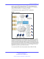
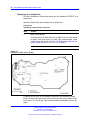
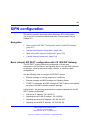
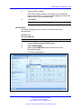
The following figure shows a general SIP DECT configuration.
Figure 1
SIP DECT configuration
You can install the DHCP or TFTP services, DECT Messenger, and DAP
controller on a single server or PC. However, you can also install them on
separate servers to enhance performance or facilitate administration. You
can also install Element Manager, NRS manager, and Telephony Manager
on the same server if the server has both a TLAN network interface and an
ELAN network interface. If the server you use cannot support all of these
applications, you can use more than one server.
You connect the DAP to the Communication Server 1000 (CS 1000)
Nortel Communication Server 1000
SIP DECT Fundamentals
NN43120-123 02.02 30 March 2010
Copyright © 2008-2010 Nortel Networks. All Rights Reserved.
12 Product overview
•
in SIPN configuration using the SIP trunks that you configure between
the Signaling Server and the NRS
•
in SIPL configuration using the SIP-line trunks that you configure for
SIP Line Gateway
Each DAP communicates with the subscribed DECT handsets in the
coverage area, and each DAP interacts with the CS 1000 and with other
configured DAPs in the company network.
You can run SIP DECT on the following configurations:
•
•
Communication Server 1000M or Communication 1000E
Signaling Server running SIP Gateway (SIPN only) or Signalling Server
running SIP Line Gateway
Use the SIP Redirect Server or SIP Proxy Server to perform the
appropriate NRS configuration for SIP DECT (SIPN connection type):
•
You can run SIP Redirect Server on Internet Server Platform (ISP)
1100s, Call Processor Pentium Mobile (CP PM) signaling servers,
or on IBM or HP Commercial-off-the-shelf (COTS) servers under
VxWorks.
•
You can run SIP Proxy Server on IBM or HP COTS servers under
Linux. You can run SIP Redirect Server on the same Signaling Server
as SIP Gateway dedicated to SIP DECT.
•
You can run SIP Redirect Server on a stand-alone Signaling Server.
If you install SIP Proxy Server you must use a stand-alone COTS server.
You cannot run SIP Gateway on the same server as the SIP Proxy Server.
Universal extension support
DECT handsets subscribed on DAPs are external to CS 1000. The CS
1000 does not control the state of DECT handsets. Therefore, the CS
1000
•
•
•
•
cannot detect individual key presses on DECT handsets
cannot control cadences on DECT handsets
cannot detect if a DECT handset is switched off and on
cannot control the handset display content
A DECT handset subscribed on a DAP cannot use the same range of
features available to analog, digital, or UNIStim IP phones on the CS 1000.
The Universal Extension (UEXT) feature on the Call Server provides
Configuration and status information for subscribed DECT handsets.
Nortel Communication Server 1000
SIP DECT Fundamentals
NN43120-123 02.02 30 March 2010
Copyright © 2008-2010 Nortel Networks. All Rights Reserved.
Overview of SIP DECT
13
No Associated Telephone (AST) or Computer-Telephone Integration (CTI)
capabilities are currently available for SIP DECT.
Each DECT handset has a local Directory Number (DN) in CS 1000. Use
this local DN to subscribe the corresponding DECT handsets on the SIP
DECT system through DAP Manager. DAP manager is available on the
server where you installed the DAP controller.
Configure the UEXT associated with a DECT handset as follows:
•
For the Primary DN of the UEXT (key 0 SCR), enter the local DN
associated with the DECT handset.
•
On SIPN configurations, for the Target DN of the UEXT (key 1 HOT P),
enter the digits required to access the SIP route (SIP Trunks)
configured to access DAPs plus the local DN of the handsets. This
consists of one of the following values:
— For access based on the configured Coordinated Dialing Plan
(CDP), compose the Target DN as follows:
<TSC>+<LOCAL DN>.
— For access based on the configured Uniform Dialing Plan (UDP),
compose the Target DN as follows:
<AC1 or AC2>+<LOC>+<LOCAL DN>.
•
For SIPL configuration for the Target DN of the UEXT (key 1 HOT U),
enter the digits of the User agent prefix (SIP Line configuration item)
plus the local DN of the handsets.
A UEXT corresponding to a DECT handset on the SIP DECT system
reflects the idle or busy status of the associated handset by a check for a
call processed between the handset and a DAP.
The Integrated SIP DECT provides the following UEXT features.
•
•
Make and receive simple calls
•
•
•
Consultative or Announced Call Transfer
•
•
Start a three-way call (SIPL configurations only)
Call Hold. Only one active call and one call on hold can exist for a
handset
Blind Call Transfer
Conference call participation if another party adds the DECT handset
to the conference
Calling Line ID (CLID) and Calling Party Name Display (CPND) for
simple calls not involving call transfer
Nortel Communication Server 1000
SIP DECT Fundamentals
NN43120-123 02.02 30 March 2010
Copyright © 2008-2010 Nortel Networks. All Rights Reserved.
14 Product overview
•
CLID and CPND for an internal line (digital or IP phone with display)
calling to or receiving a call from a DECT handset
•
Sending DTMF tones through the established connection to interact
with the called line (party), for example, to work with CallPilot
•
Support for a voice mailbox on CallPilot and Message Waiting
Indication (MWI)
•
•
•
•
•
•
Call Forward No Answer
Call Forward By Time of Day
Call Forward Busy
Hunting
Call Restrictions applicable to a UEXT
Twinned configuration (typically a desk phone plus a DECT handset)
DECT handset features
The user of a DECT handset subscribed on SIP DECT can perform the
following actions:
•
•
Make calls to DNs except restricted or blocked DNs.
•
Place the active call on hold by pressing the R key on the handset.
Return to the held call by pressing the R key. If a call is on hold,
another call can be made from the handset. After the second call is
established, the user can switch between the two calls with the R key.
•
Transfer a call to another DN
Receive and answer calls from the Call Server. If CPND is available,
the name of the caller and DN appear on the handset display. The
position and appearance of the name DN on the display depend on the
firmware installed on the handset.
— To perform a Blind Transfer
Place the current call on hold, call the required DN and immediately
release from the call.
— To perform a Consultative Transfer
Place the current call on hold, call the required DN, wait for the
answer and release the call after the DN answers.
•
Press digit keys on the handset during an established call to transmit
DTMF tones to the other party on the call.
•
For SIPL configurations only, you can initiate a three-way call. Place
an active call on hold, call the third party and wait until the call is
answered. Press the star (*) key to start the conference.
Nortel Communication Server 1000
SIP DECT Fundamentals
NN43120-123 02.02 30 March 2010
Copyright © 2008-2010 Nortel Networks. All Rights Reserved.
Overview of SIP DECT
15
If your system uses SIPN, you cannot use a DECT handset to configure
Call Forward or Hunting or to configure Call Restrictions. If the system
uses a twinned configuration, you can use the twinned desk phone to
configure Call Forward for the Primary DN with the existing keys or with
Flexible Feature Codes (FFC).
On SIPL configurations, you can activate FFC features such as Call
Forward, Make Set Busy, Ring Again, Call Park, which are available for
SIP Line users.
CallPilot and Message Waiting Indication support
DECT handsets subscribed on SIP DECT can use CallPilot.
You can configure Call Forward No Answer for the Primary DN of the
UEXT so that the unanswered calls on the corresponding DECT handset
or IP phone (in the case of a twinned configuration) are forwarded to
CallPilot. Calls can also be forwarded to CallPilot as busy treatment for
the Primary DN.
A user can call the CallPilot system from a DECT handset and log on to
the voice mailbox with the corresponding DN and password. The user can
then use the voice menus of the system as usual.
The system can send MWI to the DECT handset through the SIP Trunk.
If your system uses SIPL, enter the MWI primary DN of the SIP DECT
user. For SIPN configurations, configure additional DNs (to which CallPilot
sends MWI) for the voice mailbox corresponding to the UEXT Primary DN.
The additional DN configured in CallPilot is the external DN of the DECT
handset, which is the Target DN on the UEXT corresponding to the DECT
handset.
CS 1000 supports only the Unsolicited MWI NOTIFY model. An external
SIP UA cannot SUBSCRIBE to MWI NOTIFY messages and cannot
request the current status of MWI for the DN from the system (by sending
SUBSCRIBE messages). Instead, a SIP UA must be ready to receive MWI
NOTIFY messages from the system even if it did not SUBSCRIBE, and it
must update MWI according to those messages only.
For SIPN configurations, due to the Unsolicited MWI NOTIFY model used
in SIPN, the DECT handset relies on the MWI notifications sent by CS
1000. Therefore, the MWI based on the existing mechanism can be in the
incorrect state on the DECT handset if the handset was turned off and
on. The MWI can be in the incorrect state if the handset leaves and then
reenters the coverage area of the SIP DECT. In this situation, the MWI on
the DECT handset returns to the correct state when the next MWI state
change occurs in the CallPilot system.
Nortel Communication Server 1000
SIP DECT Fundamentals
NN43120-123 02.02 30 March 2010
Copyright © 2008-2010 Nortel Networks. All Rights Reserved.
16 Product overview
If you use a twinned configuration for a DECT handset, the corresponding
IP or TDM phone correctly reflects the current state of MWI, if it receives
MWI notifications for the Primary DN from CallPilot.
SIP DECT capacity limitations
The following capacity limitations apply to SIP DECT:
•
•
a maximum of 12 simultaneous calls for each DAP
•
a maximum of 6000 DECT handsets on each SIP DECT system
(potentially, several isolated SIP DECT systems can connect to CS
1000)
•
•
a maximum of 1000 simultaneous calls on each network
a maximum of 256 DAPs on each network (where handover and
synchronization between DAPs is possible)
a maximum of 25 subscription records for each DAP
If the planned number of DECT handsets in a SIP DECT system is
equal to M, and the number of DAPs in that system is equal to N, M
must be less than or equal to N*25.
Consider the following additional capacity limitations based on the CS
1000 configuration characteristics.
•
The number of available UEXTs is limited by the number of available
virtual Telephone Numbers (TN) in the system.
•
The number of DNs available for DECT handsets depends on the
configured dialing plan and the availability of the Directory Number
Expansion (DNXP) package (150).
Nortel Communication Server 1000
SIP DECT Fundamentals
NN43120-123 02.02 30 March 2010
Copyright © 2008-2010 Nortel Networks. All Rights Reserved.
17
.
Site planning and hardware
deployment
Navigation
• “Components of SIP DECT systems” (page 17)
• “Deployment requirements” (page 18)
• "Types of SIP DECT configuration" (page 28)
• “Site planning” (page 32)
• “System deployment” (page 38)
Components of SIP DECT systems
This section contains information about the following topics.
•
•
•
“Call server, Signaling server, and SIP Line Gateway” (page 17)
“PC (DAP controller)” (page 18)
“DECT Access Points” (page 18)
Call server, Signaling server, and SIP Line Gateway
Before you install SIP DECT you must install and configure a CS 1000
system, as follows:
•
•
For SIPN configuration, install Call Server and Signaling Server.
For SIPL configuration, install Call Server and SIP Line Gateway.
For more information about SIP Line Gateway, see SIP Line Fundamentals
(NN43001-508).
CS 1000 Release 6.0 introduces the CP PM Co-resident Call Server
and Signaling Server (CP PM Co-res CS and SS), which can run the
Call Server software, the Signaling Server software, and the System
Management software on the same hardware platform operating under
the RedHat Linux operating system.
Nortel Communication Server 1000
SIP DECT Fundamentals
NN43120-123 02.02 30 March 2010
Copyright © 2008-2010 Nortel Networks. All Rights Reserved.
18 Site planning and hardware deployment
For more information about CS 1000 installation, see Communication
Server 1000E Installation and Commissioning (NN43041-310).
PC (DAP controller)
Minimum specifications for the DAP controller PC are as follows.
•
•
•
•
2.4 GHz CPU
512 MB RAM
CD-ROM drive
1GB free hard disk space
DECT Access Points
Two models of DECT Access Points (DAP) are currently available for
Nortel SIP DECT: C4710 and C4710E. The C4710E is a special version
of the C4710 Access Point that provides an alternative with an external
antenna connection for outdoor use.
•
C4710 DAP
— PEC: NTCW26AAE5
— CPC: N0162007
•
C4710E DAP
— PEC: NTCW26BAE5
— CPC: N0162008
ATTENTION
The only audio codec supported on the C4710 and C4710E DAPs is the G.711
codec. Ensure that the G.711 codec is available in your system.
It is not possible to make calls between the Nortel IP Softphone 2050 and DECT
handsets when you select the I use a modem to connect to the network
check box in the Audio settings for the softphone. If you select this setting, the
Nortel IP Softphone 2050 uses the G.729 codec for all calls.
When using Multimedia PC Client, ensure that you select Medium Speed or
High Speed in the Multimedia PC Client Connection preferences if you plan to
make calls between DECT handsets and Multimedia PC Clients.
Ensure that the DAPs are installed according to the location
recommendations. For more information, see “Deployment requirements”
(page 18).
Deployment requirements
This section describes SIP DECT deployment requirements.
Nortel Communication Server 1000
SIP DECT Fundamentals
NN43120-123 02.02 30 March 2010
Copyright © 2008-2010 Nortel Networks. All Rights Reserved.
Deployment requirements
19
Navigation
•
•
•
“Radio synchronization” (page 19)
“IP network configuration” (page 23)
“Location requirements” (page 26)
Radio synchronization
The radio network structure supports seamless handover of existing calls.
This means that, during a call, if a handset moves from the coverage area
of one DAP into the coverage area of another DAP, the new DAP can
take over the call. The call is not interrupted, and the user is not aware of
the handover. In the traditional DECT system, synchronization between
DAPs occurs over the wired network. SIP DECT requires an accurate
synchronization of the radio signals in the air to support handover.
ATTENTION
If a DAP cannot receive synchronization signals from at least one other DAP, it
operates in a single cell mode and cannot handover to other DAPs or receive
handover from them.
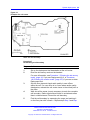
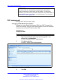
Represent each DAP cell as a circle indicating the radio signals around
the DAP. Figure 2 "DAP radio signal synchronization" (page 20) shows
two circles around the DAP.
•
an inner circle in which sufficient radio signal strength exists for
acceptable voice quality
•
an outer circle in which sufficient signal strength exists for
synchronization, but not enough for acceptable voice quality
Nortel Communication Server 1000
SIP DECT Fundamentals
NN43120-123 02.02 30 March 2010
Copyright © 2008-2010 Nortel Networks. All Rights Reserved.
20 Site planning and hardware deployment
Figure 2
DAP radio signal synchronization
Due to the cellular structure of a DECT radio network, overlap exists in
the cells with sufficient voice quality. The wider cell limit around the DAP
therefore has some overlap with the other cell and reaches to the radio of
the other cell. Consequently, the DAPs of the overlapping cells exchange
radio signals. These radio signals are weak relative the signal needed by
the handsets, but are strong enough for synchronization.
ATTENTION
For signal strength calculation see “Signal strength and frame errors” (page 22).
If one DAP receives a signal from another, the receiving DAP checks the
radio signals on Primary Access Right Identity (PARI), to ensure that the
signals belong to the same DECT system. If the signals belong to the
same DECT system, the DAPs synchronize according to user-configured
rules.
Nortel Communication Server 1000
SIP DECT Fundamentals
NN43120-123 02.02 30 March 2010
Copyright © 2008-2010 Nortel Networks. All Rights Reserved.
Deployment requirements
21
ATTENTION
If two or more independent SIP DECT systems have overlapping coverage
areas, configure these systems so each has a unique subset or portion of
carriers. When each system has a unique subset of carriers, interference
between the systems is reduced.
Reducing the number of available carriers reduces the maximum number of
simultaneous calls in the DECT system. To achieve your desired call capacity,
you can be required to install extra DAPs. For more information, see step 4 of
Configuring DECT Settings.
The DAPs transmit with a minimum of two channels carrying primary voice
and data, also named bearers. If no voice calls occur over a DAP, the
DAP transmits two dummy bearers. If one or more voice calls occur on the
DAP, one is one a dummy bearer, while the others are voice calls.
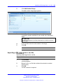
Synchronization hierarchy
If two or more DAPs belong to the same system, the DAPs automatically
synchronize using a hierarchical structure. In most cases synchronization
is automatic, but if your system has a complex DAP cell structure, you
must manually configure synchronization.
The DAP controller tracks the synchronization structure and assigns each
DAP a unique Radio Part Number (RPN) after the DAP starts the first time.
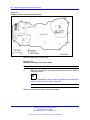
One or more DAPs act as a synchronization source to form the root of
the hierarchical structure, as illustrated in Figure 3 "DAP synchronization
hierarchy" (page 21).
Figure 3
DAP synchronization hierarchy
Nortel Communication Server 1000
SIP DECT Fundamentals
NN43120-123 02.02 30 March 2010
Copyright © 2008-2010 Nortel Networks. All Rights Reserved.
22 Site planning and hardware deployment
If more than one synchronization source is present, each one forms a
separate hierarchy of DAPs called a synchronization island.
Automatic synchronization occurs within each synchronization island using
the following rules.
•
After a DAP starts, it searches for existing DAPs. If it finds one with a
lower RPN, it synchronizes with it. If no other DAP exists with a lower
RPN, the new DAP becomes the synchronization source.
ATTENTION
Extra DAPs can be required to establish a synchronization path.
•
If a DAP detects more than one other DAP, it synchronizes with the
DAP with the shortest path to the synchronization master. If two or
more DAPs have the same path length separating them from the
master, the new DAP synchronizes to the DAP with the lowest RPN.
ATTENTION
After you install SIP DECT, wait at least 15 minutes until you see the results of
the automatic synchronization.
To make a DAP a synchronization master or to give a DAP a higher
position in the synchronization structure, you can manually assign a lower
RPN number to a DAP. You can manually assign RPNs using the DAP
Manager Web interface. Automatically assigned RPNs start at 010. If you
manually assign a new RPN, ensure that it is in the range 000 to 00F.
ATTENTION
You must determine the position of the Synchronization Master before you start
site planning. Place the synchronization master, which is the DAP with the
lowest RPN, in the middle of your site, building, or buildings.
Signal strength and frame errors
Signal strength is important for DAP-handset communication (voice quality)
and synchronization between DAPs. The following items are relevant for
the signal strength for synchronization.
•
To achieve a good voice quality, the minimum signal strength at the
receiver in the handset and DAP must be --72 Decibels (referenced to
milliwatts) (dBm). This includes a margin of --10 dBm for fast fading
dips.
•
Synchronization is possible if the strength of the received signal from
another DAP is --80 dBm to --85 dBm. This is adjustable.
•
In an open area, the distance is doubled if the received signal strength
is 6 dB lower. This means that at a minimum signal strength for good
voice quality of --72 dBm and a distance X, the signal strength at the
Nortel Communication Server 1000
SIP DECT Fundamentals
NN43120-123 02.02 30 March 2010
Copyright © 2008-2010 Nortel Networks. All Rights Reserved.
Deployment requirements
23
double distance, 2X, is --78 dBm. For more information, see Figure 4
"Signal strength considerations" (page 23).
Figure 4
Signal strength considerations
•
An open area has more than sufficient signal strength for
synchronization. The expected level at the double distance is --78
dBm. The required level is --80 dBm to --85 dBm. This leaves a safely
margin of 2 to 7 dB.
•
Obstructions between the DAPs can introduce loss. Also, many objects
cause reflections that let the signal reach the DAPs through other path
with sufficient signal strength.
•
In rare cases, factors in the surrounding environment can cause
the error rate in the received frames to be temporarily much higher
than is normal for speech. An occasionally elevated error rate does
not indicate a problem with your SIP DECT system. However, if you
consistently see a high error rate, then there is a problem with the
deployment of your SIP DECT system.
Frame errors
Frame errors rarely can occur in DECT. The number of frame errors for
each reading may not be more than four. The most common cause of
frame errors higher than four is a high number of reflections. This causes
an audible click during calls.
IP network configuration
The IP network must be able to support SIP DECT; this section provides
information about planning an IP network that is suitable for supporting
SIP DECT.
Nortel Communication Server 1000
SIP DECT Fundamentals
NN43120-123 02.02 30 March 2010
Copyright © 2008-2010 Nortel Networks. All Rights Reserved.
24 Site planning and hardware deployment
SIP DECT typically uses existing IP network infrastructure and facilities
for the network connection. For IP connectivity, you must configure the
network to ensure that all SIP DECT components have the following
characteristics:
•
•
•
are equipped with unique IP addresses (some static, some dynamic)
can reach all the required services
can be reached by all clients and counterparts
Ethernet requirements
The following items describe the Ethernet requirements.
•
The IP network must offer a Quality of Service (QoS) that is sufficient
to support the SIP DECT Voice over IP.
•
The IP network must support transparent IP multicast between all
DAPs and the DAP controller.
•
•
Connect only one DAP to one IP Switch port.
DAP supports full duplex and supports autonegotiation if DAP is
connected to a port on an Ethernet Switch.
ATTENTION
Configure the Ethernet switch ports to which the DAPs are connected to use
autonegotiation. If the switch does not support autonegotiation, you can use
full-duplex; however SIP DECT can operate incorrectly on some switches
when you configure them to use full-duplex.
•
Ensure that enough unique IP addresses are available to support both
data networking traffic and SIP DECT components. You can configure
private IP addresses for local traffic, and you can configure private IP
addresses on the local network to connect to public IP addresses if you
use Network Address Translation (NAT). However, SIP DECT does
not support NAT.
•
Ensure that IP addresses and routing are consistent with each other
to deliver the required transparency. Also ensure that IP addresses
are consistent with routing for normal unicast traffic as well as for the
required multicast traffic.
•
The maximum cable length between the DAP and IP network
equipment, such as a switch, is 100 meters for a Category 5,
unshielded twisted-pair, half-duplex cable. If the required cable length
between the IP network equipment and the DAP exceeds 100 meters,
use Long Range Ethernet equipment in the connection. Several
manufacturers offer such a solution, which allows cable lengths of
more than one kilometer (km).
Nortel Communication Server 1000
SIP DECT Fundamentals
NN43120-123 02.02 30 March 2010
Copyright © 2008-2010 Nortel Networks. All Rights Reserved.
Deployment requirements
25
Fixed IP network addresses
You must provision fixed IP addresses for the following servers:
•
The TFTP server stores the configuration file and the firmware that are
available to the DAPs. After a DAP starts up, the DHCP server sends
the DAP the IP address of the TFTP server. The DAP then downloads
the configuration files from the TFTP server. The TFTP server often
runs on the DAP controller or manager PC.
•
The DHCP server (optional) sends the address of the DNS server to
the DAP. The DAP does not support Domain Name Resolution.
•
The DAP controller or manager requires a fixed IP address. The DAPs
retrieve this fixed IP address from the configuration file that the DAP
loads from the TFTP server.
•
The IP address of the PABX is reachable either through a router or
directly.
The PABX is sometimes referred to as Gatekeeper or SIP proxy,
depending on the type of PABX that is used.
To facilitate network management, Nortel recommends that fixed IP
addresses are also assigned by the DHCP server. Ensure that the DHCP
server has the hardware MAC addresses of all servers to issue the proper
(fixed) IP addresses to each individual server.
The DAP IP address can be stored in flash memory. If the IP address is
stored, the DHCP server is needed only for the first startup. Then an IP
address is assigned to the DAP.
Dynamic IP network addresses
Network stations, which are not servers (PC workstations and DAPs), can
use dynamic IP addresses assigned by DHCP. For dynamic IP addresses,
you need not specify the MAC addresses of all the network stations in the
DHCP server.
Ensure that you configure the DHCP server to assign IP addresses from
a specific range to unknown MAC addresses. However, unknown LAN
stations have valid IP addresses, which can be a minor network security
issue. To solve this, use the Vendor Class Identification (VCI) in the DHCP
server. The DHCP server issues IP addresses only to devices that have
the DAP VCI. Ensure that the DHCP server can make a distinction in VCIs.
The DAP VCI is D(ECT)AP 49.
ATTENTION
For SIPN configurations, ensure that a static IP address is issued to the DAP
selected as the DAP Redirect Server. For more information, see “Adding
Gateway Endpoint for DAP redirect server” (page 136).
Nortel Communication Server 1000
SIP DECT Fundamentals
NN43120-123 02.02 30 March 2010
Copyright © 2008-2010 Nortel Networks. All Rights Reserved.
26 Site planning and hardware deployment
Each DAP in a SIP DECT system is assigned a dynamic IP addresses by
the DHCP server. You can configure the DAPs to store the IP address
in flash memory, so the DHCP server is required only during the initial
configuration of the system.
Multicast addresses
SIP DECT uses Multicast addresses for the following functions:
•
Communication between the SIP DECT network components to locate
or address a handset.
If a handset must be reached, the request must simultaneously go
to all DAPs. For example, if you use the page function during an
incoming call, a single multicast message is sent to all DAPs to find the
DAP for your handset quickly and efficiently.
•
Seamless handover from one DAP to the other
If inter-cell handover is necessary, the media path must be redirected
from the existing DAP to another DAP. The handset always initiates
a handover. The handset sends request to another DAP (not the
DAP with the current connection). This DAP issues a multicast on
the network to determine on which DAP the voice connection exists.
The DAP, with the existing voice connection, responds and then the
connection can be redirected from the DAP with the existing voice
connection to the new DAP.
•
Synchronization between DAPs
You must configure multicast before synchronization can occur
between DAPs in the SIP DECT system.
All network components must support forwarding of IP multicast packages.
The IP DECT Configurator proposes a default multicast IP address
(239.192.49.49). This is a multicast address in the private multicast IP
address range for use in private IP networks. If you are not sure you can
access this address, contact the local IT manager.
ATTENTION
You must disable IGMP Snooping and Spanning Tree Protocol on switch ports
where SIP DECT equipment is connected.
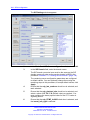
Location requirements
Comply with the following requirements for DAP location:
•
•
Ensure that the location complies with local electrical codes.
•
Install DAPs in a vertical position. The radiation pattern differs between
the horizontal and vertical positions.
Install DAPs indoors where no condensation occurs and the
temperature remains within the range of 0C to 40C.
Nortel Communication Server 1000
SIP DECT Fundamentals
NN43120-123 02.02 30 March 2010
Copyright © 2008-2010 Nortel Networks. All Rights Reserved.
Deployment requirements
27
•
•
•
Do not mount a DAP to a metal surface.
•
Position DAPs at least 1 meter (m) from large concrete or stone
columns and from major building structural members such as support
beams or columns.
•
Position the DAPs high enough to clear obstructions between the
DAPs and the cell edge close to the ceiling.
•
Mount the DAPs clear of obstacles such as pipes or ducts.
Do not roll up the extra cabling behind a DAP.
Position DAPs upright on walls. DAPs must be at least 30 cm from the
ceiling.
To install the DAPs outdoors, see “External housing installation” (page
275).
DAP power configuration
DAPs are powered using one of the following methods:
•
Locally using an RJ-11 connector. The AC voltage must be 40V (+ or
--10 percent). Use an AC adaptor that provides at least 10 Watts. For
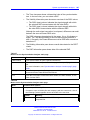
part numbers of available AC adaptors, see Table 1 "Part numbers"
(page 27).
Table 1
Part numbers
•
NTCW28AAE5
N0162030
DAP AC/AC adaptor Eur
NTCW28BAE5
N0162032
DAP AC/AC adaptor UK
NTCW28CAE5
N0162033
DAP AC/AC adaptor ANZ
Through Power over Ethernet (PoE) as defined by IEEE802.3af
specifications. The DAPs support both phantom power and power over
spare wires. The following specifications apply to PoE power.
— Minimum 36 Volts and maximum 60 Volts of voltage at the DAP
— Standard RJ-45 connector, using the spare wires pins (wires)
— Maximum cable length of 100 meters
Both phantom power and power over spare wires are provisioned on the
same DAP to provide system redundancy. The power input providing the
highest voltage is active. If one power input fails, the other takes over
without service interruption.
Nortel Communication Server 1000
SIP DECT Fundamentals
NN43120-123 02.02 30 March 2010
Copyright © 2008-2010 Nortel Networks. All Rights Reserved.
28 Site planning and hardware deployment
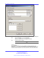
Types of SIP DECT configuration
You can implement SIP DECT in various system configurations to
accommodate your needs. The most common SIP DECT configurations
are as follows:
•
•
•
•
•
Basic (or Simple) Configuration
•
Basic (or Simple) Configuration
Routed Head Quarter Configuration
Branch Office Configuration
Routed Head Quarter Configuration with Branch Office
Multi Site Mobility Network Configuration
In Basic Configuration all DAPs are in the same subnet that is
based on one or more IP switches. IP multicast must be able to
occur between all DAPs. The configuration supports seamless
handover between all DAPs. For an illustration of a simple SIP DECT
configuration, see Figure 5 "Simple SIP DECT network configuration"
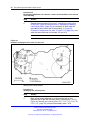
(page 28).
Figure 5
Simple SIP DECT network configuration
•
Routed Head Quarter configuration
Routed Head Quarter Configuration is used for a Large Campus
network that is split into several subnets. In this configuration DAPs
belong to various subnets and behave as one large SIP DECT system
with the full support of seamless handover. IP multicast must be able
to occur between all DAPs in the Campus network, through IP switches
and the IP routers that connect the various subnets. For an illustration
Nortel Communication Server 1000
SIP DECT Fundamentals
NN43120-123 02.02 30 March 2010
Copyright © 2008-2010 Nortel Networks. All Rights Reserved.
Types of SIP DECT configuration
29
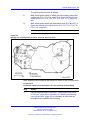
of a Routed Head Quarter configuration, see Figure 6 "SIP DECT
configuration Routed Head Quarter" (page 29).
Figure 6
SIP DECT configuration Routed Head Quarter
In Routed Head Quarter Configuration network settings must comply
with the following requirements:
— The network must support Quality of Service (QoS) and IP
connectivity throughout the Campus.
— Routers must support IP multicast routing.
— The IP multicast address for SIP DECT must be the same in all
subnets.
— Multicast Time to live (TTL) must be greater than 1.
— In the SIP DECT configuration, you must use an “aggregated”
subnet mask that covers all the subnets where DAPs are present.
For instance, if each subnet is defined by mask 255.255.255.0,
then “aggregated” mask 255.255.248.0 covers up to four such
subnets.
•
Branch Office Configuration
Nortel Communication Server 1000
SIP DECT Fundamentals
NN43120-123 02.02 30 March 2010
Copyright © 2008-2010 Nortel Networks. All Rights Reserved.
30 Site planning and hardware deployment
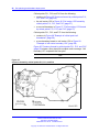
Branch Office Configuration is used for a Large Campus network
that is split into various (geographical) segments (branch offices). IP
multicast must be able to occur between all DAPs in every branch
office and no IP multicast is allowed between any two branch offices.
In this configuration, each branch office behaves as an isolated site
of a large SIP DECT system. Branch Office configuration supports
seamless handover within each isolated site (branch office), but not
between sites. Support is unavailable for roaming between branch
offices. For an illustration of a Branch Office Configuration, see Figure
7 "Branch Office Configuration" (page 30).
Figure 7
Branch Office Configuration
For Branch Office Configuration, network settings must comply with
the following requirements:
— The network between Branch Offices and Call Server must support
QoS.
— Branch Offices must be in separate subnets (IP router(s) needed).
— DAPs in various Branch Offices must be located so that no
synchronization can occur between any two DAPs belonging to
various Branch Offices.
— Routers must block IP multicast between Branch Offices (multicast
TTL = 1, which means that IP multicast packets do not cross IP
routers).
Nortel Communication Server 1000
SIP DECT Fundamentals
NN43120-123 02.02 30 March 2010
Copyright © 2008-2010 Nortel Networks. All Rights Reserved.
Types of SIP DECT configuration
•
31
Routed Head Quarter Configuration with Branch Office
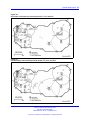
Routed Head Quarter Configuration with Branch Office makes it
possible to create a Routed Head Quarter Configuration in one (and
only one) the branch office. Within the Branch Office with Routed Head
Quarter, DAPs belong to various subnets and behave as a single site
of one SIP DECT system with the full support of seamless handover.
As for the whole SIP DECT system, each Branch Office (including the
Branch Office with Routed Head Quarter) behaves as isolated site of
that SIP DECT system. Branch Office configuration supports seamless
handover within each isolated site (branch office), but not between
sites. Support is unavailable for roaming between branch offices.
Figure 8
Routed Head Quarter Configuration with Branch Office
In Routed Head Quarter Configuration with Branch Office the network
settings must comply with the requirements for Routed Head Quarter
configuration (for the network settings within Routed Head Quarter)
and with the requirements for Branch Office configurations (for the
network settings between Branch Offices, including the Branch Office
with Routed Head Quarter).
•
Multi Site Mobility Network Configuration
Multi Site Mobility Network (MSMN) Configuration makes it possible
to use portable DECT handsets on various MCDN nodes where each
node is a CS 1000 system plus the corresponding SIP DECT system.
MSMN allows roaming between independent SIP DECT systems
installed on separate Call Servers (connected by trunks). Handover
between independent SIP DECT systems is not possible.
Nortel Communication Server 1000
SIP DECT Fundamentals
NN43120-123 02.02 30 March 2010
Copyright © 2008-2010 Nortel Networks. All Rights Reserved.
32 Site planning and hardware deployment
A SIP DECT system on an individual MCDN node can be any of the
previously described configurations: Basic (Simple), Routed Head
Quarter, Branch Office, or Routed Head Quarter with Branch Office.
Site planning
Site planning is an information gathering process that begins with a site
survey and ends with deploying SIP DECT. The information received in the
site survey determines customer requirements and the number of cells
required to support traffic.
You can use the Location builder tool (a part of the DAP controller
software package) to plan your site. For more information, see “Location
builder tool” (page 247).
Site survey
•
Site maps
Site maps are an essential requirement in advance of a survey. A
map of the complete site (if more than one building) and plans of each
floor of each building are required. Make sure that dimensions are
clearly stated on the maps. Additional information such as the use of
buildings (office, hotel, factory, store), construction materials (walls,
floors, ceilings), and cabling infrastructure are helpful in estimating
DAP positions in advance.
•
Number of users (handsets)
Number of users (handsets), both initial and foreseeable growth, and
areas of above average and below average traffic density.
•
Allowed and prohibited DAP positions
A customer can prohibit the installation of DAPs in certain areas, or
require that DAPs be installed out of sight.
•
Details of required coverage
Determine to what areas coverage must extend; for example:
elevators, stairwells, toilets, outdoor areas.
•
Position of the DECT System and available cabling
Ensure that you can use existing cabling for the connection between
the DECT System, and that the DAP cables meet or exceed the UTP
Cat 5 standard. If the type and quality of the available cabling is not
sufficient for the connection and limits the maximum distance between
the DAP and DECT System, you may require new cabling.
•
Sensitive electronic equipment
Check whether sensitive electronic equipment is present, for example,
laboratory or medical equipment. Although the transmitted power of
Nortel Communication Server 1000
SIP DECT Fundamentals
NN43120-123 02.02 30 March 2010
Copyright © 2008-2010 Nortel Networks. All Rights Reserved.
Site planning
33
the DAPs is low (about 250 mW), it can interfere with some sensitive
electronic equipment.
•
Traffic information
Gather information about user density, amount of traffic, and whether
redundancy is required. You require this information to determine the
number of DAPs that are required and therefore the required cabling.
A DAP must always have at least one channel free to allow handover
(either intracell or intercell handover). Make sure that the maximum
expected traffic density is not more than 11 channels simultaneously.
For more information, see “Site survey example” (page 257).
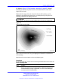
Speech quality
A relationship always exists between coverage and speech quality.
The greater the distance between the handset and the DAP, the lower
the quality. Therefore, you must understand the relationship between
the coverage and the expected voice quality. For an illustration of the
relationship between coverage and voice quality in an open environment,
see Figure 9 "Coverage and speech quality in an open environment."
(page 33).
Figure 9
Coverage and speech quality in an open environment.
Be aware that DECT is a digital communication system. It incorporates a
“transmission errors hiding” system. This means that it tries to hide the
transmission errors. The results of this mechanism are as follows:
Nortel Communication Server 1000
SIP DECT Fundamentals
NN43120-123 02.02 30 March 2010
Copyright © 2008-2010 Nortel Networks. All Rights Reserved.
34 Site planning and hardware deployment
•
•
•
A small incidental transmission error is not noticeable in speech.
A minor transmission error causes audible clicks during speech.
A major transmission error causes the loss of speech.
The following factors effects the voice quality as well:
•
Moving speed
The DECT techniques allow a maximum moving speed of 5 kilometers
per hour (km/h). Bear this in mind if your DECT system must cover an
elevator.
•
Metal Construction
In metal structures, reflection can negatively impact voice quality (clicks
and interruptions can occur) even if you are close to the DAP. This
effect is made worse when the handset is in motion.
For more information see “Coverage calculation” (page 35).
The required quality depends on the customer requirements and the
environment. The following are the various quality levels:
•
Excellent and good
In business, office, and first aid environments, the excellent and good
voice quality is required to avoid dropped calls, inherent sounds, or
pauses in important conversations. Any sounds produced by a lower
quality level noticed by the system users, because these environments
are usually quiet or produce less background noise.
•
Satisfactory
In less critical areas like basements, stock rooms, and cold stores, the
satisfactory quality level is usually accepted because they are noisy
environments. In a noisy environment people do not notice an audible
click in a conversation, because the environment produces a lot of
background noise. This environmental background noise may also
contain audible clicks. Sometimes, the voice of a user is less audible to
the other user listening at the other end of the conversation because
of the background noise.
Use the following points as general guidelines:
•
A maximum of 20 percent of the whole coverage is considered as
satisfactory.
•
Install a hard-wired emergency telephone in those areas where the
quality is satisfactory. This ensures that people can always make a call
in case of an emergency.
•
If you agree with the customer on lower speech quality, then make
sure that this is well documented and signed by the customer. If
Nortel Communication Server 1000
SIP DECT Fundamentals
NN43120-123 02.02 30 March 2010
Copyright © 2008-2010 Nortel Networks. All Rights Reserved.
Site planning
35
the customer becomes dissatisfied afterwards, you can refer to the
agreement. Also, be aware that, if the speech quality is low in certain
areas, the customer may perceive that you delivered a low-quality
system.
•
If a lower voice quality level is acceptable, ensure that all calls are
received and dropped calls are avoided.
Coverage calculation
The coverage can be calculated in advance, before executing a site
survey. Calculation is based on the following theory.
The transmission path between the DAP and the handset is subject to
radio-propagation related peculiarities, such as:
•
•
•
Dynamically changing environment
Signal attenuation due to fixed and moving objects
Multi-path propagation of the signal
The signal from the transmitter is attenuated in the link before it arrives
at the receiver. The link consists of a transmission path through the air
and through obstacles such as walls. The air and the obstacles cause
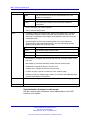
attenuation called insertion loss. The following table shows typical insertion
losses for some obstacles.
Table 2
Typical insertion losses of some obstacles
Material
Insertion loss (dB)
Glass
2
Glass, metal reinforced grid
10
Glass, metal clad sunguard
10
Wall, indoor, plaster, wood
2
Wall, brick, 10 cm
3.5
Wall concrete, 10 cm
6
Wall concrete, 15 cm
9
Wall concrete, 20 cm, large windows
6
Wall concrete, 40 cm
17
Ceiling, concrete, reinforced, tiles
17-20
With the DECT equipment, the available link budget is 38 dB. This is the
maximum allowed loss in the link, under constraints of excellent and good
speech quality and the ability for the user to move.
Nortel Communication Server 1000
SIP DECT Fundamentals
NN43120-123 02.02 30 March 2010
Copyright © 2008-2010 Nortel Networks. All Rights Reserved.
36 Site planning and hardware deployment
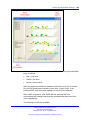
To calculate the distance between DAP and handset, use the information
in Figure 10 "DECT range calculation chart" (page 36).
Using the building map, start at the possible DAP location. Move away
from the DAP location. Calculate the distance. When you encounter
an obstacle, calculate the insertion loss. Using the chart below, start
in the lower left corner (0,0), move horizontally, to the value for the
actual distance. Move vertically to the value for the insertion loss of
the encountered obstacle. If the curve in the chart is crossed, read the
maximum distance for that specific DAP in that situation. This gives the
cell size in that specific direction. Ensure that outside the calculated
range communication is possible but a good voice quality is no longer
guaranteed.
Figure 10
DECT range calculation chart
Nortel Communication Server 1000
SIP DECT Fundamentals
NN43120-123 02.02 30 March 2010
Copyright © 2008-2010 Nortel Networks. All Rights Reserved.
Site planning
37
The range in the air is 80 m from the DAP, for optimal communication
quality. The result of this coverage calculation is a map with possible DAP
positions indicated.
Use the following DAP ranges as a rough guide for planning the DAP
positions:
•
•
•
In the line of sights the DAP has a range of approximately 80 m.
In halls the DAP has a range less than 80 m.
In buildings the DAP has a range of 15 to 40 m. This is based on the
assumption that walls are made of light brick, plasterboard or wallboard
with metal frames. Normal electrical wiring, central heating pipes, office
furniture and desktop computer equipment have no significant effect.
Ensure that you consider the signal shadowing effect of stairways, lift
shafts, and shielded rooms.
The following items cause shadowing of the radio signal:
•
•
Thick walls, especially cavity walls and reinforced concrete walls.
•
•
•
•
Steel doors, partitions, or walls.
Windows or glass in doors with steel wire reinforcement or metallic
reflection film.
Fire resistant doors.
A wall of steel cabinets, large computer equipment or machinery.
Thick concrete floors.
During the site survey, be aware of the following:
•
Choose a corridor or other large open space rather than an enclosed
area so that the radio signal passes through as few walls as possible
to reach as large an area as possible.
•
Radio reception inside a vehicle is poor unless the user is close to the
DAP.
•
Ensure that the DAP is placed high enough to be unaffected by
surrounding objects. For example, a DAP in a car park needs to be
placed higher than a vehicle that is parked next to it.
•
•
Ensure that DAPs are separated by at least 1 meter.
The presence of another unsynchronised DECT System, or any similar
system in adjacent buildings, causes interference.
Nortel Communication Server 1000
SIP DECT Fundamentals
NN43120-123 02.02 30 March 2010
Copyright © 2008-2010 Nortel Networks. All Rights Reserved.
38 Site planning and hardware deployment
•
A DAP or a handset interferes with sensitive laboratory equipment
and medical equipment (for example, ensure that DAPs are installed
outside of an operating room at an hospital.)
•
Ensure that significant interference from unsuppressed engines or
electric motors is accounted for.
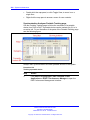
Traffic density calculations
Perform the traffic density calculations so that you have a low blocking
probability in the system.
For traffic calculations, you must know
•
•
the number of users
the type of users
The following table lists the three user types.
Table 3
Three user types
Traffic
Application
Erlang/User
Low
normal offices
0.05
Average
Executive and secretary
groups
0.1-0.15
High
help desks, Tele-services
0.2-0.25
The Erlang value for DAP C4710 and C4710E (12 radio channels), with
blocking probability of 0.5%, is 5.25.
Calculate the traffic density using the following formula:
One cell has 20 users: five average traffic and 15 low traffic. The load is:
(5 x 0.15) + (15 x 0.05) = 1.5 Erlang
Therefore, one 12 channel DAP is sufficient for this cell.
System deployment
This section describes the basics of SIP DECT system deployment.
DECT Deployment Kit 2
The DECT Deployment Tool (deployment tool) determines cell centers and
cell boundaries.
Nortel Communication Server 1000
SIP DECT Fundamentals
NN43120-123 02.02 30 March 2010
Copyright © 2008-2010 Nortel Networks. All Rights Reserved.
System deployment 39
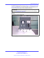
The DECT Deployment Kit 2 is shown in Figure 11 "Deployment Kit 2 and
carrying case" (page 39). For more information about the deployment kit,
see the DeTeWe User Manual that accompanies each kit.
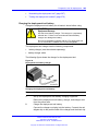
ATTENTION
If you use an older deployment tool that differs from the one in the following
figure , see “Deployment tool” (page 263).
Figure 11
Deployment Kit 2 and carrying case
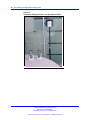
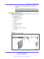
The following figures shows the assembled kit.
Nortel Communication Server 1000
SIP DECT Fundamentals
NN43120-123 02.02 30 March 2010
Copyright © 2008-2010 Nortel Networks. All Rights Reserved.
40 Site planning and hardware deployment
Figure 12
Assembled Deployment Kit 2 and DeTeWe handsets
Nortel Communication Server 1000
SIP DECT Fundamentals
NN43120-123 02.02 30 March 2010
Copyright © 2008-2010 Nortel Networks. All Rights Reserved.
System deployment 41
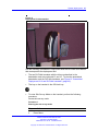
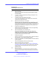
Figure 13
Deployment Kit 2 basestation
Use the following information in conjunction with the DeTeWe User Manual
that accompanies the deployment tool.
•
The two DeTeWe handsets with the kit are subscribed to the
basestation and are numbered 13 and 15. To view the assembled
basestation and the DeTeWe handsets, see Figure 12 "Assembled
Deployment Kit 2 and DeTeWe handsets" (page 40).
•
The key on the handset is the Off-Hook key.
•
To enter Site Survey Mode on the handset, perform the following
procedure.
Access site survey mode.
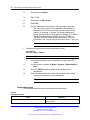
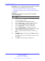
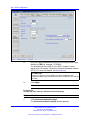
Procedure 1
Entering the site survey mode
Step
1
Action
Press Menu.
Nortel Communication Server 1000
SIP DECT Fundamentals
NN43120-123 02.02 30 March 2010
Copyright © 2008-2010 Nortel Networks. All Rights Reserved.
42 Site planning and hardware deployment
2
Scroll down to System
.
3
Dial ***76#.
4
Scroll down to Site Survey.
5
Press OK.
6
Use the handset to detect frame errors and signal strength.
The Frame Error value for the handset is the number of
detected Sync/ACRC errors within the last 100 receiving
frames, for example, 1 second. For proper deployment,
ensure the Frame Error value does not exceed 4. An Radio
Signal Strength Indication (RSSI) value of –80 dBm to
–85 dBm is used to indicate the cell boundary. For more
information, see “Signal strength and frame errors” (page 22).
--End--
•
Subscribe a handset that has de-subscribed in error.
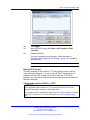
Procedure 2
Re-subscribing a handset
Step
1
Action
Long-press the button on the basestation to open the DECT
system.
2
On the handset, navigate to Menu > System > Subscription >
New.
3
Enter the PARK number provided at the bottom of the
basestation.
4
Enter the authorization code (the last four digits of the serial
number at the bottom of the basestation).
--End--
Deployment terms
The following table lists terms associated with deployment.
Table 4
Deployment terms
Term
Estimated number of handsets
Definition
The average number of handsets expected in a
particular cell.
Nortel Communication Server 1000
SIP DECT Fundamentals
NN43120-123 02.02 30 March 2010
Copyright © 2008-2010 Nortel Networks. All Rights Reserved.
System deployment 43
Table 4
Deployment terms (cont’d.)
Term
Definition
Cell
The coverage area provided by a basestation.
Cell boundary
The edge of a cell showing the cell coverage
area.
Cell center
The place where all the basestations are
installed.
DECT Radio Deployment Tool
The tool used to determine the radio range of a
basestation.
Critical point
A point or location defined as an outer corner of
a coverage area, or points that can be difficult
for the radio signal to reach.
Coverage area
The area defined by the customer in which a
handset user can expect to be able to make and
receive calls.
Link
If a handset and a basestation are in radio
communication with each other.
Range
The distance from a cell center to the cell
boundary.
Office
The location where a handset user spends the
majority of the day.
Traffic table
Traffic tables record site traffic information from
the floor plan and the customer. The traffic
table helps to determine the required number of
basestations for each cell.
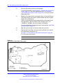
The following figure illustrates some of the preceding terms.
Figure 14
Example showing deployment terms
Nortel Communication Server 1000
SIP DECT Fundamentals
NN43120-123 02.02 30 March 2010
Copyright © 2008-2010 Nortel Networks. All Rights Reserved.
44 Site planning and hardware deployment
Deploying on a single floor
Use the information in this section when you are installing SIP DECT on a
single floor.
Identify critical points when installing on a single floor.
Procedure 3
Identifying critical points on the floor
Step
Action
1
Mark critical points.
A critical point is a place that can be difficult for the radio signal
to reach, such as a corner of a room, lifts, and stairwells. Initial
critical points are shown in Figure 15 "Example of initial critical
points" (page 44) as: P1, P2, P3, P5, P6 and P7.
--End--
Figure 15
Example of initial critical points
A specific RSSI value on the handset defines the cell boundary range.
Links can be made outside the cell boundary but the audio quality of the
link is poor. The link drops if the handset and the basestation are too far
apart.
Nortel Communication Server 1000
SIP DECT Fundamentals
NN43120-123 02.02 30 March 2010
Copyright © 2008-2010 Nortel Networks. All Rights Reserved.
System deployment 45
As shown in Figure 16 "Cell boundary terminology" (page 45), the cell
boundary is the farthest point from the cell center where a clear radio
signal can be heard.
Determine the range from the cell center to the cell boundary, or the
distance to a potential cell center from a critical point, by using the cell
boundary value and the deployment tool.
ATTENTION
Close all doors, and hold the survey handset about 1.2 m above the ground.
Figure 16
Cell boundary terminology
Determine a cell boundary for the cell center by placing the deployment
tool at the cell center and using the deployment handset to establish the
cell boundary.
Mark the cell contour based on the most distant point.
Procedure 4
Demarcating the cell contour for the critical point farthest from the center of
the full coverage area
Step
Action
1
Set up the deployment tool basestation. Raise the deployment
tool basestation as high as possible, or until it is at the height
recommended for basestations.
Nortel Communication Server 1000
SIP DECT Fundamentals
NN43120-123 02.02 30 March 2010
Copyright © 2008-2010 Nortel Networks. All Rights Reserved.
46 Site planning and hardware deployment
2
Enter the site survey mode on the handset.
For more information, see Procedure 1 “Entering the site survey
mode” (page 41) if you use Deployment Kit 2, or Procedure
149 “Entering the monitor mode” (page 270) if you use an older
Deployment tool.
3
Measure the range into the coverage area in a few directions to
determine where a cell center can be located and still be within
range of the critical point.
Listen to the deployment tool handset while moving away from
the basestation. After the RSSI value changes from 7 to 6
(--80dBm to --85dBm), the cell boundary is detected.
For more information about deployment requirements, see“Radio
synchronization” (page 19).
4
Mark the cell boundary on the floor plan with a small x.
5
Repeat step 3 and step 4 until you have sufficient Xs to draw a
thin contour arc through the Xs.
In Figure 17 "Cell contour of the initial critical point" (page 46),
P1 is the initial critical point.
--End--
Figure 17
Cell contour of the initial critical point
Nortel Communication Server 1000
SIP DECT Fundamentals
NN43120-123 02.02 30 March 2010
Copyright © 2008-2010 Nortel Networks. All Rights Reserved.
System deployment 47
Procedure 5
Demarcating the cell contour of the closest adjacent critical point to the first
critical point.
Step
Action
1
Repeat the described steps in Procedure 4 “Demarcating the cell
contour for the critical point farthest from the center of the full
coverage area” (page 45) to mark the cell contour of the closest
adjacent critical point to the first critical point.
In Figure 18 "Cell contour of the closest adjacent critical point
to the initial critical point" (page 47), P2 is the closest adjacent
critical point to the first critical point.
--End--
Figure 18
Cell contour of the closest adjacent critical point to the initial critical point
Locate the cell center.
Nortel Communication Server 1000
SIP DECT Fundamentals
NN43120-123 02.02 30 March 2010
Copyright © 2008-2010 Nortel Networks. All Rights Reserved.
48 Site planning and hardware deployment
Procedure 6
Locating the cell center
Step
Action
1
Place the deployment tool at one critical point and then use the
deployment handset to obtain a change in audio quality. The
audio quality change determines the cell boundary contour.
2
Repeat step 1 at an adjacent critical point. The call center is
where the cell boundaries of both critical points meet. Mark the
cell center position on a floor plan.
3
Use the cell contours to locate a cell center.
Locate the cell center where the cell contours meet. Choose a
position on the floor plan that meets the following requirements:
•
•
•
is farthest from the critical points
•
is in the coverage area
provides good audio quality at the critical point,
complies with the requirements described in section
“Deployment requirements” (page 18)
Label the cell center on the floor plan with the following symbol.
xCn, where x = the floor and n = is the cell number in sequence
of the entire plan.
In Figure 19 "Example of a cell center" (page 49), IC1 is a cell
center.
--End--
Nortel Communication Server 1000
SIP DECT Fundamentals
NN43120-123 02.02 30 March 2010
Copyright © 2008-2010 Nortel Networks. All Rights Reserved.
System deployment 49
Figure 19
Example of a cell center
Mark the cell boundary.
Procedure 7
Demarcating a cell boundary
Step
Action
1
Set up the deployment tool basestation at the cell center.
2
Enter the site survey mode on the handset.
For more information, see Procedure 1 “Entering the site survey
mode” (page 41) if you use Deployment Kit 2, or Procedure
149 “Entering the monitor mode” (page 270) if you use an older
Deployment tool.
3
See the floor plan and check audio quality in user offices
within the cell. If a user office is in a zone where audio quality
deteriorates, relocate the cell center closer to the critical point or
the office.
4
Walk into all the areas (rooms) necessary to mark the complete
cell boundary. Radio signals travel further in uncluttered areas
than in cluttered areas. Record the cell boundary.
5
Find the cell boundary by measuring the range and marking it
on the floor plan with a small x. Repeat steps Step 3 and Step
Nortel Communication Server 1000
SIP DECT Fundamentals
NN43120-123 02.02 30 March 2010
Copyright © 2008-2010 Nortel Networks. All Rights Reserved.
50 Site planning and hardware deployment
4 until there you have sufficient Xs so you can draw a contour
arc around the cell center.
For an example of a cell boundary, see Figure 20 "Example of a
cell center boundary" (page 50).
--End--
Figure 20
Example of a cell center boundary
Mark and label the cell boundary.
Procedure 8
Marking and labeling the cell boundary on the floor plan
Step
Action
1
Mark each office within the cell that is isolated from the office
area.
2
Label subsequent critical points on the floor plan with the
following symbol.
3
Mark the cell contour on the floor plan by tracing a contour line
through the Xs with a marker.
Nortel Communication Server 1000
SIP DECT Fundamentals
NN43120-123 02.02 30 March 2010
Copyright © 2008-2010 Nortel Networks. All Rights Reserved.
System deployment 51
4
Trace the cell boundaries and cell centers with colored markers.
--End--
Identify new critical points.
Procedure 9
Identifying new critical points
Step
Action
1
Identify one new critical point slightly inside of where the cell
boundary meets the outside wall.
In Figure 21 "Example of new critical points (P8 and P9)" (page
52), this new critical point is P9.
2
Identify another new critical point which is adjacent to the first
new critical point.
Locate this critical point on the opposite side of the cell boundary
area.
In Figure 21 "Example of new critical points (P8 and P9)" (page
52), the cell boundary area is IC1 and the new critical point is
P8.
--End--
Nortel Communication Server 1000
SIP DECT Fundamentals
NN43120-123 02.02 30 March 2010
Copyright © 2008-2010 Nortel Networks. All Rights Reserved.
52 Site planning and hardware deployment
Figure 21
Example of new critical points (P8 and P9)
Mark and label new critical points.
Procedure 10
Marking and labeling new critical points
Step
Action
1
Mark and label these new critical points on the floor plan with the
following symbol.
For more information, see Procedure 8 “Marking and labeling the
cell boundary on the floor plan” (page 50).
--End--
Mark new cell contours and a new cell boundary.
Nortel Communication Server 1000
SIP DECT Fundamentals
NN43120-123 02.02 30 March 2010
Copyright © 2008-2010 Nortel Networks. All Rights Reserved.
System deployment 53
Procedure 11
Demarcating new cell contours, a new center and a new cell boundary
Step
Action
1
Using the critical points from Procedure 9 “Identifying new critical
points” (page 51), mark new cell contours, a new cell center and
a new cell boundary.
For more information, see Procedure 4 “Demarcating the cell
contour for the critical point farthest from the center of the full
coverage area” (page 45) to Procedure 7 “Demarcating a cell
boundary” (page 49).
Cell contour arcs must pass near the cell boundary of adjacent
cells. For an example, see Figure 22 "Example of deployment
for cell center 1C2" (page 53).
--End--
Figure 22
Example of deployment for cell center 1C2
Mark cell contours, centers, and boundaries at the far end of the intended
coverage area.
Nortel Communication Server 1000
SIP DECT Fundamentals
NN43120-123 02.02 30 March 2010
Copyright © 2008-2010 Nortel Networks. All Rights Reserved.
54 Site planning and hardware deployment
Procedure 12
Demarcating additional cell contours, centers and boundaries at the far end
of the building
Step
Action
1
Repeat the procedures Procedure 3 “Identifying critical points
on the floor” (page 44) toProcedure 10 “Marking and labeling
new critical points” (page 52) as necessary to mark new cell
boundaries at the other end of the building. In Figure 23
"Example of deployment for cells 1C3 and 1C4" (page 54), new
cells are formed around cell centers IC3 and IC4.
--End--
Figure 23
Example of deployment for cells 1C3 and 1C4
Identify new critical points.
Procedure 13
Identifying new critical points
Step
Action
1
Mark critical points adjacent to a critical point and on the
opposite side of the cell boundary area. (critical point = P11 in
Figure 24 "Identify new critical points (P11, P12, P13, P14, P15,
P16, P17)" (page 55), where cell boundary area = IC2),
Nortel Communication Server 1000
SIP DECT Fundamentals
NN43120-123 02.02 30 March 2010
Copyright © 2008-2010 Nortel Networks. All Rights Reserved.
System deployment 55
The critical points must be as follows.
2
Mark critical points inside of where the cell boundary meets the
outside wall (P12, P13, P14, and P15 in Figure 24 "Identify new
critical points (P11, P12, P13, P14, P15, P16, P17)" (page 55),
and
3
Mark critical points where cell boundaries meet (P16 and P17 in
Figure 24 "Identify new critical points (P11, P12, P13, P14, P15,
P16, P17)" (page 55).
--End--
Figure 24
Identify new critical points (P11, P12, P13, P14, P15, P16, P17)
Mark additional cell boundaries and define the extent of the coverage area.
Procedure 14
Demarcate additional cell boundaries to cover all areas of the building
Step
Action
1
Repeat the procedures Procedure 3 “Identifying critical points
on the floor” (page 44) to Procedure 10 “Marking and labeling
new critical points” (page 52) as necessary to mark new cell
boundaries at the middle of the building.
Nortel Communication Server 1000
SIP DECT Fundamentals
NN43120-123 02.02 30 March 2010
Copyright © 2008-2010 Nortel Networks. All Rights Reserved.
56 Site planning and hardware deployment
Critical points P11, P13 and P16 form the following:
•
contours in Figure 25 "Contours formed by critical points P11,
P13, and P16" (page 56)
•
the cell center 1C5 in Figure 26 "Cell center 1C5 formed by
critical points P11, P13, and P16" (page 57)
•
a new cell boundary in Figure 27 "Cell boundary 1C5 formed
by critical points P11, P13, and P16" (page 57)
Critical points P11, P12, and P17 form the following:
•
contours in Figure 28 "Example of critical point cell
boundaries" (page 58)
•
a new boundary based on cell center 1C6 in Figure 29
"Example of cell center boundary 1C6" (page 58)
Figure 25 "Contours formed by critical points P11, P13, and P16"
(page 56) shows a floor plan with complete radio coverage. Cell
boundary 1C7 completes the floor plan.
--End--
Figure 25
Contours formed by critical points P11, P13, and P16
Nortel Communication Server 1000
SIP DECT Fundamentals
NN43120-123 02.02 30 March 2010
Copyright © 2008-2010 Nortel Networks. All Rights Reserved.
System deployment 57
Figure 26
Cell center 1C5 formed by critical points P11, P13, and P16
Figure 27
Cell boundary 1C5 formed by critical points P11, P13, and P16
Nortel Communication Server 1000
SIP DECT Fundamentals
NN43120-123 02.02 30 March 2010
Copyright © 2008-2010 Nortel Networks. All Rights Reserved.
58 Site planning and hardware deployment
Figure 28
Example of critical point cell boundaries
Figure 29
Example of cell center boundary 1C6
Nortel Communication Server 1000
SIP DECT Fundamentals
NN43120-123 02.02 30 March 2010
Copyright © 2008-2010 Nortel Networks. All Rights Reserved.
System deployment 59
Deploying on multiple floors
Use the information in this section to deploy SIP DECT in the following
situations.
•
•
The coverage area is on more than one floor.
The floors are not adjacent.
Checking for through-the-floor coverage
The first step in covering a multi-floor building is to assess the availability
of through-the-floor coverage. In buildings mainly constructed of wood,
you can use through-the-floor coverage. However, due to the construction
of most modern buildings with raised floors, high metal content, and
reinforced concrete, through-the-floor coverage with DECT is limited.
Procedure 15
Checking for through-the-floor coverage
Step
Action
1
Place the deployment tool in a middle floor of the site.
2
Go to the floor above the deployment tool and enter the site
survey mode on the handset.
For more information, see Procedure 1 “Entering the site survey
mode” (page 41) if you use Deployment Kit 2, or Procedure
149 “Entering the monitor mode” (page 270) if you use an older
Deployment tool.
3
Measure the deployment contour as if the basestation was on
this floor, instead of the floor below.
If only a small area is covered (less than a 10 metre radius), no
through-the-floor coverage is available on the floor above an
installed basestation.
4
Go to the floor below the deployment tool and repeat the
preceding process.
If only a small area is covered (less than a 10 metre radius), no
through-the-floor coverage is available on the floor below an
installed basestation.
5
If there is no through-the-floor coverage or coverage is restricted
to a small area, deploy each floor using critical points, or if the
floors have similar floor plans, you can use the same deployment
plan on each floor.
--End--
Nortel Communication Server 1000
SIP DECT Fundamentals
NN43120-123 02.02 30 March 2010
Copyright © 2008-2010 Nortel Networks. All Rights Reserved.
60 Site planning and hardware deployment
Assess floor layout
The deployment procedure changes according to the similarities and
differences of the floors.
•
All floors have the same layout.
To begin a multi-floor deployment if all floors have the same layout,
deploy one floor and enter the data on the floor plan. Use the data
from the deployed floor for other identical floors.
For example, if the second floor of an office tower is laid out with
cubicle style offices with a perimeter of enclosed offices, and the third
floor is laid out in the same manner, both floors can have the same
installation profile for basestations.
•
All floors do not have the same layout.
If the floor plan varies from floor to floor, use the critical point method
to deploy each distinct floor. For more information, see “Prepare the
tool for deployment” (page 264).
Do not underestimate the importance of changes in floor layout. Simple
changes in a room from a meeting room to a storage room can have
significant impact on the coverage from a basestation.
Multi floor coverage situations
The following situations require multi-floor coverage.
•
•
•
“Atriums” (page 60)
“High rise buildings” (page 61)
“Unusual conditions” (page 61)
Atriums Cells in an atrium, as shown in Figure 30 "An atrium" (page
61), are usually larger than the cells of the remainder of the building. Use
the information in this section as a guide help you to plan an atrium. No
precise steps to follow when you deploy an atrium, but you must consider
several points. For more information, see “Unusual conditions” (page 61) .
Nortel Communication Server 1000
SIP DECT Fundamentals
NN43120-123 02.02 30 March 2010
Copyright © 2008-2010 Nortel Networks. All Rights Reserved.
System deployment 61
Figure 30
An atrium
Consider the following points to deploy in an atrium:
•
•
•
Plan atriums to the full height.
•
Do not place cell centers in an atrium if you intend for them to serve
adjacent areas.
•
•
To serve adjacent areas, place the cell centers into these areas.
•
If cell centers in adjacent dense areas serve one floor of an atrium,
verify the coverage of the cell on all of the floors that meet with the
atrium.
Plan an atrium as one full size room, not floor by floor.
Place cell centers within an atrium only if you intend for them to cover
the atrium.
Deploy the atrium first if the atrium is more than one-third the size of
the building, or more than one cell in size.
High rise buildings Deploy a high rise building as an unusual type of
multi-floor deployment.
Test through-the-floor coverage first. If there is no through-the-floor
coverage, deploy each floor. Repeat the deployment for all floors with the
same layout. In all other cases deploy floor by floor. You must deploy a
floor with many meeting rooms deploys differently from how you deploy
an area with cubicles.
Unusual conditions No precise steps exist to follow when you deploy in
unusual condition, but you must consider several points.
Nortel Communication Server 1000
SIP DECT Fundamentals
NN43120-123 02.02 30 March 2010
Copyright © 2008-2010 Nortel Networks. All Rights Reserved.
62 Site planning and hardware deployment
To plan an unusual condition, consider the following situations.
•
•
•
“Cell centers are too close” (page 62)
“Cell centers are too far apart” (page 62)
“Too many cell centers” (page 63)
Cell centers are too close If you deploy cell centers less than 10 metres
apart, the handsets can initiate unnecessary handover. Unnecessary
handover results in excessive internal messaging and degraded speech
quality.
Cell centers are too far apart If you deploy cell centers too far apart,
the edge of a cell does not overlap the coverage from another cell.
Cell centers must be within the edge of other cell centers to provide
satisfactory overlap.
Overlap can be difficult to achieve where coverage is received from the
floor above or the floor below. Internal structures can cause overlap
deficiencies.
Place cell centers within the cell boundary, as indicated by the deployment
tool.
The installation of basestations in places other than the location shown on
the plan can cause coverage problems; for example, if the basestation is
mounted on the opposite side of a wall from its planned location.
Consider the following for basestation locations.
•
•
•
•
•
•
Choose locations where you can easily mount basestations.
Install basestations as close as possible to planned locations.
Follow safety codes, and be aware aesthetics.
Allow sufficient access to install basestations.
Provide clear installation instructions.
Test the coverage during post-deployment checks.
Nortel Communication Server 1000
SIP DECT Fundamentals
NN43120-123 02.02 30 March 2010
Copyright © 2008-2010 Nortel Networks. All Rights Reserved.
System deployment 63
Too many cell centers The primary concern with deploying too many
cell centers is cost. To deploy the correct number of cell centers and
minimize cost, perform the following steps:
•
•
Verify the coverage and traffic volume before you add additional cells.
•
•
Verify the coverage area of each cell.
Remove a cell served by other cells unless it is required for high
handset density.
Verify that at least one area that each cell serves is not served by
another cell.
In the example in Figure 31 "Locating redundant cells" (page 63), cell 1C3
is redundant unless required for high handset density.
Figure 31
Locating redundant cells
Reengineer cells for high traffic areas
To accommodate the demand in high traffic areas, follow “The cell
reengineering process” (page 64).
Traffic volume
The deployment process ensures coverage throughout the service area.
It does not, however, take into account the effect of traffic. To support the
volume of telephone calls in cells that carry high traffic, you must increase
the number of cells deployed.
The calculation of expected telephone traffic includes an allowance for the
user population in a cell and for the roaming user.
Nortel Communication Server 1000
SIP DECT Fundamentals
NN43120-123 02.02 30 March 2010
Copyright © 2008-2010 Nortel Networks. All Rights Reserved.
64 Site planning and hardware deployment
The cell reengineering process
The following sections describe the reengineering process.
•
•
•
•
“Estimating traffic within a cell” (page 64)
“Separating the coverage area and recording the number of offices”
(page 65)
“Creating an estimate table” (page 65)
“Calculating the number of users inside the cell with an office” (page
66)
•
“Calculating the number of users with an office outside the cell who
walk into the cell” (page 67)
•
•
•
•
•
“Calculating the number of users without an office” (page 68)
“Totalling the estimate for users in a cell” (page 69)
“Calculating the data for all remaining cells” (page 70)
“Creating a table to document telephone types in a cell” (page 71)
“Determining cell reengineering” (page 71)
Estimating traffic within a cell To adjust the number of users supported
by the system, you can modify the deployment procedures you followed in
“Deploying on a single floor” (page 44) or “Deploying on multiple floors”
(page 59). Perform the following three steps to estimate traffic within a cell:
•
•
•
Determine the number of handset users with an office within each cell.
Determine how many users have wired phones.
Determine how many users without an office are normally in each cell.
Some users have both wired and handset phones; other users rely on
handsets only.
Re-engineered cells for high traffic areas are represented by an adjusted
estimate for the two groups: handset and wireless, and handset only. Use
the adjusted estimate to determine whether the cell sizes can handle the
telephone traffic.
If the traffic-handling capacity of the cells is not adequate, use 12-channel
basestations and subdivide them into smaller cells to ensure the traffic is
handled properly according to the instructions.
Nortel Communication Server 1000
SIP DECT Fundamentals
NN43120-123 02.02 30 March 2010
Copyright © 2008-2010 Nortel Networks. All Rights Reserved.
System deployment 65
Figure 32
Example of dividing the coverage area and recording offices
Procedure 16
Separating the coverage area and record the number of offices
Step
Action
1
Divide the floor plan into cell areas.
Mark the cell areas on the floor plan, one area for each cell, and
split cell overlap areas in half, as shown in Figure 32 "Example
of dividing the coverage area and recording offices" (page 65) as
heavy dotted lines.
2
Count the number of user offices in each cell area.
3
Record the number of user offices on the floor plan in each cell
area.
--End--
Creating an estimate table Use the following table to estimate the
number of handset users for each cell.
Nortel Communication Server 1000
SIP DECT Fundamentals
NN43120-123 02.02 30 March 2010
Copyright © 2008-2010 Nortel Networks. All Rights Reserved.
66 Site planning and hardware deployment
Table 5
Estimate users in a cell
Estimate for:
1C1
1C2
1C3
1Cn
Users inside the
cell with an office
Users with an
office outside of a
cell who walk into
the cell
Users without an
office
Users in a cell
Procedure 17
Creating an estimate table
Step
Action
1
Make an estimate table.
Include a column for each cell center.
2
Label the rows as shown in Table 5 "Estimate users in a cell"
(page 66).
3
Label each column heading with the cell center indicator.
Use this table to determine how many times to subdivide each
cell to carry the handset telephone traffic.
--End--
Table 6
Example of the table first row calculation
Estimate
for:
Users
inside the
cell with
an office
1C1
1C2
1C3
1C4
1C5
8.4
Users
with an
office
outside of
a cell who
walk into
the cell
Nortel Communication Server 1000
SIP DECT Fundamentals
NN43120-123 02.02 30 March 2010
Copyright © 2008-2010 Nortel Networks. All Rights Reserved.
1C6
1C7
System deployment 67
Table 6
Example of the table first row calculation (cont’d.)
Estimate
for:
1C1
1C2
1C3
1C4
1C5
1C6
1C7
Users
without an
office
Users in a
cell
Procedure 18
Calculating the number of users inside the cell with an office
Step
Action
1
Estimate the number of users in the first cell with an office.
Use the formula: (users with an office in the cell × 0.7)
2
Enter the result in the row Users inside the cell with an office.
In the example in Figure 32 "Example of dividing the coverage
area and recording offices" (page 65), 12 users in cell 1C1 spend
70 percent of their time in their offices (12 × 0.7 = 8.4) .
--End--
Calculating the number of users inside the cell with an office Traffic
engineering demonstrates that handset users with an office spend 70
percent of their time within their home cell.
Table 7
Example of the table second row calculation
Estimate
for:
1C1
Users
inside the
cell with
an office
8.4
Users
with an
office
outside of
a cell who
walk into
the cell
3.2
1C2
1C3
1C4
1C5
Nortel Communication Server 1000
SIP DECT Fundamentals
NN43120-123 02.02 30 March 2010
Copyright © 2008-2010 Nortel Networks. All Rights Reserved.
1C6
1C7
68 Site planning and hardware deployment
Estimate
for:
1C1
1C2
1C3
1C4
1C5
1C6
1C7
Users
without an
office
Users in a
cell
Procedure 19
Calculating the number of users with an office outside the cell who walk into
the cell
Step
Action
1
Estimate the number of users in the first cell with an office
outside of the cell who walk into the cell.
2
Use the following formula:
3
Enter the result in the row Users with an office outside the cell
who walk into the cell.
The example in Figure 32 "Example of dividing the coverage
area and recording offices" (page 65), shows 75 telephone
users, minus the 12 users already in cell 1C1. Therefore, 63
users can walk into cell 1C1. However, the 63 walk-in users
spend only 30 percent of their time outside their offices. Seven
cells exist on the floor plan minus cell 1C1. Accordingly, an
estimate of 3.2 walk-in users can be in cell 1C1.
--End--
Table 8
Example of the table third row calculation
Estimate
for:
1C1
Users
inside the
cell with
an office
8.4
1C2
1C3
1C4
1C5
Nortel Communication Server 1000
SIP DECT Fundamentals
NN43120-123 02.02 30 March 2010
Copyright © 2008-2010 Nortel Networks. All Rights Reserved.
1C6
1C7
System deployment 69
Table 8
Example of the table third row calculation (cont’d.)
Estimate
for:
1C1
Users
with an
office
outside of
a cell who
walk into
the cell
3.2
Users
without an
office
0
1C2
1C3
1C4
1C5
1C6
1C7
Users in a
cell
Procedure 20
Calculating the number of users without an office
Step
Action
1
Calculate the estimate for users in the first cell without an office.
Use the following formula:
2
Enter the result in the row Users without an office.
In the example shown in Figure 32 "Example of dividing the
coverage area and recording offices" (page 65), no users are
without an office.
--End--
Table 9
Example of the table first column total
Estimate for:
1C1
Users inside the cell with an
office
8.4
Users with an office outside
of a cell who walk into the
cell
3.2
1C2
1C3
1C4
1C5
Nortel Communication Server 1000
SIP DECT Fundamentals
NN43120-123 02.02 30 March 2010
Copyright © 2008-2010 Nortel Networks. All Rights Reserved.
1C6
1C7
70 Site planning and hardware deployment
Estimate for:
1C1
1C2
1C3
1C4
1C5
1C6
1C7
0
Users without an office
11.6
Users in a cell
Procedure 21
Totalling the estimate for users in a cell
Step
Action
1
Total the number of users in the first cell by adding the three
rows in the first column.
2
Enter the result in the bottom row users in a cell.
For the example in Figure 32 "Example of dividing the coverage
area and recording offices" (page 65), the 1C1 handset estimate
equals 11.6.
8.4 + 3.2 + 0 = 11.6.
--End--
Table 10
Example of a completed estimate table
Estimate for:
1C1
1C2
1C3
1C4
1C5
1C6
1C7
Users inside the cell with an
office
8.4
0.7
21.0
14.7
0.7
4.9
2.1
Users with an office outside
of a cell who walk into the
cell
3.2
3.7
2.3
2.7
3.7
3.4
3.6
0
0
0
0
0
0
0
11.6
4.4
23.3
17.7
4.4
8.3
5.7
Users without an office
Users in a cell
Procedure 22
Calculating the data for all remaining cells
Step
Action
1
Repeat the previous four procedures to calculate the remaining
user cell estimates.
2
Enter the result in the estimate table.
The information in Figure 32 "Example of dividing the coverage
area and recording offices" (page 65), is entered into Table
10 "Example of a completed estimate table" (page 70). This
Nortel Communication Server 1000
SIP DECT Fundamentals
NN43120-123 02.02 30 March 2010
Copyright © 2008-2010 Nortel Networks. All Rights Reserved.
System deployment 71
table shows the results of the calculations for cells that require
reengineering.
--End--
Creating a table to document telephone types in a cell Use a table
like Table 11 "Telephone types in a cell" (page 71) to record the various
telephone types in each cell.
Table 11
Telephone types in a cell
Telephone type
1C1
1C2
1C3
1Cn
User telephone types
Use the following symbols in each cell to denote the type of telephones
in use in the cell.
•
H&W for a cell in which all the users have both wired and handsets
(wireless phones).
•
•
H for a cell in which users have only handsets (wireless phones).
M for a mix of H and H&W users
Procedure 23
Creating a table to document telephone types in a cell
Step
Action
1
Make a Telephone types table.
2
Label the row User telephone types and include a column for
each cell center.
3
Label each column heading with the cell center indicator.
Use the information in this table to determine the number of cells
that require reengineering.
--End--
Table 12
Example of a completed estimate table
Estimate for:
1C1
1C2
1C3
1C4
1C5
1C6
1C7
Users inside the cell with an
office
8.4
0.7
21.0
14.7
0.7
4.9
2.1
Nortel Communication Server 1000
SIP DECT Fundamentals
NN43120-123 02.02 30 March 2010
Copyright © 2008-2010 Nortel Networks. All Rights Reserved.
72 Site planning and hardware deployment
Estimate for:
1C1
1C2
1C3
1C4
1C5
1C6
1C7
Users with an office outside
of a cell who walk into the
cell
3.2
3.7
2.3
2.7
3.7
3.4
3.6
0
0
0
0
0
0
0
11.6
4.4
23.3
17.7
4.4
8.3
5.7
Users without an office
Users in a cell
Table 13
Example of a completed telephone types table
Telephone type
1C1
1C2
1C3
1C4
1C5
1C6
1C7
User telephone types
H&W
H&W
M
M
H&W
H&W
H&W
Table 14
Cell reengineering
Estimate for:
Users with both a
handset and a wired
telephone
Users with only a handset
Action
From 0 up to 20
From 0 up to 12
Keep cell size as deployed.
Greater than 20
Greater than 12
Subdivide the cella to meet the
preceding conditions.
a. For information about how to subdivide cells, see “High handset density deployment” (page 75).
Determining cell reengineering Use Table 14 "Cell reengineering"
(page 72) only for user types H&W and H. For user type M see “A mix of
users with and without wired telephones in a cell” (page 73) .
Note:
Procedure 24
Determining cell reengineering
Step
Action
1
Find the number of users for users in the first cell.
In the example shown in Table 12 "Example of a completed
estimate table" (page 71), the handset estimate is 11.6.
2
Determine the telephone types in the first cell.
In the example shown in Table 12 "Example of a completed
estimate table" (page 71), the telephone type is H&W.
3
Locate the telephone type column in Table 12 "Example of a
completed estimate table" (page 71).
In the example H&W is the users with both a handset and a
wired telephone.
Nortel Communication Server 1000
SIP DECT Fundamentals
NN43120-123 02.02 30 March 2010
Copyright © 2008-2010 Nortel Networks. All Rights Reserved.
System deployment 73
4
Find the handset estimate range in Table 14 "Cell reengineering"
(page 72).
In the example, 11.6 falls within the From 0 up to 20 category.
5
Determine if a cell requires division or uses a 12-channel
basestation.
In the example From 0 up to 20, division is not required.
6
Repeat the preceding steps to determine the required number of
cells that need subdivision, except for telephone types M. For M
see “A mix of users with and without wired telephones in a cell”
(page 73) .
7
Transfer the results into the provisioning records.
--End--
Cell division requirements in special cases
This section describes how to determine cell division in the following
special cases.
•
•
where no office information is available.
where a mix of handset users exist with and without wired telephones
No office information If the location of the offices of users is not
known, calculate the estimated number of handsets for each cell using
this formula.
The formula is based on the assumption that users are located evenly
throughout the cells. However, most users offices are clustered in specific
areas of a building.
The formula has limitations as cells can vary in size. The method
described starting on “The cell reengineering process” (page 64) provides
accurate cell division results.
A mix of users with and without wired telephones in a cell Use
this procedure for mixed handset users. Telephone traffic generated by
handset users equates to that of handset and wired users. Combine the
two groups for cell size recalculation.
Nortel Communication Server 1000
SIP DECT Fundamentals
NN43120-123 02.02 30 March 2010
Copyright © 2008-2010 Nortel Networks. All Rights Reserved.
74 Site planning and hardware deployment
Table 15
Adjustment for users without wired telephones
Estimated number of handsets for users
without wired telephones
Adjusted estimated number of handsets for
each cell
0
0
1
2
2
3
3
5
4
7
5
9
6
11
7
12
8
14
9
16
10
18
11
20
12
22
13
24
14
25
15
27
16
29
17
31
18
34
19
36
20
38
21
40
22
42
23
44
24
46
25
48
26
49
27
50
28
53
29
55
30
57
31
60
Nortel Communication Server 1000
SIP DECT Fundamentals
NN43120-123 02.02 30 March 2010
Copyright © 2008-2010 Nortel Networks. All Rights Reserved.
System deployment 75
Estimated number of handsets for users
without wired telephones
Adjusted estimated number of handsets for
each cell
32
62
33
64
34
66
35
69
36
71
37
73
38
76
39
78
40
80
Procedure 25
Adjusting for users without wired telephones
Step
Action
1
Count the number of user offices with handsets and wired
telephones (H&W), and record the number.
2
Count the number of user offices that have only wireless
handsets, (H).
3
Use Table 15 "Adjustment for users without wired telephones"
(page 74) to determine the equivalent number of H&W users and
record this number.
4
Add the numbers received from steps 1 and 3 to determine and
adjust the value for the number of users with wired telephones.
5
Use the first column of Table 15 "Adjustment for users without
wired telephones" (page 74) to determine if you must resize if the
cell as described in “Determining cell reengineering” (page 71) .
--End--
High handset density deployment
The high handset density deployment includes limiting the expected
number of handsets for each cell center.
Use the high handset density procedure if instructed to inTable 14 "Cell
reengineering" (page 72). Do not use more than one basestation for each
cell center.
Limit the anticipated number of handsets Limit the number of
handsets you anticipate for each cell center to the limits shown in Table 14
Nortel Communication Server 1000
SIP DECT Fundamentals
NN43120-123 02.02 30 March 2010
Copyright © 2008-2010 Nortel Networks. All Rights Reserved.
76 Site planning and hardware deployment
"Cell reengineering" (page 72). Subdivide high handset density areas only.
If a cell falls into the category of a high density area, use Procedure 26
“High handset density deployment” (page 76) to subdivide the cell.
Subdivide a cell To subdivide the area for smaller cells, divide the cell
into as many small cells as necessary to accommodate the number of
users in the area.
ATTENTION
If you install two DAPs close to each other for extra traffic density, ensure the
distance between the DAPs is always more than one meter and preferably more
than 5 meters.
Figure 33
Example of a subdivided cell
In Figure 33 "Example of a subdivided cell" (page 76), cell 1C1 has 140
handset users and cell 1C2 has 100 handset users. For example, Table
14 "Cell reengineering" (page 72) indicates the following:
•
If the handset users in cell 1C1 are all handset only users, one cell can
support 39 handset only users. Therefore, four cells are needed to
support 140 users (140÷39 = 3.5 cells).
•
If the handset users in cell 1C1 are handset and wired telephone
users, and one cell can support 83 users, two cells are needed to
support 140 handset and wired telephone users (140 ÷ 83 = 1.6 cells).
Procedure 26
High handset density deployment
Step
Action
1
Determine the number of handset users in the high-density
handset cell.
Count the number of users. Include users served by
through-the-floor coverage of this cell.
Nortel Communication Server 1000
SIP DECT Fundamentals
NN43120-123 02.02 30 March 2010
Copyright © 2008-2010 Nortel Networks. All Rights Reserved.
System deployment 77
2
Calculate the cell subdivisions as required.
Divide the number of users by the appropriate value (12 or 20)
shown in Table 14 "Cell reengineering" (page 72). Round up the
result to the next whole number. The result equals the number
of cells required after subdividing the cell.
3
Divide the cell.
Draw lines from the cell center to the critical points on the cell
boundary. InFigure 33 "Example of a subdivided cell" (page 76),
the cell 1C1 is divided into four sectors and cell 1C2 is divided
into three sectors.
4
Relocate new cell centers.
Mark new cell centers within the sectored areas.
5
Determine the number of handset users in the new cell areas.
6
Count the number of user offices within each smaller sector.
Ensure fewer user offices exist within the cell than the traffic
limit.
7
Take the deployment tool to the locations calculated on the floor
plan. Ensure that there is a location that meets the requirements
in “Deployment requirements” (page 18).
8
Ensure the new cells have complete coverage.
9
Use the deployment handset to check coverage.
10
Repeat the anticipated handsets for each cell calculation
to ensure that each smaller cell provides appropriate traffic
coverage to the users in the area.
--End--
Nortel Communication Server 1000
SIP DECT Fundamentals
NN43120-123 02.02 30 March 2010
Copyright © 2008-2010 Nortel Networks. All Rights Reserved.
78 Site planning and hardware deployment
Nortel Communication Server 1000
SIP DECT Fundamentals
NN43120-123 02.02 30 March 2010
Copyright © 2008-2010 Nortel Networks. All Rights Reserved.
79
.
Software requirements
Navigation
•
“Call server, signalling server, and SIP Line Gateway software” (page
79)
•
“DAP controller software” (page 79)
Call server, signalling server, and SIP Line Gateway software
For information about Call Server 1000E and Signaling Server installation,
see Communication Server 1000E Installation and Commissioning
(NN43041-310). For more information about SIP Line Gateway application
installation, see SIP Line Fundamentals (NN43001-508).
DAP controller software
This section contains the steps to configure the SIP DECT system. Before
you can use SIP DECT, you must install and configure the following
software on the DAP controller PC:
•
Microsoft Windows
You can install any of the following operating systems on the DAP
controller or manager PC.
— Windows 2000 Professional or Windows 2000 Server Service Pack
4 (SP4)
— Windows 2003 Server SP1 or SP2
— Windows 2003 Release 2
— Windows XP Professional SP2
This document does not provide the steps you must follow to install the
operating system. For information about installing Windows, see the
documentation that accompanied the Windows software.
Nortel Communication Server 1000
SIP DECT Fundamentals
NN43120-123 02.02 30 March 2010
Copyright © 2008-2010 Nortel Networks. All Rights Reserved.
80 Software requirements
If a firewall is installed on your DAP Controller PC, ensure the firewall
does not block the ports used for various services. For information,
see “Firewall protection” (page 80).
•
•
Internet Explorer 6.0 or later
Internet Information Services (IIS)
For information about installing IIS, see “Internet information services”
(page 80).
•
DHCP and TFTP servers
For information about installing DHCP and TFTP servers, see “DHCP
and TFTP servers” (page 87).
•
DAP Controller (IP DECT Configurator and DAP Manager)
For information about installing the DAP Controller, see “DAP
Controller” (page 102).
Firewall protection
Both Windows XP Professional and Windows 2003 Server have built-in
firewalls.
By default, the firewall under Windows XP Professional does not allow
incoming access. However, the IP DECT Configurator can automatically
change the firewall settings. Verify the firewall settings after installation.
If a third-party firewall program is installed on your DAP Controller PC,
ensure the firewall does not block the ports used for the SIP DECT
system. By default, some ports are defined in IP DECT Configurator.
The ports defined by default:
•
•
•
From 3000 to 22229--multicast
From 28000 to 28017--DAP Controller services
30160--CDA services
If you change default ports in the IP DECT Configurator, ensure that the
firewall settings are updated correctly.
Internet information services
The DAP controller or manager runs as a service under Windows.
Because the management interface is available through a Web interface,
you must install the Web Server IIS.
Nortel Communication Server 1000
SIP DECT Fundamentals
NN43120-123 02.02 30 March 2010
Copyright © 2008-2010 Nortel Networks. All Rights Reserved.
DAP controller software
81
In Windows 2000 Professional, Windows XP Professional and Windows
2003 Server, IIS is not automatically installed. The next sections describe
how to install IIS for Windows XP Professional, Windows 2000 and
Windows 2003.
Install and maintain IIS on Microsoft Windows 2000
Use the information in this section to install IIS on Windows 2000, and to
ensure that IIS starts.
Install IIS on a PC with Windows 2000
Install IIS.
Prerequisites
•
You must have the appropriate Windows installation CD-ROM
available to complete this procedure.
Procedure 27
Installing IIS for Windows 2000 Professional
Step
Action
1
Click Start > Settings > Control Panel.
The Control Panel appears.
2
Double-click Add/Remove Programs.
The Add/Remove Programs window appears.
3
Click Add/Remove Windows Components.
The Windows Components window appears.
4
In the Windows Components window, select the IIS check box.
5
Click Next.
6
Insert the Windows CD-ROM and follow the installation wizard
instructions.
--End--
Check IIS on PC with Windows 2000
Determine whether IIS is started, and start it if necessary.
Procedure 28
Checking IIS on PC with Windows 2000
Step
Action
1
Open Internet Explorer on the PC where IIS is installed.
Nortel Communication Server 1000
SIP DECT Fundamentals
NN43120-123 02.02 30 March 2010
Copyright © 2008-2010 Nortel Networks. All Rights Reserved.
82 Software requirements
2
In the address bar in Explorer, enter localhost/iisHelp/ and then
press enter.
3
If Help Information appears, IIS is running. You are finished
with this procedure.
4
If Help Information does not appear, check Windows Help and
search for IIS. Follow the instructions on Windows Help to check
whether or not IIS is started. If IIS is started, you are finished
with this procedure.
If IIS is not started, go to step 5.
5
If IIS is not started after you perform the instructions in steps 1 to
4 of this procedure, click Start, go to Settings, and click Control
Panel to manually start IIS. Double-click Administrative Tools,
and then double-click Computer Management.
6
Expand the Services and Applications node in the console tree
of the MMC and select Internet Information Services.
7
Click the right mouse button on Internet Information Services
to restart the services. Click the right mouse button on the lower
levels of Internet Information Services to stop or start the
individual services.
--End--
Install and maintain IIS on Microsoft Windows 2003
Perform the procedures in this section to install IIS on Windows 2003,
restart IIS, or verify that IIS is operating.
Installing IIS on a PC with Windows 2003
Install the IIS function on a PC with Windows 2003.
•
You must have the appropriate Windows installation CD-ROM
available to complete this procedure.
Procedure 29
Installing IIS on a PC with Windows 2003
Step
Action
1
Click Start > Control Panel.
2
Select Add/Remove Programs
The Add/Remove Programs window appears.
3
Click Add/Remove Windows Components.
4
In the Components window, double-click Application Server.
5
In the Components window, check ASP.NET.
Nortel Communication Server 1000
SIP DECT Fundamentals
NN43120-123 02.02 30 March 2010
Copyright © 2008-2010 Nortel Networks. All Rights Reserved.
DAP controller software
6
Select Internet Information Services and click Details.
The Internet Information Services (IIS) window appears.
7
Select the check boxes for Internet Information Services
Manager and Common Files. Do not change the remaining
check boxes.
Nortel Communication Server 1000
SIP DECT Fundamentals
NN43120-123 02.02 30 March 2010
Copyright © 2008-2010 Nortel Networks. All Rights Reserved.
83
84 Software requirements
8
Click OK.
9
Click OK again.
10
Follow the instructions provided by the installation Wizard, and
insert the Windows CD-ROM as prompted.
11
Close the Add/Remove Programs window, and close the Control
panel window.
--End--
Restart IIS on a PC with Windows 2003
Restart IIS.
Procedure 30
Restarting IIS
Step
Action
1
Click Start, and open the Control Panel.
2
Click Administrative Tools.
3
Click Computer Management.
4
Expand the Services and Applications node in the MMC and
select Internet Information Services.
5
Right-click the Internet Information Services and select All
Tasks.
The All Tasks menu appears.
6
Select Restart.
IIS restarts.
--End--
Check IIS on a PC with Windows 2003
Determine whether IIS started.
Procedure 31
Checking IIS on a PC with Windows 2003
Step
Action
1
Open Internet Explorer on the PC where IIS is installed.
2
In the address bar in Internet Explorer, enter localhost/iisstart
.htm.
Nortel Communication Server 1000
SIP DECT Fundamentals
NN43120-123 02.02 30 March 2010
Copyright © 2008-2010 Nortel Networks. All Rights Reserved.
DAP controller software
If IIS is not running properly you can restart IIS. For more
information, see Procedure 30 “Restarting IIS” (page 84).
--End--
Install and maintain IIS on Microsoft Windows XP
Use the information in this section to install IIS on Windows XP or verify
that IIS is operating.
Installing IIS on PC with Windows XP
Install the IIS function on a PC with Windows XP.
•
You must have the appropriate Windows installation CD-ROM
available to perform this procedure.
Procedure 32
Installing Web Server IIS with Windows XP
Step
Action
1
Click Start > Settings > Control Panel .
2
Double-click Add/Remove Programs.
The Add/Remove Programs window appears.
3
Click Add/Remove Windows Components.
4
Select Internet Information Services.
Nortel Communication Server 1000
SIP DECT Fundamentals
NN43120-123 02.02 30 March 2010
Copyright © 2008-2010 Nortel Networks. All Rights Reserved.
85
86 Software requirements
ATTENTION
Do not select the check box beside Internet Information Services.
5
Click Details.
6
In the details window, select the check box World Wide Web
Service.
7
Click OK.
8
Click Next.
9
Insert the Windows XP Professional CD. After the system
prompts to you insert the CD, click OK.
10
If the Welcome to Microsoft Windows XP window appears, click
Exit in the bottom left corner of the window. The appearance of
the window is result of the auto run on the CD.
11
In the Windows Components wizard, click Finish.
12
Close the Add/Remove Programs window, and close the
Control panel window.
13
If applicable, remove the CD, DVD, and floppy from your system.
Close all windows and restart your computer.
14
After the computer restarts, check that IIS is running. If not,
consult the Microsoft Web site. To check if IIS is running, see
“Check IIS on PC with Windows XP” (page 86).
--End--
Check IIS on PC with Windows XP
Determine whether IIS is started.
Procedure 33
Checking IIS on a PC with Windows XP
Step
Action
1
Open Internet Explorer on the computer where you want to
install the DAP manager.
2
Enter the URL localhost/localstart.asp.
3
Ensure that the Internet Information Services (IIS) page
appears.
Nortel Communication Server 1000
SIP DECT Fundamentals
NN43120-123 02.02 30 March 2010
Copyright © 2008-2010 Nortel Networks. All Rights Reserved.
DAP controller software
87
If the IIS start page does not appear, continue to “Installing
IIS on PC with Windows XP” (page 85) and install IIS on your
computer.
If the IIS start page appears, IIS is installed and running. Close
the window and proceed to “DHCP and TFTP servers” (page
87).
--End--
DHCP and TFTP servers
Each DAP receives an IP addresses, configuration file and firmware from
the IP network using a DHCP server and a TFTP server. Choose whether
to use the Microsoft Windows DHCP server or the TFTP server or both, or
the built-in DAP controller DHCP and TFTP servers.
DHCP servers and TFTP servers are the network components of the
Microsoft Windows 2003 Server and the Microsoft Windows 2000 Server.
Install these servers as services for the SIP DECT system functions. For
more information about Microsoft Windows 2000, 2003 DHCP and TFTP
server installation and configuration, see “DHCP and TFTP servers” (page
87).
The DAP controller software Release 4 includes DHCP and TFTP
servers that you can configure from the IP DECT Configurator. For more
information about built-in DHCP and TFTP servers, see “Built-in DHCP
and TFTP servers” (page 97).
Nortel Communication Server 1000
SIP DECT Fundamentals
NN43120-123 02.02 30 March 2010
Copyright © 2008-2010 Nortel Networks. All Rights Reserved.
88 Software requirements
You can create a DAP configuration without DHCP or TFTP; however
DHCP and TFTP must be available to program or reprogram DAPs. For
more information about DAP configuration without DHCP or TFTP, see
“DAP configuration without DHCP or TFTP servers” (page 102) .
If you prefer to use Microsoft Windows DHCP and TFTP servers, perform
the steps in Procedure 34 “Installing and configuring Microsoft Windows
DHCP server” (page 88) to install and configure DHCP servers. Perform
the steps in Procedure 37 “Installing the TFTP server” (page 95) to install
and configure TFTP servers.
If your DHCP server supports Vendor Class Identification option 60, use a
specific IP address range for the DAPs. The Vendor Class Identification of
the DAPs is D(ECT)AP 49.
Procedure 34
Installing and configuring Microsoft Windows DHCP server
Step
Action
1
Ensure that your DHCP server provides the following data to the
DAP.
•
•
•
•
IP Address
•
Configuration file name (dapcfg.txt) available through the
TFTP server (DHCP option 067)
Subnet Mask
Default Gateway IP address
Next Boot Server IP address that is the IP address of the
TFTP server (DHCP option 066)
You can install the DHCP server on the same server or on
another PC that runs the TFTP server.
The Microsoft DHCP server installation files are located on
the Microsoft Windows 2000/2003 Server CD-ROM package.
Licensing or registration charges or both may apply.
--End--
You can install the DHCP server on the same server on the same server
or on another PC that runs the TFTP server. The Microsoft DHCP server
(Windows 2000 / 2003) is in the Microsoft Windows 2000 / 2003 Server
CD-ROM package.
Nortel Communication Server 1000
SIP DECT Fundamentals
NN43120-123 02.02 30 March 2010
Copyright © 2008-2010 Nortel Networks. All Rights Reserved.
DAP controller software
The following procedures give examples of setting up the DHCP server
under Windows 2003 Server. This procedure also applies for Windows
2000 DHCP server, but with minor differences.
Procedure 35
Configuring DHCP server under Windows 2000 / 2003 server
Step
Action
1
From the Start menu, through the settings in Windows 2000,
open the Control Panel in Windows.
2
Open Add/Remove Programs.
3
Click Add/Remove Windows Components.
4
Select Networking Services and click Details.
The Components window appears.
5
Select the Dynamic Host Configuration Protocol (DHCP)
check box.
6
Click OK.
7
Click Next.
8
Insert the Windows 2003 CD-ROM as prompted.
9
Finish the procedure using the instructions in the dialog box.
Nortel Communication Server 1000
SIP DECT Fundamentals
NN43120-123 02.02 30 March 2010
Copyright © 2008-2010 Nortel Networks. All Rights Reserved.
89
90 Software requirements
10
Close the Add/Remove Programs window and close the
Control panel window.
--End--
Procedure 36
Configuring the Settings for SIP DECT
Step
Action
1
Start the DHCP manager: Start > Programs > Administrative
Tools > DHCP.
The DHCP Administration Tools window appears.
2
Select the active DHCP server and create a new scope: Action
> New Scope.
The New Scope Wizard starts.
3
Click Next in the wizard dialog box.
4
Enter a name and description for the new scope, for example,
SIP DECT.
5
Click Next in the naming dialog box see the IP address range.
The window New Scope Wizard—IP address range appears.
Nortel Communication Server 1000
SIP DECT Fundamentals
NN43120-123 02.02 30 March 2010
Copyright © 2008-2010 Nortel Networks. All Rights Reserved.
DAP controller software
91
6
Define a range of IP addresses for the DAPs used, for example,
192.168.100.200 to 210.
7
Define the associated subnet mask, for example, 255.255.255.0.
8
Click Next.
The window New Scope Wizard—Exclusion of an IP address
range appears.
9
Enter the Start IP address and End IP address values to
exclude, for example, the IP addresses of DHCP server and the
TFTP server.
This is necessary only if the IP address or addresses of
equipment with a fixed IP address is within the DHCP address
range. If it is not within the DHCP address range, leave this field
blank.
10
If you entered IP address ranges in step 6, click Add to save the
exclusion list.
11
Click Next.
The Lease Duration window appears.
12
Set the desired lease duration of the granted IP addresses to the
desired value.
Nortel Communication Server 1000
SIP DECT Fundamentals
NN43120-123 02.02 30 March 2010
Copyright © 2008-2010 Nortel Networks. All Rights Reserved.
92 Software requirements
13
Click Next.
The New Scope Wizard—Configure DHCP options appears.
14
Select No, and click Finish.
The newly created scope appears with a new line called Scope
Options.
15
Right-click Scope Options, and select Configure Options.
The Scope Options page appears.
Nortel Communication Server 1000
SIP DECT Fundamentals
NN43120-123 02.02 30 March 2010
Copyright © 2008-2010 Nortel Networks. All Rights Reserved.
DAP controller software
16
93
Select the Option 066 check box, and enter the IP address of the
TFTP server, for example, 192.168.100.10.
This can be the IP address of your DAP controller or manager, if
the TFTP server is running there.
17
Check Option 067 for the boot file name. Enter dapcfg.txt.
18
Select the Option 3 check box, and enter the Router or Default
Gateway IP address, for example, 192.168.100.1, and click Add.
Nortel Communication Server 1000
SIP DECT Fundamentals
NN43120-123 02.02 30 March 2010
Copyright © 2008-2010 Nortel Networks. All Rights Reserved.
94 Software requirements
19
Click Apply to save the changes and OK to close the dialog box.
20
Right-click Scope , and select Activate.
Now your DHCP server is configured correctly.
21
Close the DHCP window.
--End--
TFTP server
Many types of TFTP servers are available, including shareware and
freeware. A TFTP server must handle several accesses at the same time,
because several accesses occur at the same time, when the DAPs start
Nortel Communication Server 1000
SIP DECT Fundamentals
NN43120-123 02.02 30 March 2010
Copyright © 2008-2010 Nortel Networks. All Rights Reserved.
DAP controller software
95
simultaneously. Only a few TFTP servers can handle more than one
access at the same time. Some of these crash if the number of accesses
is too high.
Install a TFTP server on the Windows 2000 Server and the Windows 2003.
Procedure 37
Installing the TFTP server
Step
Action
1
If you have Windows 2003, go to Start > Control Panel in
Windows. If you have Windows 2000, go to Control Panel
through Settings.
2
Open Add/Remove Programs.
3
Click on the Add/Remove Windows Components.
The Windows Components Wizard window appears.
4
In the Components window, select the Remote Installation
Services check box.
5
Click Next.
6
Insert the Windows 2000 or Windows 2003 CD-ROM as
prompted.
7
Follow the instructions in the dialog box to complete the
procedure.
Nortel Communication Server 1000
SIP DECT Fundamentals
NN43120-123 02.02 30 March 2010
Copyright © 2008-2010 Nortel Networks. All Rights Reserved.
96 Software requirements
8
Close the Add/Remove Programs window and close the
Control panel window.
9
Click yes after you are prompted to restart the computer.
--End--
Procedure 38
Starting the TFTP server
Step
Action
1
If you have Windows 2003, go to Start > Control Panel. If you
have Windows 2000, go to Settings > Control Panel.
2
Open Administrative Tools.
3
Open Services.
The Services window appears.
4
Select Trivial FTP Deamon.
5
Right-click the Trivial FTP Deamon , and then select Start.
6
Right-click the Trivial FTP Deamon, and then select Properties.
7
Change the Startup Type setting to Automatic.
8
After you install TFTP on your PC with Windows 2000, a folder
named tftpdroot is created.
ATTENTION
If you run Windows 2003, you must create the TFTP folder on drive
C:, as shown in the following figure.
Nortel Communication Server 1000
SIP DECT Fundamentals
NN43120-123 02.02 30 March 2010
Copyright © 2008-2010 Nortel Networks. All Rights Reserved.
DAP controller software
97
--End--
Built-in DHCP and TFTP servers
The DAP controller software Release 4 has a built-in DHCP and
TFTP server. The built-in DHCP and TFTP servers do not require
manual configuration, because the IP DECT Configurator performs the
configuration.
ATTENTION
You can configure a Built-in DHCP and TFTP server only after you install the IP
DECT Configurator. For more information, see “DAP Controller” (page 102).
Built-in DHCP server
The DAP controller software Release 4 has a built-in DHCP server. This
server runs as an application that requires you to log on to Microsoft
Windows. You can use the IP DECT Configurator tool available under
DAP controller 4 to start or stop the DHCP server program.
This DHCP server responds to DHCP requests from DAPs because it
checks on Vendor Class Identification D(ECT) AP 49 from a DAP.
You can configure built-in DHCP server using the Network Settings
window of IP DECT Configurator.
Nortel Communication Server 1000
SIP DECT Fundamentals
NN43120-123 02.02 30 March 2010
Copyright © 2008-2010 Nortel Networks. All Rights Reserved.
98 Software requirements
Prerequisites If you are configuring a new system, perform the following
procedures before your configure the built-in DHCP server.
•
•
Procedure 43 “Starting the IP DECT Configurator” (page 109)
Procedure 44 “Adding a new system using the IP DECT Configurator”
(page 109)
Procedure 39
Configuring the built-in DHCP server using the IP DECT Configurator
Network Settings Window
Step
Action
1
Start the IP DECT Configurator, and select Modify the system.
2
Choose the system to modify.
3
Select the Run DHCP server on this PC check box.
4
Enter the DAP IP range, for example, 192.168.100.200-210.
5
Select the DAP IP Range exclusive for DAPs only.
6
Enter the Subnet Mask, for example, 255.255.255.0.
7
Enter the Default gateway, for example, 192.168.100.1.
8
Enter the TFTP IP address on the PC where the DAP controller
software is installed, for example, 192.168.100.10.
9
If you must assign manually IP addresses to the DAP, click
More.
10
Enter MAC address of the DAP and the IP address assigned
to the DAP.
You can add DAPs to the list, delete DAPs from the list, or edit
the addresses.
11
Click Apply to save the changes, or Close to exit.
Nortel Communication Server 1000
SIP DECT Fundamentals
NN43120-123 02.02 30 March 2010
Copyright © 2008-2010 Nortel Networks. All Rights Reserved.
DAP controller software
12
Click Apply.
13
Start the DHCP server with Start > All Programs > DAP
controller.
14
Restart the DAPs.
99
If you are configuring a new system, follow the steps in
Procedure 48 “Configuring SIP Settings” (page 113) instead of
restarting DAP.
--End--
Built-in TFTP server
The DAP controller 4 has a built-in TFTP server that runs as a service
under Microsoft Windows. You can use the IP DECT Configurator tool
available with the DAP controller 4 to start or stop the TFTP server
program. You can start or stop the service through the services window in
Microsoft Windows.
Configuration without DHCP or TFTP
ATTENTION
DAP configuration without DHCP or TFTP requires DHCP and TFTP to be
temporarily available to program or reprogram DAPs.
You can perform DAP configuration without DHCP or TFTP only after you install
the IP DECT Configurator. For more information, see “DAP Controller” (page
102).
Nortel Communication Server 1000
SIP DECT Fundamentals
NN43120-123 02.02 30 March 2010
Copyright © 2008-2010 Nortel Networks. All Rights Reserved.
100
Software requirements
You can install the DAPs in an IP environment without a DHCP server,
a TFTP server, or both. The IP environment can be a VLAN within the
company network where the IT manager does not allow a DHCP server.
This IP environment can also be a branch office where a few DAPs are
installed without a DHCP server.
If a DAP must operate without a DHCP server, a TFTP server, or both, the
DAP requires that the IP address and configuration data are stored in the
DAP on a semipermanent basis in FEPROM.
To store the IP address and configuration data on DAP, you must
temporarily connect a DHCP server and a TFTP server. The DHCP and
TFTP server can be on a stand alone PC with a network interface and a
DAP connected. The DHCP and TFTP server can also be on any other
computer in the network.
The DHCP server and TFTP server are required while you configure the
DAP, but are not required during normal operation.
ATTENTION
To store the data in the DAP, it is necessary that the DAP have a DHCP offer
with an Unlimited or Infinite lease. Ensure the DHCP server issues an Unlimited
or Infinite lease. The DHCP server with IP DECT Release 4 issues such a lease
by default.
If a Microsoft Windows DHCP server is configured, enable unlimited lease.
Procedure 40
Enabling unlimited lease
Step
Action
1
Start the DHCP manager: Start > Programs > Administrative
Tools > DHCP.
2
Right-click Scope , and select Properties.
The DHCP Administrative tools page appears.
3
Select Unlimited for Lease duration for DHCP clients.
Nortel Communication Server 1000
SIP DECT Fundamentals
NN43120-123 02.02 30 March 2010
Copyright © 2008-2010 Nortel Networks. All Rights Reserved.
DAP controller software
4
Click the Advanced Tab, and select Both for Assign IP
addresses dynamically to clients of and Unlimited for Lease
duration for OOTP clients.
Nortel Communication Server 1000
SIP DECT Fundamentals
NN43120-123 02.02 30 March 2010
Copyright © 2008-2010 Nortel Networks. All Rights Reserved.
101
102
Software requirements
5
Click OK to save changes.
--End--
DAP configuration without DHCP or TFTP servers You can perform
DAP configuration without DHCP or TFTP servers using the Network
Settings window of the IP DECT Configurator.
Configure a DAP to store IP address and configuration data.
Procedure 41
Storing IP address and configuration data on a DAP
Step
Action
1
Start the IP DECT Configurator and select Modify the system.
2
Select the system to modify.
3
Click More.
4
Select the DAP Boot Options check box.
5
Select Store IP configuration into flash memory.
6
Click Apply.
7
Click the Save system button in the left pane.
8
Ensure that the DHCP server is running and that the TFTP
server is running.
9
Restart the DAPs.
The IP data and configuration data is now stored into the DAPs
and the DAPs can function without the DHCP and TFTP servers.
--End--
DAP Controller
Perform the procedures in this section to install the DAP Controller from
the CD. You must execute this procedure only once, and thereafter use
the installation for any number of system configurations. You can change
settings later.
Nortel Communication Server 1000
SIP DECT Fundamentals
NN43120-123 02.02 30 March 2010
Copyright © 2008-2010 Nortel Networks. All Rights Reserved.
DAP controller software
103
Prerequisites
•
Install and configure IIS software.
For more information, see “Internet information services” (page 80).
•
Install and configure DHCP and TFTP servers if you use Microsoft
Windows DHCP and TFTP servers. For more information, see “DHCP
and TFTP servers” (page 87).
•
Ensure that you have DAP controller or manager software Release 4
or later.
•
•
Ensure that you have DAP firmware 4910b427.dwl or later.
Ensure that you have configured the IP addressing on the network
adaptor.
Procedure 42
Installing the DAP Controller
Step
Action
1
Insert the CD-ROM in the CD drive, and run setup.exe.
Depending on the directory structure on the CD-ROM, the
setup.exe file is on Disk1.
The InstallShield Wizard appears. This window remains visible
while you install the DAP controller components and gives you
information about the installation progress.
2
If Microsoft .NET Framework 2.0 is already installed, the
Welcome to the InstallShield Wizard for DAP controller
window appears. Go to step 6.
If the Microsoft .NET Framework 2.0 software is not yet installed,
an Installshield dialog appears, with the following statement:
DAP Controller optionally uses the Microsoft (R)
.NET 2.0 Framework. Would you like to install it
now?
3
The Microsoft .NET Framework 1.1 Setup: End User License
Agreement page appears.
Click Yes to install Microsoft .NET Framework 2.0 software.
The Microsoft .NET Framework 2.0 Setup: End User License
Agreement page appears.
4
Click I agree, and then click Install.
The Microsoft .NET Framework 2.0 installs, and the Microsoft
.NET Framework 2.0 Setup: Setup Complete page appears.
Installation can take several minutes. The DAP controller InstallShield Wizard indicates activity with a progress bar.
5
Click OK.
Nortel Communication Server 1000
SIP DECT Fundamentals
NN43120-123 02.02 30 March 2010
Copyright © 2008-2010 Nortel Networks. All Rights Reserved.
104
Software requirements
A message appears requesting that you restart the PC.
6
Click OK to restart the PC.
After the PC restarts, it automatically continues with the DAP
controller installation. The DAP controller - InstallShield
Wizard page appears.
7
Click Next.
The System Type page appears.
8
Two types of DAP Controller installation are available. Select
one of the following:
•
Select Single System if plan to manage only one SIP DECT
system with your PC. Nortel recommends this option unless
you install DAP Controller on a laptop PC to be carried
between SIP DECT systems, to manage them.
OR
•
Select Multiple Systems to manage more than one SIP
DECT system with your PC. This option is meaningful for
a laptop PC to be carried from one SIP DECT system to
another to configure and maintain them. You can select
this option when installing a DAP Controller dedicated to a
specific SIP DECT system, in such a case the DAP Controller
operates as it would in Single System mode.
You cannot use DAP Controller PC in more than one system at
the same time. With a Multiple Systems installation type, you
can activate one of the configured SIP DECT systems and make
changes.
The DAP Controller PC can work with only one active SIP DECT
system. Nortel recommends that you configure a dedicated DAP
Controller PC in each SIP DECT system. If you cannot dedicate
a DAP Controller PC in each SIP DECT system, then you can
use a laptop PC with DAP Controller installed and temporarily
connect that laptop PC to the networks where each SIP DECT
system is installed (the option Multiple Systems exists to support
that configuration). Some functions of SIP DECT system are not
available when no dedicated DAP Controller PC is available in
the system.
9
Click Next.
The Setup Type page appears.
10
Select Standard, and click Next. To customize the installation,
select Custom.
11
Click Next. The Select Installation Address page appears.
Do not change the default values in the fields CDS and Port
Number.
Nortel Communication Server 1000
SIP DECT Fundamentals
NN43120-123 02.02 30 March 2010
Copyright © 2008-2010 Nortel Networks. All Rights Reserved.
DAP controller software
12
105
Click Next.
The Ready to install the program page appears.
13
Click Install to start the installation.
The system installs the software.
The InstallShield Wizard Completed page appears when the
installation is complete.
14
Click Finish.
The IP DECT Configurator starts automatically, so that you can
configure your SIP DECT system.
--End--
Nortel Communication Server 1000
SIP DECT Fundamentals
NN43120-123 02.02 30 March 2010
Copyright © 2008-2010 Nortel Networks. All Rights Reserved.
106
Software requirements
Nortel Communication Server 1000
SIP DECT Fundamentals
NN43120-123 02.02 30 March 2010
Copyright © 2008-2010 Nortel Networks. All Rights Reserved.
107
.
SIPN configuration
This section contains information about creating a SIPN configuration.
This is the SIP connection method used under Communication Server
Release 5.5.
Navigation
•
“Basic (simple) SIP DECT configuration with CS 1000 SIP Gateway”
(page 107)
•
•
•
“Routed Head Quarter configuration” (page 146)
“Multi site mobility network configuration” (page 150)
“Central directory access tool” (page 214)
Basic (simple) SIP DECT configuration with CS 1000 SIP Gateway
The SIP DECT system implies the configuration of three main
components: the Call Server, the Signaling Server, and the DAP controller
or manager, which is required to create, monitor, or modify the DAP
configurations.
Use the following tools to configure a SIP DECT system:
•
•
•
Element manager or overlay program for Call Server
Element manager and NRS manager for Signaling Server
IP DECT Configurator and DAP manager IP DECT, which are available
as a part of the DAP controller software package
In this section, the following parameters are used as examples for the SIP
DECT system configuration:
•
•
•
•
Call server IP address: 192.168.32.70
Signaling server ELAN IP address: 192.168.32.41
Signaling server Node IP address: 192.168.100.105
Signaling server NRS IP address: 192.168.100.104
Nortel Communication Server 1000
SIP DECT Fundamentals
NN43120-123 02.02 30 March 2010
Copyright © 2008-2010 Nortel Networks. All Rights Reserved.
108
SIPN configuration
•
•
•
•
•
•
•
•
•
•
DAP IP address: 192.168.100.200
PC IP Address where the DAP controller is installed: 192.168.100.10
Customer: 0
D-Channel: 5
Route: 6
Access Code: 9
Location code: 442
SIP Route ACOD: 6
SIP domain name: mera.ru
Signaling Server host name: 1155
Configuration using IP DECT Configurator
Use the IP DECT Configurator to create configuration files for the DAP
controller and DAPs. The IP DECT Configurator is installed and starts
automatically with the installation of the DAP controller software. You can
also start the IP DECT Configurator using the shortcut to the IP DECT
Configurator tool found under the Start menu at Programs > DAP controller
> DAP Applications.
For more information about IP DECT Configurator installation, see
Procedure 42 “Installing the DAP Controller” (page 103).
Perform the following procedures to configure the settings in the IP DECT
Configurator.
•
•
Procedure 43 “Starting the IP DECT Configurator” (page 109)
•
•
•
Procedure 45 “Configuring IP Settings” (page 110)
•
Procedure 51 “Configuring other settings—Customer Information
settings” (page 119)
•
•
Procedure 52 “Saving the system” (page 119)
Procedure 44 “Adding a new system using the IP DECT Configurator”
(page 109)
Procedure 46 “Configuring Network Settings” (page 112)
Procedure 50 “Configuring other settings—Performance/Email
Settings” (page 116)
Procedure 53 “Enabling or re-enabling the DAPs” (page 120)
Nortel Communication Server 1000
SIP DECT Fundamentals
NN43120-123 02.02 30 March 2010
Copyright © 2008-2010 Nortel Networks. All Rights Reserved.
Basic (simple) SIP DECT configuration with CS 1000 SIP Gateway
109
Procedure 43
Starting the IP DECT Configurator
Step
Action
1
Select Start > Programs > DAP controller > DAP Applications
> DAP Configurator.
The IP DECT Configurator window appears.
If your network card does not have a fixed IP address, the
following error message appears after the application starts.
To correct this error, assign a fixed IP Address to the network
card in your DAP controller PC and restart the application.
The IP DECT Configurator main window shown in SIP DECT
configuration has three panes:
1. The top pane shows the Settings buttons.
2. The left pane shows the System Control buttons.
3. The middle pane shows the information.
--End--
Procedure 44
Adding a new system using the IP DECT Configurator
Step
Action
1
In the IP DECT Configurator main window, click New System in
the System Control settings pane.
The General settings page appears.
Nortel Communication Server 1000
SIP DECT Fundamentals
NN43120-123 02.02 30 March 2010
Copyright © 2008-2010 Nortel Networks. All Rights Reserved.
110
SIPN configuration
2
Enter the System name, for example, System_1.
ATTENTION
Use no special characters in the SIP DECT system name. The folder
and the SIP DECT system share the same name.
3
In the General Settings window, enter the path to the firmware,
the DAP package file, for example, C:\tftpdroot\4910b427.dwl.
4
Click Apply.
--End--
Procedure 45
Configuring IP Settings
Step
Action
1
On the Settings pane, click IP Settings.
The IP Settings page appears.
Nortel Communication Server 1000
SIP DECT Fundamentals
NN43120-123 02.02 30 March 2010
Copyright © 2008-2010 Nortel Networks. All Rights Reserved.
Basic (simple) SIP DECT configuration with CS 1000 SIP Gateway
111
2
In the Multicast address field, enter 239.192.49.49.
3
Enter the DAP controller Configuration: DC IP address, which
is the IP address of the PC on which your DAP controller is
installed. An example of this address is 192.168.100.10.
ATTENTION
The DAP Controller PC must have a static IP address and be in the
same subnet as the DAPs. If the DAP Controller PC is in a different
subnet, you must configure the Routed Head Quarter. For more
information, see “Routed Head Quarter configuration” (page 146).
4
Enter the Proxy IP address, which is the Signaling Server Node
IP address, for example, 192.168.100.105.
5
Click Apply.
--End--
Nortel Communication Server 1000
SIP DECT Fundamentals
NN43120-123 02.02 30 March 2010
Copyright © 2008-2010 Nortel Networks. All Rights Reserved.
112
SIPN configuration
Procedure 46
Configuring Network Settings
Step
Action
1
In the Settings pane, click Network Settings.
The IP DECT Configurator Network Settings window appears.
2
Select the network card that is connected to the SIP DECT
system.
3
Select the Run TFTP server on this PC check box, and choose
one of the following:
4
•
If you use a Microsoft Windows TFTP server, selectWindows
TFTP server on this PC.
OR
•
If you use a built-in TFTP server, select 3com TFTP server
on this PC.
Configure the DHCP server.
•
If you use a Microsoft Windows DHCP server, click Apply.
Nortel Communication Server 1000
SIP DECT Fundamentals
NN43120-123 02.02 30 March 2010
Copyright © 2008-2010 Nortel Networks. All Rights Reserved.
Basic (simple) SIP DECT configuration with CS 1000 SIP Gateway
113
OR
•
If you use a built-in DHCP server, see “Prerequisites” (page
98) .
ATTENTION
If you plan to create a configuration without DHCP and TFTP servers,
see “Configuration without DHCP or TFTP” (page 99).
5
Optionally, select the Monitor TFTP server check box to monitor
the TFTP activity of the built-in TFTP server.
The results appear in the System Status window, which appears
when you click Activate / Deactivate / System Status.
6
Optionally, select the Monitor DHCP server check box to
monitor the DHCP activity of the built-in DHCP server.
The results appear in the System Status window, which appears
when you click Activate / Deactivate / System Status.
--End--
Procedure 47
Configuring System Settings
Step
Action
1
In the Settings pane, click System Configuration.
2
Choose one of the following:
•
To create a Basic (simple) configuration, select Simple
configuration, and click Apply.
•
To create a Routed Head Quarter configuration, see
“Configure Routed Head Quarter” (page 147).
•
To create a Branch office configuration, see “Branch Office
configuration” (page 143).
•
To create a Routed Head Quarter with Branch office
configuration, see “Routed Head Quarter Configuration with
Branch Office” (page 148).
--End--
Procedure 48
Configuring SIP Settings
Step
Action
1
In the Settings pane, click SIP Settings.
Nortel Communication Server 1000
SIP DECT Fundamentals
NN43120-123 02.02 30 March 2010
Copyright © 2008-2010 Nortel Networks. All Rights Reserved.
114
SIPN configuration
The SIP Settings window appears.
2
In the Predefined SIP Server configurations list, select Nortel.
3
In the SIP Domain field, enter the domain name.
The SIP domain you enter here must be the same as the SIP
domain name you enter as the service domain in NRS in the
procedure Procedure 71 “Creating service domain” (page 134).
The remaining server configuration parameters are configured
to default values. You can optionally change them using the
remaining steps in this procedure; to accept default values, click
Apply.
4
Ensure that the sdp_late_sendrecv check box is selected, and
no is selected.
5
Ensure that the sdp_playload_size check box is selected, and
select a value of 10, 20 or 30 (default value) as required. You
must configure the same payload value for the G711 codec in
Signaling Server.
6
Ensure that the sdp_DTMF_rfc2833 check box is selected, and
that nortel_info_type is selected.
Nortel Communication Server 1000
SIP DECT Fundamentals
NN43120-123 02.02 30 March 2010
Copyright © 2008-2010 Nortel Networks. All Rights Reserved.
Basic (simple) SIP DECT configuration with CS 1000 SIP Gateway
7
115
Ensure that the max_intern_dnr_len check box is selected, and
select the maximum number of digits in the internal DNs.
DNs that contain more digits than configured for this parameter
are defined as external. Depending on DECT handset
capabilities, you can configure separate ringing melodies for
internal and external calls.
8
Ensure that the mwi_support check box is selected, and that
no is selected.
9
Ensure that the use_registrar check box is selected, and that
no is selected.
10
Ensure that the multiple_SIP_ports check box is selected, and
that no is selected.
11
Ensure that the redirect check box is selected, and that yes is
selected.
12
Optionally, select the t_overlap_first check box, and enter the
value (in seconds) to define the length of time the DAP waits
for the user to dial the first digit. If no new digit is dialed within
the specified period of time, the DECT handset goes on-hook
automatically.
13
Optionally, select the t_overlap_final check box , and enter the
value (in seconds) to define the length of time the DAP waits
for the user to dial the next digit of the number (when the user
has already dialed at least one digit). If no new digits are dialed
within the specified period of time, the dialed number is called.
This value is also applied to the predial mode.
14
Click Apply.
--End--
Procedure 49
Configuring DECT Settings
Step
Action
1
In the Settings pane, click the DECT Settings button.
The DECT Settings window appears.
Nortel Communication Server 1000
SIP DECT Fundamentals
NN43120-123 02.02 30 March 2010
Copyright © 2008-2010 Nortel Networks. All Rights Reserved.
116
SIPN configuration
2
Enter an 8 digit hexadecimal string for the Primary Access Right
Identity or PARI, for example, 1F12345A.
The worldwide unique PARI for your DECT system must be
issued by the European Telecommunications Standards Institute
(ETSI). For more information, see www.etsi.org.
ATTENTION
Ensure you enter the correct PARI. You must reinstall the DAP
Controller software and re-subscribe all DECT handsets if you change
the PARI.
3
Click Apply.
--End--
Procedure 50
Configuring other settings—Performance/Email Settings
Step
Action
1
Click Performance/Email Settings.
The Performance/Email Settings window appears.
Nortel Communication Server 1000
SIP DECT Fundamentals
NN43120-123 02.02 30 March 2010
Copyright © 2008-2010 Nortel Networks. All Rights Reserved.
Basic (simple) SIP DECT configuration with CS 1000 SIP Gateway
2
117
In Performance Settings, under Performance Counters
Configuration fill the field in Interval UPM generation every
_____ minutes or accept the default of 1440 minutes, which
equals one day.
This interval specifies how often User Performance
Measurement files are generated.
3
Enter a value in Interval EPM generation every _____ minutes
or accept the default of 15 minutes.
This interval specifies how often Equipment Performance
Measurement files are generated.
4
Enter a value next to Start measurement at: with the time you
want performance measurement to start each day.
5
Enter a value next to Stop measurement at: with the time you
want performance measurement to stop each day.
6
Under Create performance counters every, select the check
boxes under the days of the week you want performance counter
retrieval to occur.
7
In the field Keep Performance data for _____ days fill in the
number of days you want the performance data stored on the
hard disk.
Nortel Communication Server 1000
SIP DECT Fundamentals
NN43120-123 02.02 30 March 2010
Copyright © 2008-2010 Nortel Networks. All Rights Reserved.
118
SIPN configuration
8
Click More >> to access Advanced Email Settings.
9
In Advanced Email Settings, enter a value next to SMTP
Server with the DNS name or the IP address of your SMTP mail
server.
With Advanced Email Settings, email messages can be sent
automatically if a DAP fails or if the channel occupation threshold
is exceeded for more than a specified number of seconds.
Automatic email messages can be sent only if the DAP controller
or manager is running, and the PCR service is running on the
DAP controller or manager PC.
If you enter the DNS name of your SMTP Server, ensure that
the DNS server address is configured for the network connection
on the DAP Controller.
10
Select the Send alarm emails check box , which enables SIP
DECT to send email messages to the SMTP Server.
11
Fill the field next to Email addresses: with one or more
destination email addresses.
12
Enter a value next to Email from: with the email address of the
originator.
Normally, the SMTP server does not verify the email address of
the originator. This means you can enter any email address in
this field.
13
Fill in the two boxes after Channel Occupation. In the
Threshold box, specify the percentage. In the Time box, specify
a time in seconds.
Channel Occupation defines the conditions for generating an
email on DAP channel occupation. If the channel occupation
is higher than the percentage of the available channels for a
specified time period, an email is generated. The threshold is
specified in percentage, the time is specified in seconds.
14
Fill in the box next to Alarm reaction time with an amount of
time in hours as an interval for sending email messages.
The default Alarm reaction time is 24 hours. This means that
the minimum interval between two alarm email messages is 24
hours; after the system sends an alarm email, 24 hours must
pass before the system can send out another alarm email.
Enter 0 (zero) if you want alarm email messages to be sent
immediately after an alarm event occurs.
15
Select the Email nightly created archive check box , which lets
you automatically receive archives for each email.
16
Enter a value next to Email addresses with one or more
destination email addresses.
Nortel Communication Server 1000
SIP DECT Fundamentals
NN43120-123 02.02 30 March 2010
Copyright © 2008-2010 Nortel Networks. All Rights Reserved.
Basic (simple) SIP DECT configuration with CS 1000 SIP Gateway
119
17
Select the days to receive archives, the date to stop sending
archives, and the maximum size of the attached archive.
18
Optionally, enter HTTP execution time out. HTTP execution
time out (specified in seconds) is a guarding timer for the ASP
scripts. For example, if the ASP Web pages tries to send an
archive and it takes longer than the time specified here, the
attempt is terminated.
19
If you check Use client resolution, you can no longer scroll
through lists; instead, the available information is broken
into pages. You can select pages using tabs. If this box is
unchecked, information is presented in a way that you can
scroll through it using the scroll bar. Note the information is still
chopped up into pages, but the pages contain (much) more
information.
20
Click Apply.
--End--
Procedure 51
Configuring other settings—Customer Information settings
Step
Action
1
Click Customer Information .
The Customer Information window appears.
2
In the Customer Information window, enter customer
information.
This window is for administrative purposes only. The system
does not use this information
--End--
Procedure 52
Saving the system
Step
Action
1
To save the new system you created with the IP DECT
Configurator, click Apply, and then click Save system.
2
If a message appears instructing you to activate the system, click
OK, and go to the last step in this procedure.
3
In the System Control pane in the left of the IP DECT
Configurator main window, click Activate/Deactivate/System
Status.
The Activate/Deactivate/System Status window appears.
Nortel Communication Server 1000
SIP DECT Fundamentals
NN43120-123 02.02 30 March 2010
Copyright © 2008-2010 Nortel Networks. All Rights Reserved.
120
SIPN configuration
--End--
Procedure 53
Enabling or re-enabling the DAPs
Step
Action
1
To enable or re-enable the DAPs, start the DAPs.
--End--
DAP manager configuration
•
•
•
“Restarting DECT Access Points” (page 121)
“Adding number range” (page 122)
“Subscribing a DECT handset” (page 122)
Nortel Communication Server 1000
SIP DECT Fundamentals
NN43120-123 02.02 30 March 2010
Copyright © 2008-2010 Nortel Networks. All Rights Reserved.
Basic (simple) SIP DECT configuration with CS 1000 SIP Gateway
121
Restarting DECT Access Points
You must restart DECT Access Points (DAP) after software upgrades.
Restart a DECT Access Point
Procedure 54
Restarting DECT Access Points
Step
Action
1
Start DAP manager by entering the following URL into an
internet browser: localhost/cds
The DAP manager IP DECT page appears.
2
Select Access Points from the menu on the left.
The Access Points page appears information about the DAPs.
DECT Access Points are identified by their Radio Part Number
(RPN). In the work space, the DAP Manager shows the status of
the present DAPs. You can modify the RPN of a DAP by editing
the RPN field.
In the DAP manager task area, choose one of the following
options.
•
•
•
Reboot—Select this option to restart a selected DAP.
Reboot All—Select this option to restart all DAPs in the list.
Delete—Select this option to remove a DAP from the list.
The DAP takes a few minutes to restart.
Nortel Communication Server 1000
SIP DECT Fundamentals
NN43120-123 02.02 30 March 2010
Copyright © 2008-2010 Nortel Networks. All Rights Reserved.
122
SIPN configuration
3
Confirm the DAP is active by checking the status of the device
under the Working column. Active DAPs have Yes in this
column.
--End--
Adding number range
Add a Number Range
Procedure 55
Adding Number Range
Step
Action
1
Select Add Number Range from the menu on the left.
2
Define DNs for the DECT handsets.
ATTENTION
All DNs subscribed on a DAP must be the same length.
You can also import DNs from a .csv file. For more information,
see “Add a DN range” (page 202).
--End--
Subscribing a DECT handset
Before you can use a handset (also known as portable telephone, portable
part, or PP), you must subscribe the handset to the system, and ensure
that the handset is registered by the DAP Manager.
Procedure 56
Subscribing a DECT handset
Step
Action
1
Select Subscriptions from the menu on the left.
The Subscriptions page appears.
Nortel Communication Server 1000
SIP DECT Fundamentals
NN43120-123 02.02 30 March 2010
Copyright © 2008-2010 Nortel Networks. All Rights Reserved.
Basic (simple) SIP DECT configuration with CS 1000 SIP Gateway
2
123
Select the required available extension number or numbers.
If the required number is not visible, select another page.
The page number appears in the top and bottom rows of the
subscriptions table.
3
Click Enable.
ATTENTION
If you plan to create a multi-site configuration, use the option Enable
for Multi-Site instead of Enable.
The status of the configuring subscription record changes from
Free to Enabled and the Personal Identification Number (PIN)
appears. The DAP manager generates a PIN when it performs
each subscribe operation; the PIN appears only when the
subscription status is Enabled.
You can disable or remove subscriptions. For more information
about subscription management see the section “Subscription
management” (page 193).
A DECT handset is required for the remainder of this procedure.
4
Find System configuration in the DECT handset menu.
5
Choose New and enter the displayed PIN code.
Sometimes you must enter PARK code first. The PARK code
appears on the left at the bottom of the Subscriptions page.
Nortel Communication Server 1000
SIP DECT Fundamentals
NN43120-123 02.02 30 March 2010
Copyright © 2008-2010 Nortel Networks. All Rights Reserved.
124
SIPN configuration
You must enter the PIN within 16 minutes, otherwise the
subscription mode terminates for that specific extension
number, and you must restart the subscription process from the
beginning.
6
Enter the name and DN of the SIP DECT system.
The DN appears on the handset display. The status of the
subscription record changes from Enabled to Subscribed.
For more information, see “Subscription management” (page
193).
--End--
Configuration on Element manager
Log on to Unified Communications Management (UCM) of the Call Server.
Navigate to Network > Elements and select an Element Manager link
from the list.
This section contains the following procedures:
•
Procedure 57 “Creating a new customer or modifying information about
an existing customer” (page 125)
•
•
•
•
•
•
•
•
•
•
•
•
Procedure 58 “Configuring the Zone” (page 125)
Procedure 59 “Adding a D-Channel” (page 126)
Procedure 60 “Adding a route” (page 126)
Procedure 61 “Adding a trunk” (page 127)
Procedure 62 “Configuring network access” (page 128)
Procedure 63 “Creating ESN Control Block” (page 128)
Procedure 64 “Adding digit manipulation block” (page 129)
Procedure 65 “Adding route list block” (page 129)
Procedure 66 “Adding location code (for UDP)” (page 130)
Procedure 67 “Adding Trunk Steering Code (CDP)” (page 130)
Procedure 68 “Configuring the signaling server” (page 130)
Procedure 69 “Configuring SIP properties” (page 132)
Creating a new customer
Use Element manager and follow the steps in the next procedure to create
a new customer or modify information about an existing customer.
Nortel Communication Server 1000
SIP DECT Fundamentals
NN43120-123 02.02 30 March 2010
Copyright © 2008-2010 Nortel Networks. All Rights Reserved.
Basic (simple) SIP DECT configuration with CS 1000 SIP Gateway
125
Procedure 57
Creating a new customer or modifying information about an existing
customer
Step
Action
1
Select Customers from the menu on the left.
2
Click Add on Customers list page.
The New Customer X Property Configuration page appears.
3
Enter a customer number, for example, 0.
4
Enter a three-digit number, for example, 000 for ANAT. Enter a
four-digit number, for example, 0000 for ANLD.
5
Click Save.
6
In the Edit window, select Feature Package and then select
package 145.
7
Select the ISDN check box and enter a number, for example, 1,
for PNI.
8
Click submit.
--End--
Zone configuration
Configure the zone in Element manager.
Procedure 58
Configuring the Zone
Step
Action
1
Select System > IP Network > Zones > Bandwidth Zones.
2
Add a new zone for virtual trunks used for the SIP DECT system.
Select the Zone you wish to add, for example, 1.
Configured zones appear in the list at the bottom of the page.
Do not use zone 0.
3
Use the default values for bandwidth and resource type.
4
Select VTRK for the Zone Intent (ZBRN)
5
For Description (ZDES), type a meaningful description.
6
Click Submit.
--End--
Nortel Communication Server 1000
SIP DECT Fundamentals
NN43120-123 02.02 30 March 2010
Copyright © 2008-2010 Nortel Networks. All Rights Reserved.
126
SIPN configuration
Adding a D-Channel
Add a D-Channel using Element manager.
Procedure 59
Adding a D-Channel
Step
Action
1
Select Routes & Trunk > D-Channels from the menu.
2
On D-channels list page select a number, for example, 5, for
D-Channel Number and DCH for type, and then click Add.
The D-Channels Y Property Configuration page appears.
3
Select DCIP for CTYP, ISLD for USR and SL1 for IFC.
4
Select BSCOPT and click Edit to configure Remote Capabilities
(RCAP).
5
On Remote Capabilities Configuration page select the ND2
check box, and MWI, and then click return.
6
Click Submit.
--End--
Adding a route
Add a route using Element manager.
Procedure 60
Adding a route
Step
Action
1
Select Routes & Trunks > Routes and Trunks from the menu.
2
On the Route and Trunks page click Add route, and Customer
X.
The New Route Configuration page appears.
3
Select a number, for example, 6 for ROUT.
4
Select TIE for TKTP.
5
Select IAO for ICOG and enter a number, for example, 6 for
ACOD.
6
Select the VTRK check box, and enter the VTRK zone number,
for example, 1 for ZONE.
7
Select the Node ID of the signaling server for NODE.
8
Select SIP for PCID.
9
Select the ISDN check box.
Nortel Communication Server 1000
SIP DECT Fundamentals
NN43120-123 02.02 30 March 2010
Copyright © 2008-2010 Nortel Networks. All Rights Reserved.
Basic (simple) SIP DECT configuration with CS 1000 SIP Gateway
127
10
Select ISLD for MODE.
11
Select the DCH created previously, for example, 5.
12
Select SL1 for IFC and 1, for example, for the Private Network
Identifier (PNI).
13
Select the NCNA check box, and the INAC check box.
14
Select CDP for CTYP.
15
In Network Options select ESN5 for SIGO.
16
Click Submit.
--End--
Adding trunks
Add a trunk using Element manager.
Procedure 61
Adding a trunk
Step
Action
1
Select System > Core Equipment > Superloops from the
menu.
2
On Superloops, select the superloop number (for example, 96),
and for type, select Virtual.
3
Click Add, and then click Save.
4
Select Routes & Trunks > Routes & Trunks from the menu.
5
On the Route & Trunks page click Customer: X.
The customer list expands and Route: Z appears.
6
Click Add trunks.
The Customer X, Route Z, New Trunk Configuration page
appears.
7
Select 32 for MTINPUT.
8
Select IPTI for TYPE.
9
Select VTRK for XTRK.
10
Enter the route number you configured previously and the route
member, for example, 6 1 for RTMB.
11
Select WNK both STRI/STRO and 1 for CHID.
12
Enter a terminal number (tn) for TN, for example, 96 0 0 0.
Refer to the superloop configured previously in this procedure.
Nortel Communication Server 1000
SIP DECT Fundamentals
NN43120-123 02.02 30 March 2010
Copyright © 2008-2010 Nortel Networks. All Rights Reserved.
128
SIPN configuration
TN format: L s cu, where L = virtual superloop,
s = shelf, c = card, and u = unit.
13
Click Edit to configure Class of Service (CoS).
14
Select Digitone Dial Pulse (DTDP) for Dial Pulse.
15
Click Return Class of Service.
16
Select Advanced Trunk Configurations and select the Answer
and disconnect Supervision required (SUPN) check box.
17
Click Save.
--End--
Configuring network access
Configure network access using Element manager.
Procedure 62
Configuring network access
Step
Action
1
Select Dialing & Numbering Plans > Electronic Switched
Network from the menu.
2
Select Customer X > Network Control & Service > Network
Control Parameters (NCTL) > Network Control Basic
Parameters, and click Edit.
3
Click Submit.
--End--
Creating ESN control block
If the ESN control block is not configured, create an ESN control block by
using Element manager.
Procedure 63
Creating ESN Control Block
Step
Action
1
On the ESN page, select Customer X > Network Control &
Service > ESN Access Code & Parameters (ESN).
The ESN Access Codes and the Basic Parameters page
appears.
2
Enter 10 for MXDM/MXRL/MXIX/MXFC/MXFS/MXLC/MXSC, 9
for AC1, 6 for ERDT, 0 for MXSD.
Nortel Communication Server 1000
SIP DECT Fundamentals
NN43120-123 02.02 30 March 2010
Copyright © 2008-2010 Nortel Networks. All Rights Reserved.
Basic (simple) SIP DECT configuration with CS 1000 SIP Gateway
3
129
Click Submit.
--End--
Adding digit manipulation block
Add digit manipulation block using Element manager.
Procedure 64
Adding digit manipulation block
Step
Action
1
On the ESN page, select Customer X > Network Control &
Service > Digit Manipulation Block (DGT).
2
Select Digit Manipulation Block index 1or the next available
index, and click Add.
3
Select LOC for CTYP.
4
Click Submit.
--End--
Adding route list block
Add a route list block using Element manager.
Procedure 65
Adding route list block
Step
Action
1
On the ESN page, select Customer X > Network Control &
Service > Route List Block (RLB).
2
Enter 1 for route list index and click Add.
3
Select the route created before, for example, 6 for ROUT and
1 for DMI.
4
Click Submit.
--End--
Adding location code (UDP)
Add a location code (UDP) using Element manager.
Nortel Communication Server 1000
SIP DECT Fundamentals
NN43120-123 02.02 30 March 2010
Copyright © 2008-2010 Nortel Networks. All Rights Reserved.
130
SIPN configuration
Procedure 66
Adding location code (for UDP)
Step
Action
1
On the ESN page, select Customer X > Numbering Plan (NET)
> Access Code 1 > Location Code (LOC).
2
Enter a three-digit code, for example, 442, and click Submit.
3
Enter 7 for FLEN, select 1 for RLI and enter LOC+0000 for LDN,
for example, 4420000.
4
Click Submit.
If you plan to create a Branch Office Configuration, see "Perform
configuration on Element Manager" (page 145) .
--End--
Adding Trunk Steering Code (CDP)
Add a trunk steering code (for CDP) using Element manager.
Procedure 67
Adding Trunk Steering Code (CDP)
Step
Action
1
On the ESN page, select Customer X > Coordinating Dialing
Plan (CDP) > Trunk Steering Code (TSC).
2
Add a two-digit code, for example, 44, and click Submit.
3
Enter 6 for FLEN, select 1 for RLI.
4
Click Submit.
If you plan to create a Branch Office Configuration, see "Perform
configuration on Element Manager" (page 145) .
--End--
Configuring the signaling server
Configure the Signaling Server using Element manager.
Procedure 68
Configuring the signaling server
Step
Action
1
Select System > IP Network > Nodes: Servers, Media Cards.
2
Select the node to edit.
Nortel Communication Server 1000
SIP DECT Fundamentals
NN43120-123 02.02 30 March 2010
Copyright © 2008-2010 Nortel Networks. All Rights Reserved.
Basic (simple) SIP DECT configuration with CS 1000 SIP Gateway
131
The Node Configuration page appears.
3
Click Gateway (SIPGw), and enter Signaling Server NRS IP
address, for example, 192.168.100.104, for Proxy Or Redirect
Server.
4
Select UDP as Transport Protocol.
5
Navigate to SIP URI Map , and enter the domain names.
--End--
Configuring SIP properties
Configure SIP properties using Element manager.
Nortel Communication Server 1000
SIP DECT Fundamentals
NN43120-123 02.02 30 March 2010
Copyright © 2008-2010 Nortel Networks. All Rights Reserved.
132
SIPN configuration
Procedure 69
Configuring SIP properties
Step
Action
1
Navigate to the relevant node configuration page, and
clickGateway (SIPGw).
2
Click Enable gateway service on this Node.
3
Select SIP Gateway (SIPGw) for the Vtrk Gateway
Application.
4
Enter a SIP Domain Name, for example, mera.ru.
5
Enter a SIP Gateway endpoint name, for example, DAP1.
6
Enter the Authentication Password.
7
Click Save.
The Node Details page appears.
8
Click Save.
A Transfer prompt appears.
9
Click Transfer Now.
10
Verify that the component is active.
11
Click Start Sync.
12
Respond to subsequent prompts.
Nortel Communication Server 1000
SIP DECT Fundamentals
NN43120-123 02.02 30 March 2010
Copyright © 2008-2010 Nortel Networks. All Rights Reserved.
Basic (simple) SIP DECT configuration with CS 1000 SIP Gateway
133
--End--
NRS configuration
Log on to the Network Routing Service manager (NRS).
Procedure 70
Logging on to NRS
Step
Action
1
Log on to Unified Communications Management, and then log
on to Element manager.
2
Select Dialing & Numbering plans > Network Routing
Service.
3
Enter the TLAN address of the Signaling Server.
4
Click Next.
--End--
Perform the following procedures to configure the NRS.
•
•
•
Procedure 71 “Creating service domain” (page 134)
Procedure 72 “Adding the UDP domain” (page 135)
Procedure 73 “Adding the CDP domain” (page 135)
Nortel Communication Server 1000
SIP DECT Fundamentals
NN43120-123 02.02 30 March 2010
Copyright © 2008-2010 Nortel Networks. All Rights Reserved.
134
SIPN configuration
•
Procedure 74 “Adding Gateway Endpoint for the signaling server ”
(page 136)
•
Procedure 75 “Adding Gateway Endpoint for DAP redirect server”
(page 136)
•
Procedure 76 “Configuring routing entries for DAP Redirect Server”
(page 137)
•
Procedure 77 “Configuring routing entries for the signaling server”
(page 139)
•
Procedure 78 “Saving changes” (page 139)
ATTENTION
Before you can change the NRS configuration, you must switch the database
view to Standby mode. The database is in Active database view when you
open the Domains Web page. After you change the standby database, swap
the active and standby databases by running a database Cut over command.
For more information about the NRS database operation, see Network Routing
Service Fundamentals (NN43001-130).
Creating service domain
Create a service domain.
Procedure 71
Creating service domain
Step
Action
1
Select Numbering Plans > Domains.
The Domains page appears.
2
Click the Service Domains (X) tab.
3
Click Add.
4
Enter the SIP Domain Name you configured on the signaling
server, for example, mera.ru, for Domain name and a domain
description, for example, Mera Lab.
The SIP domain you enter here must be the same as the
SIP domain name you enter in Procedure 45 “Configuring IP
Settings” (page 110).
5
Click Save.
--End--
Adding the UDP domain
Add the UDP domain.
Nortel Communication Server 1000
SIP DECT Fundamentals
NN43120-123 02.02 30 March 2010
Copyright © 2008-2010 Nortel Networks. All Rights Reserved.
Basic (simple) SIP DECT configuration with CS 1000 SIP Gateway
135
Procedure 72
Adding the UDP domain
Step
Action
1
Select Numbering Plans > Domains.
The Domains page appears.
2
Click the L1 Domains (UDP) tab.
3
In the Filter by Domain field, enter an existing domain.
4
Click Add.
5
Enter a domain name and description that matches the
Private/UDP domain name configured in SIP Gateway.
For example, enter UDP for domain name, and UDP Domain for
a domain description.
6
Click Save.
--End--
Adding the CDP domain
Add the CDP domain.
Procedure 73
Adding the CDP domain
Step
Action
1
Select Numbering Plans > Domains.
The Domains page appears.
2
Click the L0 Domains (CDP) tab.
3
Click Add.
4
Enter a domain name and description that matches the
Private/CDP domain name configured on SIP Gateway.
For example, enter CDP for domain name, and CDP Domain for
a domain description.
ATTENTION
The configured Layer 0 domain name must be unique for SIP DECT
in the communication system.
5
Click Save.
--End--
Nortel Communication Server 1000
SIP DECT Fundamentals
NN43120-123 02.02 30 March 2010
Copyright © 2008-2010 Nortel Networks. All Rights Reserved.
136
SIPN configuration
Adding Gateway Endpoint for the signaling server
Add the Gateway Endpoint for the signaling server.
Procedure 74
Adding Gateway Endpoint for the signaling server
Step
Action
1
Select Gateway Endpoints from the menu on the left.
2
In Gateway Endpoints (X), click Add.
3
Enter the SIP Gateway endpoint name, for example, 1155.
4
Enter an endpoint description, for example, SIP GW on the
Signaling Server.
5
Select Static SIP Endpoint for SIP support.
6
Select UDP for SIP Transport.
7
Enter the Static endpoint address (Signaling Server Node IP
address) 192.168.100.105.
8
Click Save.
--End--
Adding Gateway Endpoint for DAP redirect server
You must select one DAP to be the DAP Redirect Server. The NRS routes
all incoming requests from the SIP Gateway to the DAP Redirect Server,
and the DAP Redirect Server routes the incoming requests to appropriate
DAPs in the SIP DECT system.
Procedure 75
Adding Gateway Endpoint for DAP redirect server
Step
Action
1
Select Numbering Plans > Endpoints from the menu on the
left.
2
In the Limit results to Domain fields, enter the existing service
domain, UDP domain, and CDP domain.
3
In the Gateway Endpoints (X) section, click Add
4
Enter the SIP Gateway endpoint of the DAP, for example,
DAP1 for Endpoint name.
5
Enter an endpoint description, for example, DECT Access
Point.
6
Select Static SIP Endpoint for SIP support.
7
Select UDP for SIP Transport .
Nortel Communication Server 1000
SIP DECT Fundamentals
NN43120-123 02.02 30 March 2010
Copyright © 2008-2010 Nortel Networks. All Rights Reserved.
Basic (simple) SIP DECT configuration with CS 1000 SIP Gateway
8
Enter the Static endpoint address (DAP IP address)
192.168.100.200.
9
Click Save.
137
If you plan to create a Branch Office Configuration, see "Perform
configuration on NRS" (page 145) .
--End--
Configuring routing entries for DAP Redirect Server
Configure routing entries for the DAP Redirect Server.
Procedure 76
Configuring routing entries for DAP Redirect Server
Step
Action
1
Select Numbering Plans > Routes.
Nortel Communication Server 1000
SIP DECT Fundamentals
NN43120-123 02.02 30 March 2010
Copyright © 2008-2010 Nortel Networks. All Rights Reserved.
138
SIPN configuration
2
In the Limit results to Domain fields, enter information for the
existing service domain, EDP domain, and CDP domain.
3
In the Endpoint Name list, select a DAP endpoint.
4
In Routing Entries (X), click Add.
5
If you configured UDP, perform the following steps:
•
Select Private level 1 regional (UDP location code) for DN
type.
•
•
Enter the location code (LOC).
Enter question marks (?) equal to number of digits in DN
subscribed on the DAP.
For example, 442???? for DN Prefix and 1 for Route cost.
6
Click Save.
7
If you configured CDP, select Private level 0 regional (CDP
steering code) for DN type, enter the Trunk Steering code
(TSC) and question marks (?) equal to number of digits in DN
subscribed on DAP, for example, 44????. Click Save.
If you plan to create a Branch Office Configuration, see "Perform
configuration on NRS" (page 145) .
--End--
Nortel Communication Server 1000
SIP DECT Fundamentals
NN43120-123 02.02 30 March 2010
Copyright © 2008-2010 Nortel Networks. All Rights Reserved.
Basic (simple) SIP DECT configuration with CS 1000 SIP Gateway
139
Configuring routing entries for the signaling server
If Collaborative servers are not configured on your system, you can
configure the default route for CDP for the Signalling Server instead of a
CDP routing entry.
Procedure 77
Configuring routing entries for the signaling server
Step
Action
1
Select Numbering Plans > Routes.
2
In the Limit results to Domain fields, enter information for
existing service domain, UDP domain, and CDP domain.
3
In the Endpoint Name list, select the SIP endpoint for the
signaling server.
4
In Routing Entries (X), click Add.
5
Select Private level 0 regional (CDP location code) for DN
type, enter 0000-9999 for DN Prefix and 2 for Route cost.
ATTENTION
If you use a Trunk Steering Code (TSC) to make calls from CS 1000
to SIP DECT, the cost of the CDP routing entry for the Signaling
Server must be higher than the cost of the CDP routing entry for DAP
Redirect Server.
6
Click Save.
--End--
Saving changes
Save changes.
Procedure 78
Saving changes
Step
Action
1
Click System > Database.
The Database page appears.
2
Click Cut over.
Wait until the operation is complete.
3
Click Commit.
Nortel Communication Server 1000
SIP DECT Fundamentals
NN43120-123 02.02 30 March 2010
Copyright © 2008-2010 Nortel Networks. All Rights Reserved.
140
SIPN configuration
Wait until the operation is complete.
--End--
Call server configuration
You can configure the Call Server using a command line interface with
LD overlays.
Use LD 15 to enable Personal Call Assistant before you configure the
Personal Call Assistant.
Table 16
LD 15: Enable personal call assistant
Prompt
Response
Description
REQ
CHG
TYPE
FTR
FTR_DATA
CUST
n
n = customer number
ON
Enable Personal Call Assistant
...
PCA
...
Configuring Universal Extension
Universal Extension (UEXT) redirects incoming calls to the DAP. Key 0
corresponds with the DN configured on the DAP. Key 1 HOT P is the
same number with access and location codes (for UDP) or trunk steering
code (for CDP).
If you plan to create a Branch Office Configuration, see "Perform
configuration on Call Server" (page 145) .
Use LD 11 to configure UEXT.
Ensure that packages 412 and 415 are enabled on the Call Server.
If you plan to configure Microsoft Office Communicator for your SIP
DECT handset, you must add the required settings to the UEXT block
(AST 0; CLS T87A). For the changes to take effect, you must save your
configuration using LD 43 and restart your system.
Table 17
LD 11: Add universal extension (UDP)
Prompt
Response
Description
REQ
NEW
Add new extension
Nortel Communication Server 1000
SIP DECT Fundamentals
NN43120-123 02.02 30 March 2010
Copyright © 2008-2010 Nortel Networks. All Rights Reserved.
Basic (simple) SIP DECT configuration with CS 1000 SIP Gateway
Prompt
Response
Description
TYPE
UEXT
Universal Extension
CUST
n
n = customer number
TN
L s c u, for
example, 96 0 1
0
L = virtual superloop, s = shelf,
c = card, u = unit
UXTY
SIPN
UEXT subtype
DES
aaaa
Designator. Optionally, enter a description.
KEY
0 aaa yyyy, for
example,
0 SCR 5001
0 aaa yyyy = Primary UEXT DN:
• aaa = MCN, MCR, SCN, or SCR
1 HOT P nn yyyy,
for example,
1 HOT P 8
94425010
1 hot p nn yyyy = Target DN:
• nn = DN length (maximum length is 32)
•
•
yyyy = primary DN
yyyy = <AC1+LOC+ subscribed DN on DAP>
Table 18
LD 11: Add universal extension (CDP)
Prompt
Response
Description
REQ
NEW
Add new extension
TYPE
UEXT
Universal Extension
CUST
n
n = customer number
TN
L s c u, for
example, 96 0 1
0
L = virtual superloop, s = shelf,
c = card, u = unit
UXTY
SIPN
SIPN UEXT subtype
DES
aaaa
Designator. Optionally, enter a description.
KEY
0 aaa yyyy, for
example,
0 SCR 5001
0 aaa yyyy = Primary UEXT DN:
• aaa = MCN, MCR, SCN, or SCR
1 HOT P nn yyyy,
for example,
1 HOT P 6 445010
1 hot p nn yyyy = Target DN:
• nn = DN length (maximum length is 32)
•
•
yyyy = primary DN
yyyy = <TSC+ subscribed DN on DAP>
Configuring CLID
Before you configure CLID, create a CPND block.
You can configure CLID using LD 95.
Nortel Communication Server 1000
SIP DECT Fundamentals
NN43120-123 02.02 30 March 2010
Copyright © 2008-2010 Nortel Networks. All Rights Reserved.
141
142
SIPN configuration
Table 19
LD 95: Configure CLID
Prompt
Response
Description
REQ
NEW
TYPE
NAME
CUST
n
n = customer number
DN
xxxx, for example
5001
DN configured at the DAP and UEXT Key 0 at DN.
NAME
aaaaaa, for
example
Nick Johns
Handset user name
Enabling message waiting indication
Configure the Customer Data Block to enable MWI for IP DECT handsets.
Ensure that package 175 is enabled on the Call Server for this feature.
You can configure MWI using LD 15.
Table 20
LD 15: Enable message waiting indication
Prompt
Response
Description
REQ
CHG
TYPE
IMS
IMS_DATA
CUST
n
n = customer number
YES
Enable IMS
...
IMS
...
Table 21
LD 15: Enable Message Center
Prompt
Response
Description
REQ
CHG
TYPE
FTR
FTR_DATA
CUST
n
n = customer number
MCI
Message Center included
...
OPT
...
Nortel Communication Server 1000
SIP DECT Fundamentals
NN43120-123 02.02 30 March 2010
Copyright © 2008-2010 Nortel Networks. All Rights Reserved.
Branch Office configuration
143
ATTENTION
When a mailbox is configured for SIP DECT handset in CallPilot, you must enter
MWI DN in the following format:
<AC1+LOC+ subscribed DN on DAP>
OR
<TSC+ subscribed DN on DAP>.
Branch Office configuration
Branch Office Configuration is used for a Large Campus network that is
split into various (geographical) segments (branch offices), so that every
branch office has its own subnet and DAPs can exchange IP multicast
packets only using routers or switches in the subnet of their local branch
office. No IP multicast traffic is allowed between branch offices. In this
configuration each branch office behaves as an isolated part of a larger
SIP DECT system. Branch Office configuration supports seamless
handover within each branch office, but not between sites. Support is
unavailable for roaming between branch offices.
To configure Branch Office, see “Basic (simple) SIP DECT configuration
with CS 1000 SIP Gateway” (page 107). Use the information in this
section when you require more information about Branch Office
configuration.
Select a Branch Office configuration.
Procedure 79
Selecting a system configuration
Step
Action
1
Perform one of the following steps:
If you were referred to this section from Procedure 47
“Configuring System Settings” (page 113), go to step 3.
OR
Open the IP DECT Configurator, and click Modify.
2
Select the SIP DECT system that you are running, and click
System Configuration.
3
Choose Main Site with Branch Office(s) for System
configuration, as shown in the following figure.
Nortel Communication Server 1000
SIP DECT Fundamentals
NN43120-123 02.02 30 March 2010
Copyright © 2008-2010 Nortel Networks. All Rights Reserved.
144
SIPN configuration
4
5
Configure each branch office by entering the following
parameters:
•
Subnet - the first address in the subnet range. For instance,
192.168.32.0.
•
•
Subnet mask - mask to specify the subnet boundaries.
•
•
Subnet name – any name used to identify the Branch Office.
RPN range - lowest RPN and highest RPN in this Branch
Office.
Time Offset - time zone for the current subnet (branch
office).
Perform one of the following steps:
If you were referred to this section from Procedure 47
“Configuring System Settings” (page 113), click Apply and
continue configuring the SIP DECT system using Procedure 48
“Configuring SIP Settings” (page 113).
OR
Go to step 6.
Nortel Communication Server 1000
SIP DECT Fundamentals
NN43120-123 02.02 30 March 2010
Copyright © 2008-2010 Nortel Networks. All Rights Reserved.
Branch Office configuration
145
6
Click Save System and deactivate the system.
7
Ensure that DHCP and TFTP servers are configured properly, so
that DAPs can start in all Branch Offices.
8
Activate the system and restart all DAPs.
9
Start DAP Manager, open Access Points page and ensure that
all DAPs are present and working.
--End--
To create a Branch Office configuration, you must also perform the
following steps:
•
Perform configuration on Element Manager
To create a Branch Office configuration, you must add a location code
(for UDP) or trunk steering code (for CDP) for each Branch Office.
Perform one of the following:
— Procedure 66 “Adding location code (for UDP)” (page 130)
OR
— Procedure 67 “Adding Trunk Steering Code (CDP)” (page 130) for
each Branch Office.
•
Perform configuration on NRS
To create a Branch Office Configuration, you must choose one DAP in
each Branch office as the DAP Redirect Server, and add a gateway
endpoint for this DAP in NRS and routing entry. Perform Procedure 75
“Adding Gateway Endpoint for DAP redirect server” (page 136), and
Procedure 76 “Configuring routing entries for DAP Redirect Server”
(page 137) for each Branch Office.
Record the location code or trunk steering code used as the routing
entry for each Branch Office (DAP Redirect Server). For instance, LOC
442 – DAP redirect server in Branch Office 1 LOC 443 – DAP redirect
server in Branch Office 2 or TSC 44 – DAP redirect server in Branch
Office 1 TSC 45 – DAP redirect server in Branch Office 2
•
Perform configuration on Call Server
To create a Branch Office Configuration, you must create a universal
extension block for each subscribed DN. For information, see “Call
server configuration” (page 140).
ATTENTION
When you configure key 1 hot P for a universal extension block (see
“Configuring Universal Extension” (page 140)), enter a location code or trunk
steering code according the configuration you made in NRS. For example,
enter LOC 442 (or TSC 44) for handsets to be used in Branch Office 1, LOC
443 (or TSC 45) for handsets to be used in Branch Office 2.
Nortel Communication Server 1000
SIP DECT Fundamentals
NN43120-123 02.02 30 March 2010
Copyright © 2008-2010 Nortel Networks. All Rights Reserved.
146
SIPN configuration
Routed Head Quarter configuration
In this configuration, more than one network segment is in the Head
Quarter. The routers in this configuration must forward IP multicast
packages. You must configure network components, such as switches and
routers, for VoIP and IP multicast. The network must support IP multicast
between all network components used for IP DECT System.
You can edit the following settings:
•
Time to Live (TTL) value—The Time to Live value is used for the
multicast traffic. If the Time to Live for multicast is set to 1, multicast
traffic is not forwarded by a Router. If the Time to Live is greater than
1, multicast packages can be forwarded by the Router, depending on
settings in the Router. If the TTL (for the multicast packages) is 1,
leave this aggregated subnet mask empty. If the TTL (for the multicast
packages) is greater than 1, fill in this aggregated subnet mask to
signal which smaller subnets are connected as one subnet using a
router supporting IP multicast.
•
Aggregated Subnet mask—The aggregated subnet mask is the subnet
mask for the DAPs to determine the network boundaries for an IP
DECT Network in which seamless handover is possible. Use G.711,
which covers the network segments connected using routers that
support IP multicast.
If DAPs are outside the aggregated subnet mask, regard the DAP or
DAPs as in a branch office. The IP address of the PBX is compared
with the IP address or addresses of the DAP or DAPs using this subnet
mask. If the IP addresses are in various subnets according to this
mask, the DAP or DAPs are supposed to be in a branch office. If the
IP addresses are in the same aggregated subnet according to this
mask, the system determines that the IP addresses are in the same
subnet.
The term aggregated means that the subnet consists of smaller
subnets connected over a router, but according to the subnet mask,
all behave as one subnet. This applies to the Routed Head Quarter
network solution without branch offices.
Routed Head Quarter configuration implies that various subnets are
connected through one or more routers. The subnets in the network
are part of one company network.
To create a Routed Head Quarter configuration, you must configure
the network components, such as the switches and the routers, for
VoIP and IP multicast. Also, the network must support IP multicast
between all network components used for the SIP DECT system.
Routed Head Configuration is the same as Simple configuration,
but includes one more step. For information, see Procedure 46
“Configuring Network Settings” (page 112).
Nortel Communication Server 1000
SIP DECT Fundamentals
NN43120-123 02.02 30 March 2010
Copyright © 2008-2010 Nortel Networks. All Rights Reserved.
Routed Head Quarter configuration
147
Configure Routed Head Quarter
Choose a system configuration.
Configure Routed Head Quarter.
Procedure 80
Choosing system configuration
Step
Action
1
If you were referred to this procedure from Procedure 47
“Configuring System Settings” (page 113), skip to step 3.
Open the IP DECT Configurator, and click Modify.
2
Select the SIP DECT system that you are running, and click
System Configuration.
3
Choose Routed Head Quarter Configuration for System
configuration.
4
Enter a Time To Live Value greater than 1 to have the Router
forward multicast packages.
5
Calculate and enter the Aggregated Subnet mask.
The Aggregated subnet mask is the subnet mask for the DAPs
to determine the network boundaries for a SIP DECT System.
The Aggregated subnet mask covers the network segments
connected using routers that support IP multicast.
Example: DAPs in three subnets:
•
•
•
192.168.1.0/24
192.168.4.0/24
192.168.5.0/24
For this example, enter the Aggregated Subnet Mask
255.255.248.0.
6
Perform one of the following steps:
If you were referred to this procedure from Procedure 47
“Configuring System Settings” (page 113), click Apply, and
continue configuring the SIP DECT system using Procedure 48
“Configuring SIP Settings” (page 113).
OR
Go to step 7.
Nortel Communication Server 1000
SIP DECT Fundamentals
NN43120-123 02.02 30 March 2010
Copyright © 2008-2010 Nortel Networks. All Rights Reserved.
148
SIPN configuration
7
Click Save System, and deactivate the system.
8
Ensure that DHCP and TFTP servers are configured so that
DAPs can start in all subnets.
9
Activate the system and restart all DAPs.
10
Start DAP Manager, open Access Points page and ensure that
all DAPs are present and working.
--End--
Routed Head Quarter Configuration with Branch Office
Use Routed Head Quarter Configuration with Branch Office to create a
Routed Head Quarter Configuration in one of the branch offices. Within the
Branch Office with Routed Head Quarter, DAPs belong to various subnets
and behave as a single site of one SIP DECT system with the full support
of seamless handover. As for the whole SIP DECT system, each Branch
Office (including the Branch Office with Routed Head Quarter) behaves
as isolated site of that SIP DECT system. Branch Office configuration
Nortel Communication Server 1000
SIP DECT Fundamentals
NN43120-123 02.02 30 March 2010
Copyright © 2008-2010 Nortel Networks. All Rights Reserved.
Routed Head Quarter Configuration with Branch Office
149
supports seamless handover within each isolated site (branch office), but
not between sites. Support is unavailable for roaming between branch
offices.
Configure Routed Head Quarter with Branch Office(s)
Procedure 81
Choosing system configuration
Step
Action
1
Perform one of the following steps:
If you were referred to this procedure from Procedure 47
“Configuring System Settings” (page 113), go to step 3.
OR
Open the IP DECT Configurator, and click Modify.
2
Select the SIP DECT system that you are running, and click
System Configuration.
3
Choose Routed Head Quarter with Branch Office(s) for
System configuration.
4
Enter a Time To Live Value greater than 1 to have the Router
forward multicast packages, and calculate and enter the
Aggregated Subnet mask corresponding to the subnets of
Routed Head Quarter (see “Routed Head Quarter configuration”
(page 146)).
Ensure that the aggregated subnet mask for RHQ does not
cover the subnets used in the branch offices
5
6
Configure each branch office by entering the following
parameters:
•
Subnet --the first address in the subnet range, for instance
192.168.31.0.
•
•
Subnet mask--mask to specify the subnet boundaries
•
•
Subnet name--any name used to identify the Branch Office.
RPN range--lowest RPN and highest RPN in this Branch
Office.
Time Offset--time zone for the current subnet (branch office).
Perform one of the following steps:
If you were referred to this procedure in Procedure 47
“Configuring System Settings” (page 113), click Apply and
continue configuring the SIP DECT system with Procedure 48
“Configuring SIP Settings” (page 113).
OR
Nortel Communication Server 1000
SIP DECT Fundamentals
NN43120-123 02.02 30 March 2010
Copyright © 2008-2010 Nortel Networks. All Rights Reserved.
150
SIPN configuration
Go to step 7.
7
Click Save System and deactivate the system.
8
Ensure DHCP and TFTP servers are configured properly, so that
DAPs can start in all Branch Offices.
9
Activate the system and restart all DAPs.
10
Start DAP Manager, open Access Points page and ensure all
DAPs are present and working.
11
Perform the procedures for configuration on Element Manager,
NRS, and Call server which are discussed in “Branch Office
configuration” (page 143).
--End--
Multi site mobility network configuration
Multi site mobility network makes it possible to use portable DECT
handsets on various MCDN nodes with installed SIP DECT systems. It is
possible for only one subscription to be in the handset for all SIP DECT
systems when you use SARI. In this case SARI on all SIP DECT systems
must be the same.
ATTENTION
When the handset is on a remote MCDN node, the ring back tone is given to a
party calling the local DN even if the handset is busy.
ATTENTION
Before starting multi-site Configuration, perform the following steps:
•
Create any type of SIP DECT configuration on each MCDN node selected for
MSMN.
•
Connect the systems configured for MSMN through trunks. Configure the
uniform (UDP) or coordinated (CDP) numbering plan.
This section contains the following topics:
•
•
•
•
•
•
“Subscribe a multiple-site DECT handset” (page 151)
“Import and export subscriptions” (page 151)
“Configure NRS for multiple-site mobility network” (page 152)
“Call server configuration to MSMN” (page 153)
“Configuration of Personal Call Assistant” (page 156)
“Configuration of UEXT on the remote system” (page 157)
Nortel Communication Server 1000
SIP DECT Fundamentals
NN43120-123 02.02 30 March 2010
Copyright © 2008-2010 Nortel Networks. All Rights Reserved.
Multi site mobility network configuration
151
Subscribe a multiple-site DECT handset
Subscribe a multiple-site DECT handset.
Procedure 82
Subscribing a multiple-site DECT handset
Step
Action
1
Open Internet Explorer and enter the following URL in the
address field: localhost/cds.
The DAP manager IP DECT page appears.
2
Click OK.
3
Enter the number range to define DNs for multiple-site DECT
handsets, for example, from 5010 to 5020.
4
Select Subscriptions from the menu on the left in the DAP
manager IP DECT page.
The Subscriptions page appears.
5
Select the required available extension number(s), for example,
5010. If the required number is not visible, select another page.
The page number appears in the top and bottom rows of the
subscriptions table.
6
Click Enable for Multi-Site.
The status of the configuring subscription record changes from
Free to Enabled and the Personal Identification Number (PIN)
appears. The DAP manager generates a PIN when it performs
each subscribe operation; the PIN appears only when the
subscription status is Enabled.
7
Use a DECT handset to navigate to the System configuration
menu.
8
Choose New and enter the displayed PIN code.
Sometimes you must enter the PARK code first. The PARK code
appears on the left at the bottom of the Subscriptions page. If
the PIN is not entered within 16 minutes, the subscription mode
is terminated for that specific extension number and you must
start the subscription process from the beginning.
9
Enter the name of your SIP-DECT system and the DN that
appears on handset display.
10
The status of the configuring subscription record changes from
"Enabled" to "Subscribed".
--End--
Import and export subscriptions
Use the procedures in this section to import and export subscriptions.
Nortel Communication Server 1000
SIP DECT Fundamentals
NN43120-123 02.02 30 March 2010
Copyright © 2008-2010 Nortel Networks. All Rights Reserved.
152
SIPN configuration
Procedure 83
Exporting subscriptions in a file
Step
Action
1
In the navigation menu, click Pack Up & Go.
2
Select Export (multi-site) from the menu.
3
Move the required subscriptions from the Selection list to the
Export list, using the buttons >(for one selected subscription) or
>> (for all subscriptions).
4
Click OK, then Save in the File Download Page.
5
Enter the name of the file with exported subscriptions, navigate
to the folder, where the file will be stored, and click Save.
--End--
Procedure 84
Importing subscriptions on remote systems
Step
Action
1
Open localhost/cds in you Internet Browser (on DAP controller
PC).
The DAP manager IP DECT page appears.
2
In the navigation menu, click Pack Up & Go.
3
Click Import.
4
Choose the appropriate file in the folder that stores files with
subscriptions
5
Click OK.
--End--
Configure NRS for multiple-site mobility network
Procedure 85
Configuring NRS for multiple-site mobility network
Step
Action
1
Log on to Element Manger, select Dialing & Numbering plans
> Network Routing Service , and enter the TLAN address of
the Signaling Server. Click Next.
2
Select Configuration from the tool bar at the top of the page. A
dialog box indicating the status of Active and Standby database
appears. Click OK.
Nortel Communication Server 1000
SIP DECT Fundamentals
NN43120-123 02.02 30 March 2010
Copyright © 2008-2010 Nortel Networks. All Rights Reserved.
Multi site mobility network configuration
3
Click set standby DB view.
4
Select Routing Entries from the menu on the left.
5
Click Look Up.
153
The Look up path for gateway endpoints page appears.
Select the SIP endpoint for DAP on the current system, for
example, DAP1, and the ID of the selected endpoint is entered
in the Gateway Endpoint box.
6
Click Show to see all the entries for this endpoint.
This field is empty if no entries exist.
7
Click Add.
8
If you configured UDP, perform the following steps:
•
Select Private level 1 regional (UDP location code) for DN
type.
•
•
Type the location code (LOC).
Type question marks (?) equal to the number of digits of DN
subscribed to DAP.
For example, enter 442????, for DN Prefix and 1 for Route cost.
9
Click Save.
10
If you configured CDP, select Private level 0 regional (CDP
location code) for DN type, enter the trunk steering code
(TSC) and question marks (?) equal to number of digits of DN
subscribed to DAP, for example, 44????, for DN Prefix and 1 for
Route cost and click Save.
11
Save changes.
ATTENTION
You must configure NRS on each system for MSMN. Location or
Trunk Steering codes must correspond with the codes configured on
each system.
--End--
Call server configuration to MSMN
In this document, the following parameters are used to show an example
of configuring an MSMN SIP DECT system.
•
Codes on system 1
— Access Code: 9
— Location code to DAP: 442
Nortel Communication Server 1000
SIP DECT Fundamentals
NN43120-123 02.02 30 March 2010
Copyright © 2008-2010 Nortel Networks. All Rights Reserved.
154
SIPN configuration
— Trunk steering code to DAP: 44
— Location code to system 2: 335
•
Codes on system 2
— Home location code: 335
— Access Code: 9
— Location code to DAP: 332
— Trunk steering code to DAP: 33
For information, see Figure 34 "Example of an MSMN SIP DECT system"
(page 154).
Figure 34
Example of an MSMN SIP DECT system
Use LD 15 to enable Personal Call Assistant before you configure the
Personal Call Assistant.
Nortel Communication Server 1000
SIP DECT Fundamentals
NN43120-123 02.02 30 March 2010
Copyright © 2008-2010 Nortel Networks. All Rights Reserved.
Multi site mobility network configuration
155
Table 22
LD 15: Enable Personal Call Assistant
Prompt
Response
Description
REQ
CHG
TYPE
FTR
FTR_DATA
CUST
n
n = customer number
ON
Enable Personal Call Assistant
...
PCA
...
Configuring Universal Extension for multiple-site handset
Universal Extension (UEXT) redirects incoming calls to the DAP. Key 0
corresponds with the DN, configured on the DAP. Key 1 HOT P is the
same number with access and location codes for UDP, or trunk steering
code for CDP. you can configure UEXT using LD 11.
Table 23
LD 11: Add universal extension (UDP)
Prompt
Response
Description
REQ
NEW
Add new extension
TYPE
UEXT
Universal Extension
CUST
n
n = customer number
TN
L s c u, for
example, 96 0 1
10
where L = virtual superloop, s = shelf,
c = card, u = unit
UXTY
SIPN
UEXT subtype
DES
aaaa
Designator. Optionally, enter a description.
KEY
0 aaa yyyy, for
example,
0 SCR 5010
0 aaa yyyy = Primary UEXT DN:
• aaa = MCN, MCR, SCN, or SCR
1 HOT P nn yyyy,
for example,
1 HOT P 8
94425001
1 hot p nn yyyy = Target DN:
• nn = DN length (maximum length is 32)
•
•
yyyy = primary DN
yyyy = <AC1+LOC+ subscribed DN on DAP>
Table 24
LD 11: Add universal extension (CDP)
Prompt
Response
Description
REQ
NEW
Add new extension
TYPE
UEXT
Universal Extension
Nortel Communication Server 1000
SIP DECT Fundamentals
NN43120-123 02.02 30 March 2010
Copyright © 2008-2010 Nortel Networks. All Rights Reserved.
156
SIPN configuration
Prompt
Response
Description
CUST
n
n = customer number
TN
L s c u, for
example, 96 0 1
10
where L = virtual superloop, s = shelf,
c = card, u = unit
UXTY
SIPN
UEXT subtype
DES
aaaa
Designator. Optionally, enter a description.
KEY
0 aaa yyyy, for
example,
0 SCR 5010
0 aaa yyyy = Primary UEXT DN:
• aaa = MCN, MCR, SCN, or SCR
1 HOT P nn yyyy,
for example,
1 HOT P 6 445001
1 hot p nn yyyy = Target DN:
• nn = DN length (maximum length is 32)
•
•
yyyy = primary DN
yyyy = <TSC+ subscribed DN on DAP>
Configuration of Personal Call Assistant
For multiple-site configuration an additional Personal Call Assistant
redirects incoming calls to the remote system. Key 0 corresponds with the
DN (MARP), for example, 5010, configured on the DAP. Key 1 HOT P is
the same number with access and location codes (for UDP) to the remote
system.
PCA and UEXT are configured using LD 11.
Table 25
LD 11: Add PCA for multiple-site DECT Handsets (UDP)
Prompt
Response
Description
REQ
NEW
Add new extension
TYPE
PCA
Personal Call Assistant
CUST
n
n = customer number
TN
L s c u, for
example,
96 0 2 10
where L = virtual superloop, s = shelf,
c = card, u = unit
DES
aaaa
Designator. Optionally, enter a description.
ZONE
0
zone number
KEY
0 aaa yyyy, for
example,
0 SCR 5010
0 aaa yyyy = Primary UEXT DN:
• aaa = MCN, MCR, SCN, or SCR
1 HOT P nn yyyy,
for example
1 HOT P 8
93355010
1 hot p nn yyyy = Target DN:
• nn = DN length (maximum length is 32)
•
•
yyyy = primary DN
yyyy = <AC1+LOC+ subscribed DN on DAP>
Nortel Communication Server 1000
SIP DECT Fundamentals
NN43120-123 02.02 30 March 2010
Copyright © 2008-2010 Nortel Networks. All Rights Reserved.
Multi site mobility network configuration
157
Configuration of UEXT on the remote system
You must configure Universal Extension (UEXT) for multiple-site handset
DNs, for example, 5010, on the remote system to redirect incoming calls to
the DAP. Key 0 corresponds with the multiple-site handset DN configured
on the DAP. Key 1 HOT P is the same number with access and location
codes for UDP, or trunk steering code for CDP, to access SIP trunks to the
DAP that is installed on the remote system.
Table 26
LD 11: Add universal extension for multiple-site DECT handsets (UDP)
Prompt
Response
Description
REQ
NEW
Add new extension
TYPE
UEXT
Universal Extension
CUST
n
n = customer number
TNI
L s c u, for
example
96 0 1 10
where L = virtual superloop, s = shelf,
c = card, u = unit
UXTY
SIPN
UEXT subtype
DES
aaaa
Designator. Optionally, enter a description.
KEY
0 aaa yyyy, for
example
0 SCR 5010
0 aaa yyyy = Primary UEXT DN:
• aaa = MCN, MCR, SCN, or SCR
1 HOT P nn yyyy,
for example
1 HOT P 8
93325010
1 hot p nn yyyy = Target DN:
• nn = DN length (maximum length is 32)
•
•
yyyy = primary DN
yyyy = <AC1+LOC+ subscribed DN on DAP>
Table 27
LD 11: Add universal extension for multiple-site DECT handsets (CDP)
Prompt
Response
Description
REQ
NEW
Add new extension
TYPE
UEXT
Universal Extension
CUST
n
n = customer number
TN
L s c u, for
example
96 0 1 10
where L = virtual superloop, s = shelf
c = card, u = unit
UXTY
SIPN
UEXT subtype
DES
aaaa
Designator. Optionally, enter a description.
Nortel Communication Server 1000
SIP DECT Fundamentals
NN43120-123 02.02 30 March 2010
Copyright © 2008-2010 Nortel Networks. All Rights Reserved.
158
SIPN configuration
Prompt
Response
Description
KEY
0 aaa yyyy,
for example,
0 SCR 5010
0 aaa yyyy = Primary UEXT DN:
• aaa = MCN, MCR, SCN, or SCR
1 HOT P nn yyyy,
for example
1 HOT P 6 335010
1 hot p nn yyyy = Target DN:
• nn = DN length (maximum length is 32)
•
•
yyyy = primary DN
yyyy = <TSC+ subscribed DN on DAP>
Nortel Communication Server 1000
SIP DECT Fundamentals
NN43120-123 02.02 30 March 2010
Copyright © 2008-2010 Nortel Networks. All Rights Reserved.
159
.
SIPL configuration
This section contains information about creating a SIP LINE (SIPL)
configuration. This is the SIP connection method used under
Communication Server Release 6.0.
Navigation
•
“Basic (simple) SIP DECT configuration with CS 1000 SIP Line
Gateway” (page 159)
•
•
“Routed Head Quarter configuration” (page 182)
“Multiple-site mobility network configuration” (page 187)
Basic (simple) SIP DECT configuration with CS 1000 SIP Line
Gateway
To configure the SIP DECT system, you must configure the following
three components: the Call Server, the SIP LINE Gateway, and the DAP
manager. Use the DAP manager to configure and monitor DAPs.
Use the following tools to configure a SIP DECT system:
•
•
Element manager or overlay program for Call Server
IP DECT Configurator and DAP manager IP DECT, which are available
as a part of the DAP controller software package
Configuration using IP DECT Configurator
Use the IP DECT Configurator tool to create configuration files for the DAP
controller and DAPs. The IP DECT Configurator is installed and starts
automatically with the installation of the DAP controller software. The IP
DECT Configurator can also be started using the shortcut to the IP DECT
Configurator tool under the Start menu at Programs > DAP controller >
DAP Applications.
For information about IP DECT Configurator installation, see Procedure 42
“Installing the DAP Controller” (page 103)Installing the DAP Controller.
Nortel Communication Server 1000
SIP DECT Fundamentals
NN43120-123 02.02 30 March 2010
Copyright © 2008-2010 Nortel Networks. All Rights Reserved.
160
SIPL configuration
Use the following procedures to configure the settings in the IP DECT
Configurator.
•
•
Procedure 86 “Starting the IP DECT Configurator” (page 160)
•
•
•
Procedure 88 “Configuring IP Settings” (page 163)
•
Procedure 95 “Configuring other settings—Customer Information
settings” (page 171)
•
•
Procedure 96 “Saving the system” (page 172)
Procedure 87 “Adding a new system using the IP DECT Configurator”
(page 162)
Procedure 89 “Configuring Network Settings” (page 163)
Procedure 94 “Configuring other settings—Performance/Email
Settings” (page 169)
Procedure 97 “Enabling or re-enabling the DAPs” (page 173)
Procedure 86
Starting the IP DECT Configurator
Step
Action
1
Select Start > Programs > DAP controller > DAP Applications
> DAP Configurator.
The IP DECT Configurator window appears.
Nortel Communication Server 1000
SIP DECT Fundamentals
NN43120-123 02.02 30 March 2010
Copyright © 2008-2010 Nortel Networks. All Rights Reserved.
Basic (simple) SIP DECT configuration with CS 1000 SIP Line Gateway
If your network card does not have a fixed IP address, the
following error message appears after the application starts.
To correct this error, assign a fixed IP Address to the network
card in your DAP controller PC and restart the application.
The IP DECT Configurator main window has three panes.
Nortel Communication Server 1000
SIP DECT Fundamentals
NN43120-123 02.02 30 March 2010
Copyright © 2008-2010 Nortel Networks. All Rights Reserved.
161
162
SIPL configuration
1. The top pane shows the Settings buttons.
2. The left pane shows the System Control buttons.
3. The middle pane shows the information.
--End--
Procedure 87
Adding a new system using the IP DECT Configurator
Step
Action
1
In the IP DECT Configurator main window, click New System in
the System Control settings pane.
The General settings page appears.
2
Enter the System name, for example, System_1.
Use no special characters in your SIP DECT system name. The
folder and the SIP DECT system share the same name.
Nortel Communication Server 1000
SIP DECT Fundamentals
NN43120-123 02.02 30 March 2010
Copyright © 2008-2010 Nortel Networks. All Rights Reserved.
Basic (simple) SIP DECT configuration with CS 1000 SIP Line Gateway
163
3
In the General Settings window, enter the path to the firmware,
the DAP package file, for example, C:\tftpdroot\4910b427.dwl.
4
Click Apply.
--End--
Procedure 88
Configuring IP Settings
Step
Action
1
On the Settings pane, click IP Settings.
The IP Settings page appears.
2
In the Multicast address field, enter 239.192.49.49.
3
Enter the DAP controller Configuration: DC IP address,
which is the IP address of the PC where your DAP controller is
installed. An example of this address is 192.168.100.10.
4
Enter the Proxy IP address, which is the SIP LINE Gateway
Node IP address, for example, 192.168.100.105.
5
Click Apply.
--End--
Procedure 89
Configuring Network Settings
Step
Action
1
In the Settings pane, click Network Settings.
The IP DECT Configurator Network Settings window appears.
Nortel Communication Server 1000
SIP DECT Fundamentals
NN43120-123 02.02 30 March 2010
Copyright © 2008-2010 Nortel Networks. All Rights Reserved.
164
SIPL configuration
2
Select the network card that is connected to the SIP DECT
system.
3
Select the Run TFTP server on this PC check box, and choose
one of the following options:
4
•
If you use a Microsoft Windows TFTP server, selectWindows
TFTP server on this PC.
OR
•
If you use a built-in TFTP server, select 3com TFTP server
on this PC.
Configure the DHCP server.
•
If you use a Microsoft Windows DHCP server, click Apply.
OR
•
If you use a built-in DHCP server, see Built-in DHCP server.
ATTENTION
If you plan to create a configuration without DHCP and TFTP servers,
see Configuration without DHCP or TFTP.
Nortel Communication Server 1000
SIP DECT Fundamentals
NN43120-123 02.02 30 March 2010
Copyright © 2008-2010 Nortel Networks. All Rights Reserved.
Basic (simple) SIP DECT configuration with CS 1000 SIP Line Gateway
165
5
Optionally, select the Monitor TFTP server check box to monitor
the TFTP activity of the built-in TFTP server. The results appear
in the System Status window, which appears when you click
Activate / Deactivate / System Status.
6
Optionally, select the Monitor DHCP server check box to
monitor the DHCP activity of the built-in DHCP server. The
results appear in the System Status window, which appears
when you click Activate / Deactivate / System Status.
--End--
Procedure 90
Configuring System Settings
Step
Action
1
In the Settings pane, click System Configuration.
2
Choose one of the following:
•
To create a Basic (simple) configuration, select Simple
configuration, and click Apply.
•
To create a Routed Head Quarter configuration, see
“Configure Routed Head Quarter” (page 183).
•
To create a Branch office configuration, see “Branch Office
configuration” (page 180).
•
To create a Routed Head Quarter with Branch office
configuration, see “Routed Head Quarter Configuration with
Branch Office” (page 185).
--End--
Procedure 91
Configuring SIP Settings
Step
Action
1
In the Settings pane, click SIP Settings.
The SIP Settings window appears.
Nortel Communication Server 1000
SIP DECT Fundamentals
NN43120-123 02.02 30 March 2010
Copyright © 2008-2010 Nortel Networks. All Rights Reserved.
166
SIPL configuration
2
In the Predefined SIP Server configurations list, select Nortel.
3
In the SIP Domain field, enter the domain name.
The SIP domain you enter here must be the same as the SIP
domain name you enter as the domain in SIP LINE Gateway, in
“SIP Line Gateway configuration” (page 177).
4
Click Proxy IP to use SIP Line Gateway as Registrar.
This option is not available if your system uses Multiple
Gatekeepers.
5
Configure the following values for Authentication Realm 1:
•
In the Authentication Realm 1 field, enter the domain name
(capital letters)
•
•
In the User field, enter %s
In the Pswd field, enter %s
The password is encrypted, and does not appear in a readable
form if you reopen the SIP settings tab.
To change the password, enter a new value in the Pswd field,
save the system, and restart all connected DAPs.
6
Configure the following:
•
•
•
Check use_registrar=yes.
Check redirect=no.
Check multiple_sip_ports=yes.
Nortel Communication Server 1000
SIP DECT Fundamentals
NN43120-123 02.02 30 March 2010
Copyright © 2008-2010 Nortel Networks. All Rights Reserved.
Basic (simple) SIP DECT configuration with CS 1000 SIP Line Gateway
7
167
Click Apply.
--End--
Table 28
Job aid
Value
Description
%s
The DN to which a handset is subscribed. If you enter %s as the user
password, SIP DECT uses the handset DN for user authentication.
Optionally, you can add digits or letters before or after %s; if you do, then
the user password sent by SIP DECT to the SIP Line registrar contains the
additional symbols and the handset DN.
When you add a UEXT on the Call Server, ensure that you enter the
correct user name at the SIPU prompt (SIP DECT handset DN) and
password at the SCPW prompt (DN or combination of entered symbols and
DN) For example, if you enter %s for user and 12%s34 for password, the
DAP attempts to register 5001 DECT handset as user 5001@domain with
password 12500134.
Procedure 92
Configuring DECT Settings
Step
Action
1
In the Settings pane, click DECT Settings.
The DECT Settings window appears.
Nortel Communication Server 1000
SIP DECT Fundamentals
NN43120-123 02.02 30 March 2010
Copyright © 2008-2010 Nortel Networks. All Rights Reserved.
168
SIPL configuration
2
Enter an eight-digit hexadecimal string for the Primary Access
Right Identity or PARI, for example, 1F12345A.
The worldwide unique PARI for your DECT system must be
issued by the European Telecommunications Standards Institute
(ETSI). For information, see www.etsi.org.
ATTENTION
Ensure you enter the correct PARI. You must reinstall the DAP
Controller software and resubscribe all DECT handsets if you change
the PARI.
3
Click Apply.
--End--
The following procedure applies to SIPL configurations only.
Procedure 93
Configuring other settings—PBX Settings
Step
Action
1
In the Settings pane, click PBX Settings.
Nortel Communication Server 1000
SIP DECT Fundamentals
NN43120-123 02.02 30 March 2010
Copyright © 2008-2010 Nortel Networks. All Rights Reserved.
Basic (simple) SIP DECT configuration with CS 1000 SIP Line Gateway
169
The PBX Settings window appears.
2
In Conference ID field, enter conference.
3
In the Conference IP address field, enter the SIP Line Gateway
Node IP address.
4
Click Apply.
--End--
Procedure 94
Configuring other settings—Performance/Email Settings
Step
Action
1
Click Performance/Email Settings.
The Performance/Email Settings window appears.
2
In Performance Settings, under Performance Counters
Configuration enter a value forInterval UPM generation every
_____ minutes, or accept the default of 1440 minutes, which
equals one day.
Nortel Communication Server 1000
SIP DECT Fundamentals
NN43120-123 02.02 30 March 2010
Copyright © 2008-2010 Nortel Networks. All Rights Reserved.
170
SIPL configuration
This interval specifies how often User Performance
Measurement files are generated.
3
Enter a value in Interval EPM generation every _____ minutes
or accept the default of 15 minutes.
This interval specifies how often Equipment Performance
Measurement files are generated.
4
Enter a value next to Start measurement at with the time you
want performance measurement to start each day.
5
Enter a value next to Stop measurement at with the time you
want performance measurement to stop each day.
6
Under Create performance counters every, select the check
boxes under the days of the week you want performance counter
retrieval to occur.
7
In the field Keep Performance data for _____ days fill in the
number of days you want the performance data stored on the
hard disk.
8
Click More to access Advanced Email Settings.
9
In Advanced Email Settings, Enter a value next to SMTP
Server with the DNS name or the IP address of your SMTP mail
server.
With Advanced Email Settings, email messages can be sent
automatically if a DAP fails or if the channel occupation threshold
is exceeded for more than a specified number of seconds.
Automatic email messages can be sent only if the DAP controller
or manager is running, and the PCR service is running on the
DAP controller or manager PC.
If you enter the DNS name of your SMTP Server, ensure that
the DNS server address is configured for the network connection
on the DAP Controller.
10
Select the Send alarm emails check box , which enables SIP
DECT to send email messages to the SMTP Server.
11
Fill the field next to Email addresses with one or more
destination email addresses.
12
Enter a value next to Email from with the email address of the
originator.
Normally, the SMTP server does not verify the email address of
the originator. This means you can enter any email address in
this field.
13
Fill in the two boxes after Channel Occupation. In the
Threshold box, specify the percentage. In the Time box, specify
a time in seconds.
Nortel Communication Server 1000
SIP DECT Fundamentals
NN43120-123 02.02 30 March 2010
Copyright © 2008-2010 Nortel Networks. All Rights Reserved.
Basic (simple) SIP DECT configuration with CS 1000 SIP Line Gateway
171
Channel Occupation defines the conditions for generating an
email on DAP channel occupation. If the channel occupation
is higher than the percentage of the available channels for a
specified time period, an email is generated. The threshold is
specified in percentage, the time is specified in seconds.
14
Fill in the box next to Alarm reaction time with the hours as an
interval to send email messages.
The default Alarm reaction time is 24 hours. This means that
the minimum interval between two alarm email messages is
24 hours; after the system sends an alarm email, 24 hours must
pass before the system can send another alarm email. Enter 0
(zero) if you want alarm email messages to be sent immediately
after an alarm event occurs.
15
Select the Email nightly created archive check box to
automatically receive archives for each email.
16
Enter a value next to Email addresses with one or more
destination email addresses.
17
Select the days to receive archives, the date to stop sending
archives, and the maximum size of the attached archive.
18
Optionally, enter HTTP execution time out. HTTP execution
time out (specified in seconds) is a guarding timer for the ASP
scripts. For example, if the ASP Web pages tries to send an
archive and it takes longer than the time specified here, the
attempt is terminated.
19
If you check Use client resolution, you can no longer scroll
through lists; instead, the available information is broken
into pages. You can select pages using tabs. If this box is
unchecked, you can scroll through the information using the
scroll bar. The information is still separated into pages, but each
page contains more information.
20
Click Apply.
--End--
Procedure 95
Configuring other settings—Customer Information settings
Step
Action
1
Click Customer Information.
The Customer Information window appears.
2
In the Customer Information window, enter customer
information.
Nortel Communication Server 1000
SIP DECT Fundamentals
NN43120-123 02.02 30 March 2010
Copyright © 2008-2010 Nortel Networks. All Rights Reserved.
172
SIPL configuration
This window is for administrative purposes only. The system
does not use this information.
--End--
Procedure 96
Saving the system
Step
Action
1
To save the new system you created with the IP DECT
Configurator, click Apply, and then click Save system.
2
If a message appears instructing you to activate the system, click
OK, and go to the last step in this procedure.
3
In the System Control pane in the left of the IP DECT
Configurator main window, click Activate/Deactivate/System
Status.
The Activate/Deactivate/System Status window appears.
Nortel Communication Server 1000
SIP DECT Fundamentals
NN43120-123 02.02 30 March 2010
Copyright © 2008-2010 Nortel Networks. All Rights Reserved.
Basic (simple) SIP DECT configuration with CS 1000 SIP Line Gateway
--End--
Procedure 97
Enabling or re-enabling the DAPs
Step
Action
1
To enable or re-enable the DAPs, start the DAPs.
--End--
DAP manager configuration
The following procedures are described in this section.
•
•
•
“Restarting DECT Access Points” (page 174)
“Adding number range” (page 175)
“Subscribing a DECT handset” (page 175)
Nortel Communication Server 1000
SIP DECT Fundamentals
NN43120-123 02.02 30 March 2010
Copyright © 2008-2010 Nortel Networks. All Rights Reserved.
173
174
SIPL configuration
Restarting DECT Access Points
You must restart the DECT Access Points (DAP) following software
upgrades.
Procedure 98
Restartng DECT Access Points
Step
Action
1
Start DAP manager by entering the following URL into an
internet browser: localhost/cds
The DAP manager IP DECT page appears.
2
Select Access Points from the menu on the left.
The Access Points page displays information about the DAPs.
DECT Access Points are identified by their Radio Part Number
(RPN). In the DAP Manager workspace, the status of the DAPs
appear. You can modify the RPN of a DAP by editing the RPN
field.
In the DAP manager task area, choose one of the following
options:
•
•
•
Reboot—Select this option to restart a selected DAP.
Reboot All—Select this option to restart all DAPs in the list.
Delete—Select this option to remove a DAP from the list.
The DAP takes a few minutes to restart.
Nortel Communication Server 1000
SIP DECT Fundamentals
NN43120-123 02.02 30 March 2010
Copyright © 2008-2010 Nortel Networks. All Rights Reserved.
Basic (simple) SIP DECT configuration with CS 1000 SIP Line Gateway
3
175
Confirm the DAP is active by checking the status of the device
under the Working column. Active DAPs have Yes in this
column.
--End--
Adding number range
Add a Number Range.
Procedure 99
Adding Number Range
Step
Action
1
Select Add Number Range from the menu on the left.
2
Define DNs for the DECT handsets.
You can also import DNs from a .csv file. For information, see
“Add a DN range” (page 202).
--End--
Subscribing a DECT handset
Before you can use a handset (also known as portable telephone, or
portable part (PP)), you must subscribe the handset to the system, and
ensure that the handset is registered by the DAP manager.
Procedure 100
Subscribing a DECT handset
Step
Action
1
Select Subscriptions from the menu on the left.
The Subscriptions page appears.
Nortel Communication Server 1000
SIP DECT Fundamentals
NN43120-123 02.02 30 March 2010
Copyright © 2008-2010 Nortel Networks. All Rights Reserved.
176
SIPL configuration
2
Select the required available extension number or numbers.
If the required number is not visible, select another page.
The page number appears in the top and bottom rows of the
subscriptions table.
3
Click Enable.
ATTENTION
If you plan to create a multiple-site configuration, use the option
Enable for Multi-Site instead of Enable.
The status of the subscription record changes from Free to
Enabled and the Personal Identification Number (PIN) appears.
The DAP manager generates a PIN when it performs each
subscribe operation; the PIN appears only when the subscription
status is Enabled.
You can disable or remove subscriptions. For information about
subscription management, see “Subscription management”
(page 193).
A DECT handset is required for the remainder of this procedure.
4
Find System configuration in the DECT handset menu.
5
Choose New, and enter the displayed PIN code.
Sometimes you must enter PARK code first. The PARK code
appears on the left at the bottom of the Subscriptions page.
Nortel Communication Server 1000
SIP DECT Fundamentals
NN43120-123 02.02 30 March 2010
Copyright © 2008-2010 Nortel Networks. All Rights Reserved.
Basic (simple) SIP DECT configuration with CS 1000 SIP Line Gateway
177
You must enter the PIN within 16 minutes, otherwise the
subscription mode terminates for that specific extension
number, and you must restart the subscription process from the
beginning.
6
Enter the name and DN of the SIP-DECT system.
The DN appears on the handset display. The status of the
subscription record changes from Enabled to Subscribed.
For information, see “Subscription management” (page 193).
--End--
SIP Line Gateway configuration
There are no specific SIP DECT configuration requirements for SIP LINE.
For information about installing and configuring SIP Line Gateway, see SIP
Line Fundamentals (NN43001-508).
When configuring SIP Line Gateway for use with a SIPL configuration,
ensure that you configure the following parameters:
•
While enabling the SIP Line Service and configuring the root domain,
enter a User agent DN prefix (which is required for UEXT SIPL
Configuration) and root domain name that are the same as the
values you entered for the SIP DECT domain name Procedure 91
“Configuring SIP Settings” (page 165).
•
While Configuring SIP Line gateway node, enter the same domain
name as you entered for SIP DECT and SIP Line service, and ensure
that SIP LINE Gateway local SIP port corresponds with the Proxy port
configured for SIP DECT in Procedure 88 “Configuring IP Settings”
(page 163). The default values for SIP port in SIP Line Gateway and
for the SIP port in SIP DECT do not match, so you must change the
port for one of IP Line Gateway or SIP DECT configuration.
Call server configuration
You can configure the Call Server using a command line interface with
LD overlays.
Use LD 15 to enable Personal Call Assistant before you configure the
Personal Call Assistant.
Table 29
LD 15: Enable personal call assistant
Prompt
Response
REQ
CHG
Description
Nortel Communication Server 1000
SIP DECT Fundamentals
NN43120-123 02.02 30 March 2010
Copyright © 2008-2010 Nortel Networks. All Rights Reserved.
178
SIPL configuration
Prompt
Response
Description
TYPE
FTR
FTR_DATA
CUST
n
n = customer number
ON
Enable Personal Call Assistant
...
PCA
...
Configuring Universal Extension
Universal Extension (UEXT) redirects incoming calls to the DAP. Key 0
corresponds with the DN, configured on the DAP. Key 1 HOT U is the
same number with a User agent DN prefix configured for SIP Line.
If you plan to create a Branch Office Configuration, see "Perform
configuration on Call Server" (page 145) .
Use LD 15 to configure station control password length before you
configure the UEXT for SIP Line users.
Table 30
LD 11: Configure station control password length
Prompt
Response
Description
REQ
CHG
TYPE
FFC
FFC_DATA
CUST
n
n = customer number
SCPL
x
x = the maximum length of the password
Use LD 11 to configure UEXT.
Packages 139, 415, and 417 must be enabled on the Call Server.
If you plan to configure Microsoft Office Communicator for your SIP
DECT handset, you must add the required settings to the UEXT block
(AST 0; CLS T87A). For the changes to take effect, you must save your
configuration using LD 43, and restart your system.
Table 31
LD 11: Add universal extension (UDP)
Prompt
Response
Description
REQ
NEW
Add new extension
TYPE
UEXT
Universal Extension
CUST
n
n = customer number
Nortel Communication Server 1000
SIP DECT Fundamentals
NN43120-123 02.02 30 March 2010
Copyright © 2008-2010 Nortel Networks. All Rights Reserved.
Basic (simple) SIP DECT configuration with CS 1000 SIP Line Gateway
179
Prompt
Response
Description
TN
L s c u, for
example, 96 0 1
0
where L = virtual superloop, s = shelf,
c = card, u = unit
UXTY
SIPL
UEXT subtype
DES
aaaa
Designator. Optionally, enter a description.
SIPU
xxxx
SIP DECT user DN
NDID
xxxx
SIP Line Node ID
SCPW
xxxx
password configured in DAP Controller (Procedure 91
“Configuring SIP Settings” (page 165)).
KEY
0 aaa yyyy, for
example,
0 SCR 5001
0 aaa yyyy = Primary UEXT DN:
• aaa = MCN, MCR, SCN, or SCR
1 HOT U yyyy,
for example,
1 HOT U 4425010
1 hot u yyyy = Target DN:
• yyyy = User Agent DN prefix (configured for SIP Line)+
subscribed DN on DAP
•
yyyy = primary DN
Configuring CLID
Before configuring CLID, create a CPND block.
You can configure CLID using LD 95.
Table 32
LD 95: Configure CLID
Prompt
Response
Description
REQ
NEW
TYPE
NAME
CUST
n
n = customer number
DN
xxxx, for example
5001
DN configured at the DAP and UEXT Key 0 at DN.
NAME
aaaaaa, for
example
Nick Johns
Handset user name
Enabling message waiting indication
The following configuration in Customer Data Block must be presented to
enable Message Waiting Indication (MWI) for IP DECT handsets.
Package 175 must be enabled on the Call Server for this feature.
You can configure MWI using LD 15.
Nortel Communication Server 1000
SIP DECT Fundamentals
NN43120-123 02.02 30 March 2010
Copyright © 2008-2010 Nortel Networks. All Rights Reserved.
180
SIPL configuration
Table 33
LD 15: Enable message waiting indication
Prompt
Response
Description
REQ
CHG
TYPE
IMS
IMS_DATA
CUST
n
n = customer number
YES
Enable IMS
...
IMS
...
Table 34
LD 15: Enable Message Center
Prompt
Response
Description
REQ
CHG
TYPE
FTR
FTR_DATA
CUST
n
n = customer number
MCI
Message Center included
...
OPT
...
Branch Office configuration
Use Branch Office Configuration for a Large Campus network that is split
up into various (geographical) segments (branch offices), so that every
branch office has its own subnet and DAPs can exchange IP multicast
packets only using routers or switches in the subnet of their local branch
office. No IP multicast traffic is allowed between branch offices. In this
configuration each branch office behaves as an isolated part of a larger
SIP DECT system. Branch Office configuration supports seamless
handover within each branch office, but not between sites. Support is
unavailable for roaming between branch offices.
To configure Branch Office, see “Basic (simple) SIP DECT configuration
with CS 1000 SIP Line Gateway” (page 159). Use the information in this
section when you require information about Branch Office configuration.
Select a Branch Office configuration.
Procedure 101
Selecting a system configuration
Nortel Communication Server 1000
SIP DECT Fundamentals
NN43120-123 02.02 30 March 2010
Copyright © 2008-2010 Nortel Networks. All Rights Reserved.
Branch Office configuration
Step
Action
1
Perform one of the following steps:
181
If you were referred to this section from Procedure 90
“Configuring System Settings” (page 165), go to step 3.
OR
Open the IP DECT Configurator, and click Modify.
2
Select the SIP DECT system that you are running, and click
System Configuration.
3
Choose Main Site with Branch Office(s) for System
configuration, as shown in the following figure.
4
Configure each branch office by entering the following
parameters:
•
Subnet - the first address in the subnet range. For instance,
192.168.32.0.
•
Subnet mask - mask to specify the subnet boundaries.
Nortel Communication Server 1000
SIP DECT Fundamentals
NN43120-123 02.02 30 March 2010
Copyright © 2008-2010 Nortel Networks. All Rights Reserved.
182
SIPL configuration
5
•
RPN range - lowest RPN and highest RPN in this Branch
Office.
•
•
Subnet name – any name used to identify the Branch Office.
Time Offset - time zone for the current subnet (branch
office).
Perform one of the following steps:
If you were referred to this section from Procedure 90
“Configuring System Settings” (page 165), click Apply and
continue configuring the SIP DECT system using Procedure 91
“Configuring SIP Settings” (page 165).
OR
Go to step 6.
6
Click Save System and deactivate the system.
7
Ensure that DHCP and TFTP servers are configured properly, so
that DAPs can start in all Branch Offices.
8
Activate the system and restart all DAPs.
9
Start DAP Manager, open Access Points page and ensure that
all DAPs are present and working.
--End--
Routed Head Quarter configuration
In this configuration, there is more than one network segment in the
Head Quarter. The routers in this configuration must forward IP multicast
packages. Network components, such as switches and routers, must be
correctly configured for VoIP and IP multicast. The network must support
IP multicast between all network components used for IP DECT System.
You can edit the following settings:
•
Time to Live (TTL) value—The Time to Live value is used for the
multicast traffic. If the Time to Live for the multicast is set to 1,
multicast traffic is not forwarded by a Router. If the Time to Live is
greater than 1, multicast packages can be forwarded by the Router,
depending on settings in the Router. If the TTL (for the multicast
packages) is set to 1, leave this aggregated subnet mask empty. If the
TTL (for the multicast packages) is set to a value greater than 1, fill
in this aggregated subnet mask to signal to the system which smaller
subnets are connected as one subnet using a router supporting IP
multicast.
•
Aggregated Subnet mask—The aggregated subnet mask is the
subnet mask for the DAPs to determine the network boundaries for
Nortel Communication Server 1000
SIP DECT Fundamentals
NN43120-123 02.02 30 March 2010
Copyright © 2008-2010 Nortel Networks. All Rights Reserved.
Routed Head Quarter configuration
183
an IP DECT Network in which seamless handover is possible. Use
G.711, which covers the network segments connected using routers
that support IP multicast.
If there are DAPs outside this aggregated subnet mask, regard the
DAP or DAPs as in a branch office. Note that the IP address of the
PBX is compared with the IP address or addresses of the DAP or
DAPs using this subnet mask. If the IP addresses are in various
subnets according to this mask, the DAP or DAPs are supposed to
be in a branch office. If the IP addresses are in the same aggregated
subnet according to this mask, the system assumes that the IP
addresses are in the same subnet.
The term aggregated means that the subnet consists of smaller
subnets connected over a router, but according to the subnet mask,
all behave as one subnet. This applies to the Routed Head Quarter
network solution without branch offices.
Routed Head Quarter configuration implies that various subnets are
connected through one or more routers. The subnets in the network
are part of one company network.
To create a Routed Head Quarter configuration, you must configure
the network components, such as the switches and the routers, for
VoIP and IP multicast. Also, the network must support IP multicast
between all network components used for the SIP DECT system.
Routed Head Configuration is the same as Simple configuration,
but includes one additional step. For information, see Procedure 89
“Configuring Network Settings” (page 163).
Configure Routed Head Quarter
Choose a system configuration.
Configure Routed Head Quarter.
Procedure 102
Choosing system configuration
Step
Action
1
If you were referred to this procedure from Procedure 90
“Configuring System Settings” (page 165), skip to step 3.
Open the IP DECT Configurator, and click Modify.
2
Select the SIP DECT system that you are running. Click System
Configuration.
3
Choose Routed Head Quarter Configuration for System
configuration.
4
Enter a Time To Live Value greater than 1 to have the Router
forward multicast packages.
Nortel Communication Server 1000
SIP DECT Fundamentals
NN43120-123 02.02 30 March 2010
Copyright © 2008-2010 Nortel Networks. All Rights Reserved.
184
SIPL configuration
5
Calculate and enter the Aggregated Subnet mask.
The Aggregated subnet mask is the subnet mask for the DAPs
to determine the network boundaries for a SIP DECT System.
The Aggregated subnet mask covers the network segments
connected using routers that support IP multicast.
Example: DAPs in three subnets:
•
•
•
192.168.1.0/24
192.168.4.0/24
192.168.5.0/24
For this example, enter the Aggregated Subnet Mask
255.255.248.0.
6
Perform one of the following steps:
If you were referred to this procedure from Procedure 90
“Configuring System Settings” (page 165), click Apply, and
continue configuring the SIP DECT system using Procedure 91
“Configuring SIP Settings” (page 165).
OR
Go to step 7.
Nortel Communication Server 1000
SIP DECT Fundamentals
NN43120-123 02.02 30 March 2010
Copyright © 2008-2010 Nortel Networks. All Rights Reserved.
Routed Head Quarter Configuration with Branch Office
185
7
Click Save System and deactivate the system.
8
Ensure that DHCP and TFTP servers are configured properly, so
that DAPs can start in all subnets.
9
Activate the system and restart all DAPs.
10
Start DAP Manager, open Access Points page and ensure that
all DAPs are present and working.
--End--
Routed Head Quarter Configuration with Branch Office
Routed Head Quarter Configuration with Branch Office makes it possible
to create Routed Head Quarter configuration in one of the branch offices.
Within the Branch Office with Routed Head Quarter DAPs belong to
various subnets and behave as a single site of one SIP DECT system
with the full support of seamless handover. As for the whole SIP DECT
system, each Branch Office (including the Branch Office with Routed
Head Quarter) behaves as isolated site of that SIP DECT system. Branch
Nortel Communication Server 1000
SIP DECT Fundamentals
NN43120-123 02.02 30 March 2010
Copyright © 2008-2010 Nortel Networks. All Rights Reserved.
186
SIPL configuration
Office configuration supports seamless handover within each isolated site
(branch office), but not between sites. Support is unavailable for roaming
between branch offices.
Configure Routed Head Quarter with Branch Office(s)
Procedure 103
Choosing system configuration
Step
Action
1
Perform one of the following steps:
If you were referred to this procedure from Procedure 90
“Configuring System Settings” (page 165), go to step 3.
OR
Open the IP DECT Configurator, and click Modify
2
Select the SIP DECT system that you are running, and click
System Configuration.
3
Choose Routed Head Quarter with Branch Office(s) for
System configuration, as shown in the following figure.
4
Enter a Time To Live Value greater than 1 to have the Router
forward multicast packages, calculate and enter the Aggregated
Subnet mask corresponding to the subnets of Routed Head
Quarter (see “Routed Head Quarter configuration” (page 182)).
Ensure that the aggregated subnet mask for RHQ doesn’t cover
the subnets used in the branch offices
5
6
Configure each branch office by entering the following
parameters:
•
Subnet - the first address in the subnet range, for instance
192.168.31.0.
•
•
Subnet mask - mask to specify the subnet boundaries
•
•
Subnet name – any name used to identify the Branch Office.
RPN range - lowest RPN and highest RPN in this Branch
Office.
Time Offset - time zone for the current subnet (branch
office).
Perform one of the following steps:
If you were referred to this procedure in Procedure 90
“Configuring System Settings” (page 165), click Apply and
continue configuring the SIP DECT system with Procedure 91
“Configuring SIP Settings” (page 165).
OR
Nortel Communication Server 1000
SIP DECT Fundamentals
NN43120-123 02.02 30 March 2010
Copyright © 2008-2010 Nortel Networks. All Rights Reserved.
Multiple-site mobility network configuration
187
Go to step 7.
7
Click Save System and deactivate the system.
8
Ensure DHCP and TFTP servers are configured properly, so that
DAPs can start in all Branch Offices.
9
Activate the system and restart all DAPs.
10
Start DAP Manager, open Access Points page and ensure all
DAPs are present and working.
--End--
Multiple-site mobility network configuration
A multiple-site mobility network makes it possible to use portable DECT
handsets on various MCDN nodes with installed SIP DECT systems. It is
possible for only one subscription to be in the handset for all SIP DECT
systems when you use SARI. In this case SARI on all SIP DECT systems
must be the same.
ATTENTION
When the handset is on a remote MCDN node, the ring back tone is given to a
party calling the local DN even if the handset is busy.
ATTENTION
Before starting multi-site Configuration, perform the following steps:
•
Configure SIP Line and provide the required configuration for SIP DECT on
Call Server (UEXT blocks) on each MCDN node selected for MSMN.
•
Create any type of SIP DECT configuration on each MCDN node selected for
MSMN.
•
Connect the systems configured for MSMN through trunks. Configure the
uniform (UDP) or coordinated (CDP) numbering plan.
The following topics are described in this section.
•
•
•
“Subscribe a multi-site DECT handset” (page 187)
“Import and export subscriptions” (page 188)
“Personal Call Assistant configuration” (page 189)
Subscribe a multi-site DECT handset
Subscribe a multi-site DECT handset.
Nortel Communication Server 1000
SIP DECT Fundamentals
NN43120-123 02.02 30 March 2010
Copyright © 2008-2010 Nortel Networks. All Rights Reserved.
188
SIPL configuration
Procedure 104
Subscribing a multi-site DECT handset
Step
Action
1
Open Internet Explorer and enter the following URL in the
address field: localhost/cds.
The DAP manager IP DECT page appears.
2
Click OK.
3
Enter the number range to define DNs for multi-site DECT
handsets, for example, from 5010 to 5020.
4
Select Subscriptions from the menu on the left in the DAP
manager IP DECT page.
The Subscriptions page appears.
5
Select extension numbers, for example, 5010. If the required
number is not visible, select another page. The page number
appears in the top and bottom rows of the subscriptions table.
6
Click Enable for Multi-Site.
The status of the subscription record changes from Free to
Enabled and the Personal Identification Number (PIN) appears.
The DAP manager generates a PIN when it performs each
subscribe operation; the PIN appears only when the subscription
status is Enabled.
7
Use a DECT handset to navigate to the System configuration
menu.
8
Choose New, and enter the displayed PIN code.
Sometimes you must enter the PARK code first. The PARK code
appears on the left at the bottom of the Subscriptions page. If
you do not enter the PIN within 16 minutes, the subscription
mode terminates for that specific extension number and you
must start the subscription process from the beginning.
9
Enter the name of your SIP-DECT system and the DN that
appears on handset display.
10
The status of the configuring subscription record changes from
Enabled to Subscribed.
--End--
Import and export subscriptions
Use the procedures in this section to import and export subscriptions.
Nortel Communication Server 1000
SIP DECT Fundamentals
NN43120-123 02.02 30 March 2010
Copyright © 2008-2010 Nortel Networks. All Rights Reserved.
Multiple-site mobility network configuration
189
Procedure 105
Exporting subscriptions in a file
Step
Action
1
In the navigation menu, click Pack Up & Go.
2
Select Export (multi-site) from the menu.
3
Move the required subscriptions from the Selection list to the
Export list, using the buttons > (for one selected subscription) or
>> (for all subscriptions).
4
Click OK, and then Save in the File Download Page.
5
Enter the name of the file with exported subscriptions, navigate
to the folder in which to store the file, and click Save.
--End--
Procedure 106
Importing subscriptions on remote systems
Step
Action
1
Open localhost/cds in your Internet Browser (on DAP controller
PC).
The DAP manager IP DECT page appears.
2
In the navigation menu, click Pack Up & Go.
3
Click Import.
4
Choose the appropriate file in the folder that stores files with
subscriptions
5
Click OK.
--End--
Personal Call Assistant configuration
For multi-site configuration an additional Personal Call Assistant redirects
incoming calls to the remote system. Key 0 corresponds with the DN
(MARP), for example, 5010, configured for the SIP DECT system on the
home system. Key 1 HOT P is the number of the UEXT on the remote
system with a distance steering (for CDP) or access and location codes
(for UDP) to the remote system.
PCA and UEXT are configured using LD 11.
Nortel Communication Server 1000
SIP DECT Fundamentals
NN43120-123 02.02 30 March 2010
Copyright © 2008-2010 Nortel Networks. All Rights Reserved.
190
SIPL configuration
Table 35
LD 11: Add PCA for multi-site DECT Handsets (UDP)
Prompt
Response
Description
REQ
NEW
Add new extension
TYPE
PCA
Personal Call Assistant
CUST
n
n = customer number
TN
L s c u, for
example,
96 0 2 10
where L = virtual superloop, s = shelf,
c = card, u = unit
DES
aaaa
Designator. Optionally, enter a description.
ZONE
0
zone number
KEY
0 aaa yyyy, for
example,
0 SCR 5010
0 aaa yyyy = Primary UEXT DN:
• aaa = MCN, MCR, SCN, or SCR
1 HOT P nn yyyy,
for example
1 HOT P 8
93355010
1 hot p nn yyyy = Target DN:
• nn = DN length (maximum length is 32)
•
•
yyyy = primary DN
yyyy = <AC1+LOC+ SIP DECT handset DN on the
remote system>
Nortel Communication Server 1000
SIP DECT Fundamentals
NN43120-123 02.02 30 March 2010
Copyright © 2008-2010 Nortel Networks. All Rights Reserved.
191
.
System administration
This chapter contains information about the administration of the SIP
DECT system.
Navigation
•
•
•
•
•
•
•
•
•
•
“DAP manager overview” (page 191)
“Subscription management” (page 193)
“DAP management” (page 200)
“Add a DN range” (page 202)
“System backup” (page 205)
“Subscription export and import” (page 205)
“DAP reboot history” (page 208)
“System archive” (page 209)
“Handset firmware update” (page 210)
“Central directory access tool” (page 214)
DAP manager overview
This section provides an overview of the DAP manager application for
SIP DECT, and describes the DAP manager interface. DAP manager is a
Web-based application.
To start DAP manager, open Internet Explorer and enter the following URL
in the address field: localhost/cds. The DAP Manager appears.
Nortel Communication Server 1000
SIP DECT Fundamentals
NN43120-123 02.02 30 March 2010
Copyright © 2008-2010 Nortel Networks. All Rights Reserved.
192
System administration
This DAP manager page is divided into four main panels.
1. Main
— Subscriptions
Use this section for subscription management.
— Access points
Use this section to restart DECT Access points and view the
configuration data. The numbers between brackets indicate the
number of present or working Access Points.
— Add number range
Use this section to enter the available extension numbers.
— Backup (export)
Use this section to create a backup of your system.
— History
Use this section to view history of the DECT Access Points status.
— Pack Up & Go
Use this section to prepare subscription data for use in another
system and to export multi-site subscriptions.
2. Task list
Nortel Communication Server 1000
SIP DECT Fundamentals
NN43120-123 02.02 30 March 2010
Copyright © 2008-2010 Nortel Networks. All Rights Reserved.
Subscription management
193
The Task list shows the available tasks for a feature. For example, the
feature Subscriptions has the tasks Enable, Disable, Terminate, and
Delete Number.
3. Information area
Notes or additional information appear in this area.
4. Work space
You can enter or view data in the Work area.
Subscription management
This section describes how to subscribe handsets. Before you can use a
handset, you must register the handset and subscribe it to the system.
Subscribing a handset
Prerequisites
•
A Directory Number (DN) must be available and free. For information
about making DNs available on the system, see “Add a DN range”
(page 202).
•
You also must configure the Communication Server 1000 (CS 1000)
system to which the SIP DECT system is connected.
For information, see “Call server configuration” (page 140).
Procedure 107
Subscribing a handset
Step
Action
1
Open Internet Explorer and enter the following URL in the
address field: localhost/cds.
The DAP manager IP DECT page appears.
2
Select Subscriptions from the menu on the left in the DAP
manager IP DECT page.
The Subscriptions page appears.
3
Select the required available extension number from the list on
the Subscription page, for example, select 5001.
You can subscribe the handset to the extension number only if
the status of the handset is free.
If the number you require does not appear, select another page.
The page number appears in the top and bottom rows of the
subscriptions table.
4
Click Enable.
Nortel Communication Server 1000
SIP DECT Fundamentals
NN43120-123 02.02 30 March 2010
Copyright © 2008-2010 Nortel Networks. All Rights Reserved.
194
System administration
The status of the subscription record changes from Free to
Enabled and the Personal Identification Number (PIN) appears.
The DAP manager generates a PIN when it performs each
subscribe operation; the PIN appears only when the subscription
status is Enabled.
You can enable up to 10 extension numbers for subscription at
the same time.
ATTENTION
If you plan to create a multi-site configuration, use the option Enable
for multi-site instead of Enable.
5
Using the handset you are subscribing, Access the System
configuration menu, and choose New.
For information about accessing this menu, and other handset
configuration information, see the handset User Guide.
6
If the handset requests PARK code, enter the PARK code.
You can find the PARK code on the left at the bottom of the
Subscriptions page. A PARK code is required only if overlapping
DECT systems exist in your location; if only one DECT system is
available in your location, you need not use a PARK code.
7
Enter the displayed PIN code.
You must enter the PIN within 16 minutes; otherwise, the system
terminates the subscription mode for that extension number, and
you must start the subscription process from the beginning.
8
Enter the name of your SIP DECT system and the DN.
You can find the name of the system and the DN on the handset
display. The status of the configuring subscription record
changes from Enabled to Subscribed.
--End--
Edit a subscription RPN
Change the DAP RPN to which the handset is subscribed.
Procedure 108
Editing a subscription RPN
Step
Action
1
Open Internet Explorer and enter the following URL in the
address field: localhost/cds.
The DAP manager IP DECT page appears.
2
Select Subscriptions from the menu on the left in the DAP
manager IP DECT page.
Nortel Communication Server 1000
SIP DECT Fundamentals
NN43120-123 02.02 30 March 2010
Copyright © 2008-2010 Nortel Networks. All Rights Reserved.
Subscription management
195
The Subscriptions page appears.
3
Select the subscription to edit.
4
Click Edit.
5
Enter the RPN of the required installed DAP.
6
Click OK.
The maximum number of subscription records for every DAP is
25.
--End--
Disable a subscription
Disable a subscription.
When you disable a subscription, the system attempts to remove the
subscription data from the handset. If the subscription data is removed
successfully, the DN is available for use by another handset, and you can
register the handset again.
The handset cannot make and receive calls while the subscription is
disabled.
Procedure 109
Disabling a subscription
Step
Action
1
Open Internet Explorer and enter the following URL in the
address field: localhost/cds.
The DAP manager IP DECT page appears.
2
Select Subscriptions.
The Subscriptions page appears.
3
Select the DN to delete.
If the DN you plan to disable is not visible, go to subsequent
pages until you find it. The page number appears in the top and
bottom rows of the subscriptions table.
4
Click Disable.
The status of the configuring subscription record changes
from Subscribed to Black Listed. When the SIP DECT system
manages to delete the subscription record from the handset, the
status changes to Free.
--End--
Nortel Communication Server 1000
SIP DECT Fundamentals
NN43120-123 02.02 30 March 2010
Copyright © 2008-2010 Nortel Networks. All Rights Reserved.
196
System administration
Removing a subscription
Remove subscription data from the system only. This procedure does not
clear the subscription from the handset.
ATTENTION
Nortel recommends that you use the following procedure only if a handset was
lost or damaged beyond repair.
Procedure 110
Removing a subscription from the system
Step
Action
1
Open Internet Explorer and enter the following URL in the
address field: localhost/cds.
The DAP manager IP DECT page appears.
2
Select Subscriptions.
The Subscriptions page appears.
3
Select the DN to disable.
If the DN you plan to disable is not visible, go to subsequent
pages until you find it. The page number appears in the top and
bottom rows of the subscriptions table.
4
Click Terminate.
The status of the configuring subscription record changes from
Subscribed to Free.
--End--
Deleting a number
Delete a number from the added number range.
You can delete a number only if no handset is subscribed to that number
and the status of that number is free.
Procedure 111
Deleting a number
Step
Action
1
Open Internet Explorer and enter the following URL in the
address field: localhost/cds.
The DAP manager IP DECT page appears.
2
Select Subscriptions.
The Subscriptions page appears.
Nortel Communication Server 1000
SIP DECT Fundamentals
NN43120-123 02.02 30 March 2010
Copyright © 2008-2010 Nortel Networks. All Rights Reserved.
Subscription management
3
197
Select the DN to disable.
If the DN you plan to disable is not visible, go to subsequent
pages until you find it. The page number appears in the top and
bottom rows of the subscriptions table.
4
Click Delete.
--End--
Use the filter
Use a filter to display certain numbers or numbers with certain
characteristics.
Procedure 112
Using the DNR filter
Step
Action
1
Open the DAP manager IP DECT page.
2
Select Subscriptions.
3
Select the Use DNR filter check box at the top of the
Subscriptions page.
The Filters page appears.
Nortel Communication Server 1000
SIP DECT Fundamentals
NN43120-123 02.02 30 March 2010
Copyright © 2008-2010 Nortel Networks. All Rights Reserved.
198
System administration
4
Click the Filter menu, and choose the required filter type. For an
explanation of the various filter types, see Table 36 "Filter types"
(page 198).
5
To disable the Filter, click the Filter and select No Filter from the
list.
--End--
Table 36
Filter types
Filter type
Description
DNR filter
Use the DNR filter if a list of subscriptions is long and it is difficult to find certain
extension numbers or DNRs. Also, use the DNR filter to look at only a part
of the list of extension numbers or DNRs. In the case of an Exact match,
enter the number range in the To field and in the From field. In the case of a
Starting with, enter the first digit or digits in the From field. Select the option
that applies--either Exact match or Starting with--and click OK.
RPN filter
Use the RPN filter to look at the subscription records on the specific DAP. To
activate the filter select the required RPN.
Subscriptions
status filter
Use the Subscriptions status filter to look at the subscription records with some
specific status (for example, free, enable, subscribed, black listed). To activate
the filter select the required status.
Presence status
filter
Use the Presence status filter to look at the subscription records with some
specific status (for example, unknown, present, absent). To activate the filter
select the required status.
Registration
status filter
Use the Registration status filter to look at the subscription records with some
specific status (for example, registered, absent). To activate the filter select
the required status.
Handset type
filter
Use the Handset type status filter to look at the records subscribed on some
specific handset type (for example, 4027, 4070, 4075). To activate the filter
select the required handset type.
Handset status
The Subscriptions window in the DAP manager IP DECT shows three
columns indicating the status of a handset.
•
Status
This shows the status of the handset subscription in the DECT system.
If no handset is subscribed to the extension number, the status is
set to Free. Free means that this number is available for handset
subscription.
If the extension number is activated for subscription, the status is
changed to Enabled and you must follow the procedure to subscribe
the handset.
Nortel Communication Server 1000
SIP DECT Fundamentals
NN43120-123 02.02 30 March 2010
Copyright © 2008-2010 Nortel Networks. All Rights Reserved.
Subscription management
199
If a handset is subscribed to the number, the status is changed to
Subscribed.
If the subscription is disabled, the status is changed to Black Listed.
Black Listed means the subscription is deleted from the handset and
then the status is set to Free.
•
Presence status
This shows the presence status of the handset in the DECT system. If
the SIP DECT system detects that the handset is no longer present,
the status changes from Present to Absent.
The status changes to absent if one of the following cases occurs.
— The handset is switched off.
— The handset is placed in the charger in disconnected charging
mode (only for 4027, 4070, and 4075 Nortel DECT handsets).
— The handset is out of reach or switched off. The system
detects that the handset is no longer reachable and the status
automatically changes to absent. When the presence status of the
handset is absent, the software version in the column SW version
can still appear, but it is not relevant until the handset is present
again.
The Presence status function and timing depend on custom system
settings. If Presence status is enabled in the SIP DECT system, it
takes 15 to 60 minutes before the system detects that the handset is
no longer reachable.
•
Registration status
The Registration status indicates the status of the handset in the SIP
DECT system. The status is Registered or Absent.
— If the Registration status is Registered, the handset is registered in
the SIP DECT system and can make calls.
— If the Registration status is Absent, the handset is not registered in
the SIP DECT system and cannot be used to make calls.
ATTENTION
For SIPN configurations, the CS 1000 system is not aware of the status of
the handset, and attempts to send calls to the handset even if the handset is
absent.
•
Handset Type and SW Version
This shows the type or model of the handset subscribed to the system
and the version of software installed on the handset.
Nortel Communication Server 1000
SIP DECT Fundamentals
NN43120-123 02.02 30 March 2010
Copyright © 2008-2010 Nortel Networks. All Rights Reserved.
200
System administration
ATTENTION
The system loses the information about handset types and software
versions subscribed on a DAP when the DAP restarts. To restore this
information, turn off and on the handsets subscribed to the restarted DAP or
restart all DAPs using option Reboot all in DAP Manager. For information,
see “Restart all DAPs” (page 201).
DAP management
Manage DECT Access Points (DAP).
Changing a DAP Radio Part Number
Change the unique Radio Part Number (RPN) of a DECT Access Point
(DAP) and manually configure radio synchronization. Each DAP attempts
to synchronize to the DAP with the lowest RPN.
Procedure 113
Changing an RPN
Step
Action
1
Open Internet Explorer and enter the following URL in the
address field: localhost/cds.
The DAP manager IP DECT page appears.
2
Click Access points .
The DECT Access Points page appears.
3
Select the DAP to edit.
4
Click Edit.
Nortel Communication Server 1000
SIP DECT Fundamentals
NN43120-123 02.02 30 March 2010
Copyright © 2008-2010 Nortel Networks. All Rights Reserved.
DAP management
201
5
Enter the new RPN.
The RPN must be a hexadecimal two-digit number in the range
000 to 00F.
6
Click OK.
Wait until DAP restarts and starts working.
--End--
Restarting a DAP
Restart a DAP. This can be required if you are upgrading software, or if
a DAP is not functioning properly.
Procedure 114
Restarting a DAP
Step
Action
1
Open Internet Explorer and enter the following URL in the
address field: localhost/cds.
The DAP manager IP DECT page appears.
2
Click Access points.
The DECT Access Points page appears.
3
Select the DAP to restart.
4
Click Reboot.
The DAP restarts. It takes several minutes for the DAP to begin
working again after it restarts.
ATTENTION
If you use Reboot to restart a DAP, information about types and
software versions of subscribed handsets is lost, and is restored after
several hours. You can restore this information immediately using
either of the following methods:
•
Turn the handsets subscribed to the restarted DAP off, and
then on again.
•
Restart all DAPs using the option "Reboot all" in DAP
Manager. For information, see “Restart all DAPs” (page
201).
--End--
Restart all DAPs
Restart all the DAPs in a system. This can be required if you are
upgrading software, or if the DAPs are not functioning properly.
Nortel Communication Server 1000
SIP DECT Fundamentals
NN43120-123 02.02 30 March 2010
Copyright © 2008-2010 Nortel Networks. All Rights Reserved.
202
System administration
Procedure 115
Restarting all the DAPs in a system
Step
Action
1
Open Internet Explorer and enter the following URL in the
address field: localhost/cds.
The DAP manager IP DECT page appears.
2
Click Access points.
The DECT Access Points page appears.
3
Click Reboot All.
--End--
Deleting a DAP
Remove a DAP that is damaged beyond repair.
Procedure 116
Deleting a DAP
Step
Action
1
Open Internet Explorer and enter the following URL in the
address field: localhost/cds.
The DAP manager IP DECT page appears.
2
Select Subscriptions from the menu on the left in the DAP
manager IP DECT page.
The Subscriptions page appears.
3
Click Access points.
4
Select the DAP to delete.
5
Click Delete.
--End--
Add a DN range
Assign DN range.
Procedure 117
Assigning a DN range manually
Step
Action
1
Open Internet Explorer and enter the following URL in the
address field: localhost/cds.
The DAP manager IP DECT page appears.
Nortel Communication Server 1000
SIP DECT Fundamentals
NN43120-123 02.02 30 March 2010
Copyright © 2008-2010 Nortel Networks. All Rights Reserved.
Importing a DN range from a .csv file
2
Click Add Number Range.
The Add number range page appears.
3
In the From field, enter the first number in the range.
If you add a range consisting of one number only, proceed to
step 5.
ATTENTION
For SIPN configurations, all DNs subscribed on a DAP must be the
same length.
4
In the To field, enter the last number in the range.
5
Click OK.
--End--
Importing a DN range from a .csv file
Procedure 118
Importing a DN range from a .csv file
Step
Action
1
Click Browse.
A dialog appears.
2
Browse to the .csv file that contains the extension numbers
(phone book).
3
Click OK.
The file contents is imported.
Nortel Communication Server 1000
SIP DECT Fundamentals
NN43120-123 02.02 30 March 2010
Copyright © 2008-2010 Nortel Networks. All Rights Reserved.
203
204
System administration
4
Click the Subscriptions menu to verify that the extension
numbers imported properly.
--End--
Import a DN range from a .csv file.
Two types of .csv files are supported:
•
A plain .csv file. The most simple file can be a simple text file stored as
CS file. Each extension number must be preceded by two commas (,,)
to indicate two empty fields.
•
A Central Directory .csv file. When you use the Central Directory
Access tool with an .xls file, you can convert this xls file to .csv format
by using Microsoft Office Excel.
Nortel Communication Server 1000
SIP DECT Fundamentals
NN43120-123 02.02 30 March 2010
Copyright © 2008-2010 Nortel Networks. All Rights Reserved.
Subscription export and import
205
System backup
Nortel recommends that you back up the SIP DECT system whenever you
make changes to the system configuration.
Procedure 119
Backing up a system
Step
Action
1
Open Internet Explorer, and enter the following URL in the
address field: localhost/cds.
The DAP manager IP DECT page appears.
2
Click Backup
The File Download page appears.
3
Click Save.
4
Select the folder in which to store the backup file.
5
Enter a name for the file.
6
Click Save.
The file is saved to the selected location.
7
To restore the system, see “Import a system” (page 234).
--End--
Subscription export and import
Perform the procedures in this section to transfer subscriptions between
SIP DECT systems. You can import and export subscriptions on individual
SIP DECT systems, and on multi-site SIP DECT systems. In both cases,
the export procedure creates an xml file that you then import on the target
system. The system remains operational during the export procedure.
Export subscriptions
Prerequisites
•
The PARI (and the SARI for multi-site subscriptions) of the host system
must be different from the PARI (and the SARI) in the target system.
•
The handsets to be subscribed must be within reach of the host radio
signals.
Nortel Communication Server 1000
SIP DECT Fundamentals
NN43120-123 02.02 30 March 2010
Copyright © 2008-2010 Nortel Networks. All Rights Reserved.
206
System administration
ATTENTION
You cannot prepare a subscription using the SARI of the current system. To
export subscriptions with the SARI of the current system, you must subscribe a
handset enabled for multi-site in the main menu > subscriptions page. For
information, see “Multi site mobility network configuration” (page 150).
Procedure 120
Exporting subscriptions
Step
Action
1
Open Internet Explorer, and enter the following URL in the
address field: localhost/cds.
The DAP manager IP DECT page appears.
2
Click Pack Up & Go.
3
If you are exporting multi-site subscriptions, select Multi-site
subscriptions.
4
Enter the PARI of the remote system.
5
If you are exporting multi-site subscriptions, enter the SARI of
the remote system.
6
Click OK.
7
Click Add Number Range.
The Add Number Range page appears.
Nortel Communication Server 1000
SIP DECT Fundamentals
NN43120-123 02.02 30 March 2010
Copyright © 2008-2010 Nortel Networks. All Rights Reserved.
Subscription export and import
8
207
In the From field, enter the first number in the range of DNs to
which you want to export subscription data.
If you are exporting data for one DN only, proceed to step 16.
9
In the To field, enter the last number in the range.
10
Click OK.
11
Select the required available extension number from the list on
the Subscription page, for example, select 5001.
If the number you require does not show, select another page.
The page number appears in the top and bottom rows of the
subscriptions table.
12
Click Enable
OR
Click Enable for multi-site, if you are exporting multi-site
subscriptions.
The status of the configuring subscription record changes from
Free to Enabled and the Personal Identification Number (PIN)
appears. The DAP manager generates a PIN when it performs
each subscribe operation; the PIN appears only when the
subscription status is Enabled.
13
Using the handset you are subscribing, access the System
configuration menu, and choose New system.
For information about accessing this menu, and other handset
configuration information, see the handset User Guide.
14
If the handset requests a Portable Access Rights Key (PARK)
code, enter the PARK code.
You can find the PARK code on the left at the bottom of the
page.
A PARK code is required only if there are overlapping DECT
systems in your location; if only one DECT system is available in
your location, a PARK code is not required.
15
Enter the displayed PIN code.
You must enter the PIN within 16 minutes, otherwise the system
terminates the subscription mode for that extension number, and
you must begin the subscription process from the beginning.
16
Enter the name of the target SIP DECT system and the DN.
You can find the name of the system and the DN on the handset
display. The status of the configuring subscription record
changes from "Enabled" to "Subscribed".
17
Click Export (Prepared).
The Export page appears.
Nortel Communication Server 1000
SIP DECT Fundamentals
NN43120-123 02.02 30 March 2010
Copyright © 2008-2010 Nortel Networks. All Rights Reserved.
208
System administration
18
Navigate to the folder where you want to store the file.
19
In the Name field, enter a name for the new file.
20
Click OK.
21
Click Clear Host.
22
Click Back to Main.
--End--
Import subscriptions
Prerequisites:
•
•
All portables must be subscribed.
For multi-site subscriptions, all systems must have the same SARI.
Procedure 121
Importing subscriptions
Step
Action
1
Open Internet Explorer and enter the following URL in the
address field: localhost/cds.
The DAP manager IP DECT page appears.
2
Click Pack Up & Go.
3
Click Import.
The Import page appears.
4
Navigate to the folder where the file to be imported is stored.
5
Select the file to be imported.
6
Click OK.
--End--
You must also configure the CS 1000 system to which the SIP DECT
system is connected. For information, see “Call server configuration” (page
140).
DAP reboot history
Review the log of DAP restarts. The information available includes data
that is not readable; to access unreadable data, contact the Nortel help
desk.
Procedure 122
Reviewing the DAP reboot history
Nortel Communication Server 1000
SIP DECT Fundamentals
NN43120-123 02.02 30 March 2010
Copyright © 2008-2010 Nortel Networks. All Rights Reserved.
System archive
Step
Action
1
Open Internet Explorer and enter the following URL in the
address field: localhost/cds.
The DAP manager IP DECT page appears.
2
Click History.
209
The DAP Reboot History page appears.
--End--
System archive
Use the procedure in this section to create an archive file containing
various system settings, third line maintenance data, and performance
data. The Nortel help desk can request this information if you experience
certain types of problems with your SIP DECT system.
Procedure 123
Creating a system archive
Step
Action
1
Open Internet Explorer and enter the following URL in the
address field: localhost/cds.
The DAP manager IP DECT page appears.
2
Click Get Archive.
The Select archive file requester appears.
Nortel Communication Server 1000
SIP DECT Fundamentals
NN43120-123 02.02 30 March 2010
Copyright © 2008-2010 Nortel Networks. All Rights Reserved.
210
System administration
3
Select Generate and save a new archive file to create a new
archive file.
OR
Save the nightly generated archive file to save a copy of the
automatic archive, which is generated at midnight each day.
4
Click OK to go to the File Download page.
OR
Select the check box next to Send by email to, enter the
email address to get the archive for each email and click OK.
You must configure the SMTP server before you use this
feature. For information, see Procedure 50 “Configuring other
settings—Performance/Email Settings” (page 116).
5
Click Save on the File Download page.
6
Navigate to the folder where you want to store the archive file.
7
In the Name field, enter a name for the archive file.
8
Click Save.
--End--
Handset firmware update
You can install new firmware and software on the handsets using the
Handset Firmware update option.
Handset Firmware update is available only on handsets that support this
feature.
Go to the Define Handset Packages and see the list of handsets for which
you can upgrade the firmware.
The Firmware Upload service must be running. If the Firmware Upload
service is not running, a qualified engineer must first start the service.
Update the handset firmware.
Procedure 124
Updating the handset firmware
Step
Action
1
Click the menu Handset Firmware Update in the Main Window.
The Handset Firmware Update window appears.
2
Click the option Configuration.
Nortel Communication Server 1000
SIP DECT Fundamentals
NN43120-123 02.02 30 March 2010
Copyright © 2008-2010 Nortel Networks. All Rights Reserved.
Handset firmware update
211
The Configuration window appears.
3
4
Enter the following items:
•
Maximum number of simultaneous updates, which is the
maximum number of simultaneous updates that occur outside
the time periods you define in Define Update Periods.
•
Maximum number of retries for nonfatal errors, which is the
maximum number of retries for non fatal errors.
•
Retry interval, in minutes.
In the table Define Update Periods, specify the days of the week
and the time period updates are to occur.
Nortel recommends that you have the system perform updates
during out-of-office periods. The handset functions during
firmware updating; however firmware updating reduces the
number of available channels on a radio.
5
Click OK.
6
Ensure the new firmware packet is available on the hard disk.
7
Click the option Define Handset Packages.
The Define Handset Packages window appears.
Nortel Communication Server 1000
SIP DECT Fundamentals
NN43120-123 02.02 30 March 2010
Copyright © 2008-2010 Nortel Networks. All Rights Reserved.
212
System administration
8
In the Select handset packages window, select the handset
type.
9
Browse to the new firmware package, for example,
4070_v0133.bin, and click Upload.
The firmware file name must be in a specific format, for example,
4027_vXXXX.bin, 4070_vXXXX.bin, or 4075_vXXXX.bin, for
which XXXX is the firmware version.
Uploading means that the packet is visible in the right panel; it
does not indicate an upload to the handsets is taking place.
10
On the left side next to the handset type the currently selected
firmware version appears. Click the handset or package relation
in the left panel to display the available firmware packages in the
right column.
11
In the right pane, click the package, and then click Select.
12
In the menu, click Add Handsets.
The Add handsets window appears.
Nortel Communication Server 1000
SIP DECT Fundamentals
NN43120-123 02.02 30 March 2010
Copyright © 2008-2010 Nortel Networks. All Rights Reserved.
Handset firmware update
213
13
In the Add handsets window, add the extension number range
on which to upgrade firmware.
14
Click OK.
15
Click Update Handsets.
A list of the handsets that are ready to update appears.
16
Click Start Updateto start the update.
The update starts according to the time schedule you defined.
The status of the update process appears in the Update
handsets window, as shown in the following figure.
Nortel Communication Server 1000
SIP DECT Fundamentals
NN43120-123 02.02 30 March 2010
Copyright © 2008-2010 Nortel Networks. All Rights Reserved.
214
System administration
After the update, the handset continues to use the old firmware
packet.
17
Click Remove Ready Handsets.
18
To activate the new firmware, restart the handset.
There are two options in restarting the handset.
19
•
If the handset is in the charger, the handset automatically
restarts. No manual intervention is needed.
•
If the handset is not in the charger and you want to activate
the new software immediately, switch off the handset and
switch it on again. After the handset switches over to the new
firmware packet, the message "Firmware Update in progress.
Do not switch off." appears.
After the update, clean up the handsets list by using one of the
following options:
•
•
20
Remove Handsets
Remove Ready Handsets
Click Statistics to view an overview of the all actions that occur.
A window appears.
--End--
Central directory access tool
The Central directory access tool connects a directory to the SIP DECT
system.
The Central Directory Access feature is available only for handsets that
support it.
After you install the Central directory access tool, the tool provides two
services that run under Windows. No user interface is available. TCP/IP
Port 30160 is open for external access from the IP DECT system.
IP DECT connects to the Central directory access tool through the TCP/IP
socket defined in the IP DECT Configurator tool.
For access to the database, the handset type must support access to the
database through the handset menu. If the handset menu does not offer
an option to access the Central Directory, you cannot use Central Directory
on that handset type. Consult your SIP DECT supplier to find the handset
types that support Central Directory dialling.
Nortel Communication Server 1000
SIP DECT Fundamentals
NN43120-123 02.02 30 March 2010
Copyright © 2008-2010 Nortel Networks. All Rights Reserved.
Central directory access tool
215
Supported database types
Nortel supports using Flat Excel database as a database type for a Central
directory access tool.
Create an Excel file for the central database
You can create a an Excel sheet to contain your central database. When
you install the Central directory access tool, specify the path to the Excel
file and the file name.
Create an Excel file for the central database.
Procedure 125
Creating an Excel file for the central database
Step
Action
1
Open Microsoft Office Excel.
2
Add three columns as shown in the following figure.
ATTENTION
It is important to use the column headers DBID, Name, and
Extension. The first column contains sequence numbers and each
must be unique.
3
Add as many rows as entries.
If the number of entries in the spreadsheet is small (about 10),
then you can see some of the entries more than once on the
handset display while scrolling the list. This is normal.
4
Change the name of the Excel sheet from Sheet1 to directory.
5
Save the database, for example, as cda_names.xls .
Nortel Communication Server 1000
SIP DECT Fundamentals
NN43120-123 02.02 30 March 2010
Copyright © 2008-2010 Nortel Networks. All Rights Reserved.
216
System administration
After you update the file, it is immediately active in the Central
directory access tool. Do not change the file name as you
update the file.
--End--
Installation
Install the Central directory access tool.
Procedure 126
Installing the Central directory access tool
Step
Action
1
Ensure that the IP DECT Configurator is installed on the DAP
controller PC.
2
Create an Excel file for the Central Database as described in
Procedure 125 “Creating an Excel file for the central database”
(page 215).
3
Check for the Central directory access tool software.
The Central directory access tool software consists of a folder,
called DISK1, which contains a setup file.
4
Run the setup.exe file, and perform one of the following steps:
If Microsoft Office Access database engine is available on your
PC, the Central Director Access Startup window appears.
Proceed to step 5.
OR
If Microsoft Office Access database engine is not available, you
are prompted to install Microsoft Office Access database engine
2007.
If you use the Microsoft Windows 2000 Server, you are prompted
to install Microsoft Data Access Components 2.8 instead of the
Microsoft Office Access database engine.
Click Install and perform the instructions that appear.
If you use the Microsoft Windows 2000 server, you are prompted
to install Microsoft Data Access Components 2.8 instead of the
Microsoft Office Access database engine.
After Microsoft Office Access database engine 2007 is installed
on your PC, the Install Shield window appears.
5
Click Next.
The Database Type page appears.
Nortel Communication Server 1000
SIP DECT Fundamentals
NN43120-123 02.02 30 March 2010
Copyright © 2008-2010 Nortel Networks. All Rights Reserved.
Central directory access tool
6
Select Excel File .
7
Click Next.
The Select the Excel File page appears.
8
Click Browse, and browse to the Excel file that contains the
Central Directory data. click Next.
The Ready to Install the Program page appears.
9
Click Install.
217
The system installs the software. Once the installation is
complete, the InstallShield Wizard Completed appears.
10
Click Finish.
As result of the installation, two new services are running, as
shown in the following figure.
•
•
11
Nortel AccessService
Nortel DirectoryService
Ensure that Nortel AccessService and
Nortel DirectoryService are present in the list, and have a
Status of Started.
--End--
Configure SIP DECT for Central directory access
You must configure SIP DECT to reach the Central directory access
services.
Use the steps in the following procedure to configure SIP DECT for using
Central directory access.
Nortel Communication Server 1000
SIP DECT Fundamentals
NN43120-123 02.02 30 March 2010
Copyright © 2008-2010 Nortel Networks. All Rights Reserved.
218
System administration
Procedure 127
Configuring IP DECT
Step
Action
1
Open the IP DECT Configurator and click Modify.
2
Select the SIP DECT system that you are running. Click IP
Settings.
The IP Settings page appears.
3
Click More.
The Advanced IP Settings pane appears.
4
Enter the CDA IP Address and the CDA port.
The IP address is the IP address of the computer running the
Central directory access tool. The port number is the port that
is open for Central directory access on the CDA computer. The
default port number is 30160.
5
Click Apply.
6
Click Save System.
7
Click Activate / Deactivate / System Status.
8
Restart the DDS service and restart all DAPs.
--End--
Nortel Communication Server 1000
SIP DECT Fundamentals
NN43120-123 02.02 30 March 2010
Copyright © 2008-2010 Nortel Networks. All Rights Reserved.
219
.
System maintenance
This chapter contains information to help you perform system
maintenance, such as replacing DECT Access Points (DAP) and
managing DAP synchronization.
Navigation
•
•
•
•
“DAP Web interface” (page 219)
•
•
•
•
•
•
•
“System synchronization analysis ” (page 225)
“DAP LED indications” (page 221)
“Remove and replace a DAP (if a new DAP is available)” (page 223)
“Remove and replace a DAP (if a new DAP is not available)” (page
224)
“Export and import SIP DECT system” (page 233)
“DAP Controller deactivation” (page 235)
“Uninstalling DAP Controller software” (page 236)
“DAP Controller software update” (page 237)
“Troubleshooting” (page 238)
“If you have problems” (page 244)
DAP Web interface
DAPs that have firmware 4910b420.dwl or later provide a Web interface.
You can use the Web interface to view DAP data, and export the DAP
data to a file. However, you cannot change or modify the data using the
Web interface.
View DAP configuration information using the Web interface.
Procedure 128
Viewing DAP configuration information
Nortel Communication Server 1000
SIP DECT Fundamentals
NN43120-123 02.02 30 March 2010
Copyright © 2008-2010 Nortel Networks. All Rights Reserved.
220
System maintenance
Step
Action
1
In an Internet browser, enter the DAP IP address in the address
field, for example: 192.168.32.108.
The General Settings page appears.
2
Use this page to view the following DAP configuration
information:
3
•
Click Configurations items to see specific PABX
configuration data
•
Click DNR Administration to see extension number
information
•
Click Network status to see network-related information.
Optionally, click Home Page to return to the general settings
page.
--End--
Nortel Communication Server 1000
SIP DECT Fundamentals
NN43120-123 02.02 30 March 2010
Copyright © 2008-2010 Nortel Networks. All Rights Reserved.
DAP firmware update
221
Export DAP configuration information to a file by using the Web interface.
Procedure 129
Exporting DAP configuration information
Step
Action
1
In an Internet browser, enter the DAP IP address in the address
field. For example: 192.168.32.108.
The General Settings page appears.
2
Click Save information in file
The File Download page appears.
3
Click Save.
4
Browse to the folder where you want to save the file.
5
Enter the name of the file, and click Save.
6
Optionally, click Home Page to return to the general settings
page.
--End--
DAP LED indications
The DAP is equipped with one LED, which can indicate six DAP statuses:
•
•
•
Off: No power
•
•
•
Fast blink: DAP is operational but trying to synchronize to another DAP
On 0.5 seconds, off 0.5 seconds: Loading software/firmware.
Short flash every 0.25 seconds: IP Network error (not connected; no
DHCP or TFTP server; or no DAP Controller)
Continuous fast blink: Hardware error
Steady On: DAP operational (and synchronized to other DAP or is the
synchronization master)
DAP firmware update
Use the information in this section to load updated firmware to the DAPs.
CAUTION
Risk of service loss
You must update the firmware for all DAPs in the system at the
same time. Ensure that all DAPs are running, and can have
their firmware updated.
Nortel Communication Server 1000
SIP DECT Fundamentals
NN43120-123 02.02 30 March 2010
Copyright © 2008-2010 Nortel Networks. All Rights Reserved.
222
System maintenance
CAUTION
Service loss during restart
During the DAP firmware update, you must restart the DAPs.
When you restart the DAPs, any DECT calls that are in progress
are dropped, and the SIP DECT system is not available to
handle calls until the DAPs finish restarting.
Procedure 130
Updating the DAP firmware
Step
Action
1
Start IP DECT Configurator.
2
In the IP DECT Configurator main window, click General.
3
If you have more than one DECT system configured in IP DECT
Configurator, click Modify, and select the system you want to
update.
OR
If you have only one DECT system configured, proceed to
step 4.
4
In the General Settings window click Browse.
5
Browse to the folder where the new firmware (the DAP package
file) is stored, select the DAP package file, and click Open.
The new firmware information appears in the 4710 Package:
field.
Nortel Communication Server 1000
SIP DECT Fundamentals
NN43120-123 02.02 30 March 2010
Copyright © 2008-2010 Nortel Networks. All Rights Reserved.
Remove and replace a DAP (if a new DAP is available)
223
6
Click Apply.
7
Click Save system.
8
Click Activate/Deactivate/System status.
9
Ensure the DHCP and TFTP servers are running.
10
Click Reboot to restart the DAPs.
11
Enter the following URL in an internet browser:
localhost/cds.
The DAP Manager appears.
12
In the Main panel, click Access Points.
The Access Points page appears.
13
On the Access Points page, ensure the new firmware (Package
ID) is uploaded successfully.
--End--
Remove and replace a DAP (if a new DAP is available)
Remove and replace a DAP.
Nortel Communication Server 1000
SIP DECT Fundamentals
NN43120-123 02.02 30 March 2010
Copyright © 2008-2010 Nortel Networks. All Rights Reserved.
224
System maintenance
Replacing a DAP
Step
Action
1
Ensure that DAP Manager is running before you begin to replace
a DAP.
2
Ensure that the DHCP server and the TFTP server are running
in the IP network.
3
Open the DAP Manager Web interface.
4
Click Access Points.
5
Disconnect the DAP you need to replace.
Do not continue this procedure until DAP Manager indicates that
the DAP is not working.
6
Connect the new DAP.
Wait until you see that the new DAP is running (in the DAP
Manager interface).
7
Click Edit for the new DAP.
8
Change the RPN number of the new DAP to the RPN number of
the replaced DAP, and click OK.
After the DAP restarts, it has the RPN of the replaced DAP.
Now the subscriptions that were active in the replaced DAP are
automatically installed in the new DAP. This can take a few
minutes.
9
Check that the subscriptions of the replaced DAP are on the new
DAP.
After you have verified that the subscription records are placed in
the new DAP, switch the handsets associated with these records
off and on to make them operational again.
10
Check that you can make phone calls using the new DAP.
--End--
Remove and replace a DAP (if a new DAP is not available)
Replace a failed DAP.
Procedure 131
Replacing a DAP
Step
Action
1
Open the DAP Manager Web interface.
2
Click Access Points.
Nortel Communication Server 1000
SIP DECT Fundamentals
NN43120-123 02.02 30 March 2010
Copyright © 2008-2010 Nortel Networks. All Rights Reserved.
System synchronization analysis
225
3
Physically disconnect the DAP to replace.
4
From the DAP list in DAP Manager, manually record the Radio
Part Number (RPN) of the DAP you are replacing.
Wait until the status of the DAP being replaced changes to not
working in the DAP Manager Web interface.
5
In the DAP Manager Web interface, select the DAP you are
removing.
6
Click Delete to delete the DAP from the system.
Wait while the system redistributes the subscription records
stored on the DAP you are removing.
The RPN of the DAP you are removing disappears from the
Subscription page in the DAP manager, and is replaced by the
RPNs of other DAPs.
7
Turn off each handset that had its subscription record stored on
the DAP you are replacing.
8
Turn on each handset that had its subscription record stored on
the DAP you are replacing.
Each handset is now connected to another DAP.
9
When you receive a new DAP, ensure that the DHCP server and
the TFTP server are available in the IP network.
10
Connect the new DAP.
Wait until the new DAP appears in the DAP list of the DAP
manager.
11
Click Edit.
12
In the RPN field of the new DAP, enter the RPN value you
recorded after you removed the old DAP in step 4.
13
Click OK.
After the new DAP restarts, verify that it has the RPN of the DAP
you removed.
--End--
System synchronization analysis
Use the information in this section to manually synchronize the DECT
system, and eliminate possible synchronization problems.
An analysis tool called Synchronization Analyzer is available in the DAP
Configurator. You can use this tool to generate a graphical overview of the
synchronization structure in the system and to calculate the best candidate
for the synchronization master. You can also use it to detect potential
problems in the synchronization structure.
Nortel Communication Server 1000
SIP DECT Fundamentals
NN43120-123 02.02 30 March 2010
Copyright © 2008-2010 Nortel Networks. All Rights Reserved.
226
System maintenance
Synchronization Analyzer provides the following information displays:
•
•
•
a hierarchical view of the DAP Synchronization using visibility files
a three-dimensional localization of DAPs using location files
a Traffic Bearer Control file analysis, which you can use to trace which
DAPs a handset used during a call
Synchronization Analyzer interface
This section describes the Synchronization Analyzer interface.
To access the Synchronization Analyzer, click Start > All programs > DAP
controller > DAP Applications > DAP Sync Analyzer.
Synchronization Analyzer main page
The main page of the Synchronization Analyzer, as shown in the following
figure, has four panes.
Nortel Communication Server 1000
SIP DECT Fundamentals
NN43120-123 02.02 30 March 2010
Copyright © 2008-2010 Nortel Networks. All Rights Reserved.
System synchronization analysis
227
•
The Tree view pane shows a hierarchical view of the synchronization
tree. In the tree view, you can select a DAP.
•
The Visibility Information pane shows an overview of the RSSI values.
— The RSSI (sees) column indicates the signal strength with which
the selected DAP communicates with the other DAPs.
— The RSSI (seen) column indicates the signal strength with which
the other DAPs communicates with the selected DAP.
Although the radio signal connection is reciprocal, differences can exist
between the seen and sees RSSI value.
The RSSI values are hexadecimal in the range: 0 to e; 0 indicates no
signal. The --80 dBm boundary is found at the boundary between 3
and 4. Generally, the Phase difference must be ffffffff with a maximum
deviation of 7
•
The Building Information pane shows overall data related to the DECT
cluster.
•
The DAP Information pane shows data of the selected DAP.
Table 37
Buttons on the Synchronization Analyzer main page
Button
Function
Load Location
Click Load Location to open a specific Location file.
View Location
Click View Location to open the Location page without specifying a Location
file.
For more information, see “Synchronization Analyzer Location page” (page
228).
Settings
Click Settings to open the Settings page, on which you can enter the RSSI
threshold and the Phase Difference threshold.
Find
Click the Find button to search the RPN number, the MAC address, or Info
field of all the DAPs.
Table 38
Menus on the Synchronization Analyzer main page
Menu
Contains these options
File
•
•
Open to open a Visibility File.
Compare to open a Visibility file and compare it with the current tree. One of
the following symbols appears next to each DAP in the tree view.
Symbol
Meaning
+ Red
The current level of an RPN is higher that the one in the
compared file.
Nortel Communication Server 1000
SIP DECT Fundamentals
NN43120-123 02.02 30 March 2010
Copyright © 2008-2010 Nortel Networks. All Rights Reserved.
228
System maintenance
Menu
View
Contains these options
--Red
The current level of an RPN is lower that the one in file
loaded for comparison.
= Green
The current level is the same as the compared level.
X Red
This DAP does not exist in the file that you loaded for
comparison.
•
•
•
Print to send the Tree view to a printer.
•
Synchronization to select the synchronization view, which shows the
synchronization path of the selected DAP. One of the following symbols
appears next to each DAP in the tree view.
Exit to exit from the program.
Problems to select the problem view, which is the default view. A number
of potential problems, such as DAPs that can synchronize with only one
other DAP, are defined in the program and indicated in the tree view by an
exclamation mark.
Symbol
Meaning
+ Blue
The selected DAP sees this DAP.
+ Red
The selected DAP is synchronized on this DAP.
+ Purple
The selected DAP sees and synchronizes on this DAP.
•
New Master to configure the currently selected DAP as cluster master in the
tree view.
•
•
•
•
•
Best Master to calculate what DAP is best suited to be the master.
Tools
•
Track Portable to open a traffic bearer file in the Portable Tracking page.
Help
•
Help to access Help features.
Expand All to expand all entries in the tree view.
Collapse All to collapse all entries in the tree view.
Location to open a specific Location file in the Location page.
Settings to open the Settings page, where you can enter the RSSI threshold
and the Phase Difference threshold.
Synchronization Analyzer Location page
Use the Location page to display a visual representation of the DAP
locations in the system.
Nortel Communication Server 1000
SIP DECT Fundamentals
NN43120-123 02.02 30 March 2010
Copyright © 2008-2010 Nortel Networks. All Rights Reserved.
System synchronization analysis
229
On the Location page, the color of each DAP indicates the synchronization
level, as follows:
•
•
•
Red = root level
Green = first level
Yellow = second level
After the location information is loaded into the tool from a file a Location
file, the DAP positions are shown on each floor. Select a floor, or an
individual DAP, and information appears to the left of the selection.
After a DAP is selected, other DAPs that the selected DAP can
communicate with change color and the corresponding node in the tree
view is highlighted.
The following controls are available:
Nortel Communication Server 1000
SIP DECT Fundamentals
NN43120-123 02.02 30 March 2010
Copyright © 2008-2010 Nortel Networks. All Rights Reserved.
230
System maintenance
•
Double-click the map panel, or click Toggle View, to zoom in on a
single floor.
•
Right-click the map pane to access a menu of zoom controls.
Synchronization Analyzer Portable Tracking page
Use the Portable Tracking page to follow the movement of a portable
device from DAP to DAP. A portable device can be tracked only if it is in
an active call. For an illustration of the parts of the Portable Tracking page
see the following figure.
Analyze DAP synchronization and track portable devices in the system.
Procedure 132
Tracking a portable device
Step
Action
1
Click Start > All programs > DAP controller > DAP
Applications > IPDECT Performance Manager to open the
DAP Performance Management Interface.
Nortel Communication Server 1000
SIP DECT Fundamentals
NN43120-123 02.02 30 March 2010
Copyright © 2008-2010 Nortel Networks. All Rights Reserved.
System synchronization analysis
2
Select the Enable Logging check box.
The file pmtbc.dat is generated, and contains Traffic Bearer
Control information.
ATTENTION
You must disable logging when you finish the synchronization
analysis activities.
3
Click Start> All programs > DAP controller > DAP
Applications > DAP Sync Analyzer.
4
Choose Tools > Track Portable from the menu.
A file requestor appears.
5
Navigate to the directory C:\..\PM\ on the DAP controller or
manager PC, and choose the file pmtbc.dat.
The Portable Tracking page appears.
Nortel Communication Server 1000
SIP DECT Fundamentals
NN43120-123 02.02 30 March 2010
Copyright © 2008-2010 Nortel Networks. All Rights Reserved.
231
232
System maintenance
6
Click Set Subscription Management File.
A file requester appears.
7
Navigate to the directory C:\..\PM\ on the DAP controller or
manager PC, and choose the file sm.xml.
This file contains the relations between the PMIDs to the
Extension numbers. After the file loads, an extra column appears
in the data pane to show the extension number.
8
Click Set Filter and Browse to filter the data that appears in the
window.
--End--
Table 39
Job aid
Filter buttons
Description
Set filter
Filter by
Start time
End time
Click Set Filter to apply a filter to the information that appears in the
data pane.
Browse Radios
Browse Calls
Click the Browse buttons to browse between calls or radios.
Procedure 133
Using DAP Synchronization Analyzer
Step
Action
1
Click Start > All programs > DAP controller > DAP
Applications > DAP Sync Analyzer.
2
From the menu, choose File > Open.
A file requestor appears.
Nortel Communication Server 1000
SIP DECT Fundamentals
NN43120-123 02.02 30 March 2010
Copyright © 2008-2010 Nortel Networks. All Rights Reserved.
Export and import SIP DECT system
233
3
Select the file visadm.txt, and click Open.
4
Use the commands in the menu View to analyze the
synchronization structure.
5
Optionally, use the commands in the menu View to troubleshoot
the structure.
6
Optionally, load a location file. The location file contains a site
map with buildings and floors in which the DAPs are positioned.
Use the site map to quickly determine the position and range of a
specific DAP. You can create a Location file using the Location
Builder tool. For more information, see “Location builder tool”
(page 247).
7
Optionally, load a Traffic Bearer Control (pmtbc.dat) data file.
This file contains statistics and logging information about traffic
bearers. To open this file, choose Tools > Track Portable.
A file requestor appears.
8
Navigate to the directory C:\..\PM\ on the DAP controller or
manager PC, and choose the file pmtbc.dat.
The data from the TBC file appears in a table, and the PMID of
each portable appears.
9
Navigate to the directory C:\..\PM\ on the DAP controller or
manager PC, and choose the file sm.xml.
An extra column appears in the data pane, to show the extension
number.
--End--
Export and import SIP DECT system
You can use the IP DECT Configurator to export your system to another
computer or to back up the configuration.
After you run an Export System, all the relevant system settings, including
all customer data, are exported to a compressed or zip file. To return
to this configuration, import the compressed file and your system
configuration including customer data, such as handset subscriptions, is
restored on your DAP controller or manager PC.
Export a system
Export a system configuration.
Nortel Communication Server 1000
SIP DECT Fundamentals
NN43120-123 02.02 30 March 2010
Copyright © 2008-2010 Nortel Networks. All Rights Reserved.
234
System maintenance
Procedure 134
Exporting a system configuration
Step
Action
1
Click Start > All programs > DAP controller > DAP
Applications > DAP configurator, to start the IP DECT
Configurator tool.
The IP DECT Configurator tool appears.
2
Click Modify system, and select the system to export.
3
Click Export system.
Use the window that appears to store the file on a location of
your choice and specify a file name.
--End--
Import a system
Import a system configuration.
Procedure 135
Importing a system configuration
Step
Action
1
Click Start > All programs > DAP controller > DAP
Applications > DAP Configurator .
The IP DECT Configurator window appears.
2
If the system is active, click Activate / Deactivate / System
status to deactivate the system.
3
Click Import System.
4
Browse to the file that contains the system to import.
5
Browse through the configuration tabs, and ensure that all
settings are correct.
ATTENTION
DAP firmware is not added to the archive of the system, so you must
click Browse on the General settings tab, navigate to the folder where
the firmware file is stored, select the file, and click Open.
6
Click Activate / Deactivate / System status to activate the
imported system.
--End--
Nortel Communication Server 1000
SIP DECT Fundamentals
NN43120-123 02.02 30 March 2010
Copyright © 2008-2010 Nortel Networks. All Rights Reserved.
DAP Controller deactivation 235
DAP Controller deactivation
You can use the DAP Controller to configure the SIP DECT system. In
addition, if the DAP Controller is connected and active, it can perform the
following functions:
•
Process messaging (Low Rate Messaging and interaction with DECT
Messenger).
•
Move subscriptions from a nonworking DAP to a working DAP.
You can configure the number of minutes for which a DAP must be
unavailable before the system considers it to be not working; the
default is 10 minutes.
•
•
Monitor the SIP DECT system and send archives and alarms by email.
Provide the built-in DHCP and TFTP servers.
After you configure the SIP DECT system using the DAP Controller, you
can perform either of the following:
•
Leave the DAP Controller PC connected and active, so that it performs
all the functions in the preceding list, and you can use it at any time to
configure the SIP DECT system.
•
Deactivate the DAP Controller software. You can then use the DAP
Controller PC for other purposes, and optionally disconnect it from the
network. You can reactivate the DAP Controller software at any time to
configure the SIP DECT system.
ATTENTION
If you use the built-in DHCP and TFTP servers, do not deactivate the DAP
Controller software. In this case, deactivating the DAP Controller software
can interrupt service when a DAP restarts, for instance during a power
interruption or during a firmware upgrade.
If you disconnect your DAP controller PC from the network, you must first
deactivate SIP DECT services.
Procedure 136
Deactivating SIP DECT services
Step
Action
1
Start DAP Configurator
2
In the IP DECT Configurator main window, click Activate/Deac
tivate/System Status.
3
Click Deactivate All (indicated in the following figure) to stop all
enabled services and programs.
Nortel Communication Server 1000
SIP DECT Fundamentals
NN43120-123 02.02 30 March 2010
Copyright © 2008-2010 Nortel Networks. All Rights Reserved.
236
System maintenance
4
After you deactivate the system, click Exit.
--End--
Uninstalling DAP Controller software
Remove the DAP Controller software,
Procedure 137
Removing DAP Controller software
Step
Action
1
Start the IP DECT Configurator. Click Start > All programs >
DAP controller > DAP Applications > DAP configurator.
2
Click Activate/Deactivate/System Status.
3
Click Deactivate all.
4
Close the IP DECT Configurator tool.
5
Click Start > Settings > Control Panel.
6
Double-click Add/Remove Programs.
Nortel Communication Server 1000
SIP DECT Fundamentals
NN43120-123 02.02 30 March 2010
Copyright © 2008-2010 Nortel Networks. All Rights Reserved.
DAP Controller software update
7
237
Click Change or Remove programs.
A list of installed programs appears, as shown in the following
figure.
8
Select DAP Controller.
9
Click Remove.
10
Click Yes to confirm DAP Controller deinstallation.
--End--
DAP Controller software update
Update the DAP Controller software.
Updating the DAP Controller
Step
Action
1
Export the current system.
For more information, see “Export a system” (page 233).
2
Uninstall the DAP Controller.
For more information, see “Uninstalling DAP Controller software”
(page 236).
3
Restart your PC.
4
Install a new version of the DAP Controller.
For more information, see “DAP Controller” (page 102), and
restart your PC if required.
Nortel Communication Server 1000
SIP DECT Fundamentals
NN43120-123 02.02 30 March 2010
Copyright © 2008-2010 Nortel Networks. All Rights Reserved.
238
System maintenance
5
If the system files used by the previous version of DAP Controller
remains on the hard drive, the DAP Controller uses that
software, and you need only activate the system.
If the system files are no longer present on the hard drive,
perform one of the following steps:
For more information, see “Import a system” (page 234).
OR
Create a new system. For more information, see “Configuration
using IP DECT Configurator” (page 108).
--End--
Troubleshooting
The Troubleshooting section provides settings you can check to resolve
some common configuration problems.
•
•
“If DAP is not working” (page 238)
•
“If you cannot make calls between DECT handsets (SIPN
Configuration)” (page 240)
•
“If you cannot make calls to or from a DECT handset with SIPL
configuration” (page 242)
“If you cannot make calls from a DECT handset to an IP/TDM
telephone on the call server (SIPN Configuration)” (page 239)
If DAP is not working
Prerequisites
•
The signaling server, call server, and DAP Controller are configured
and connected to the Ethernet.
•
SIP DECT is configured in the IP DECT Configurator.
If DAP is not working, ensure that the DHCP and TFTP servers are
configured and running.
If you use the MS Windows DHCP Server, ensure:
•
•
•
•
•
the scope is created
the IP address range is added
the scope options are configured
the scope is activated
Microsoft Windows DHCP Server is running
Nortel Communication Server 1000
SIP DECT Fundamentals
NN43120-123 02.02 30 March 2010
Copyright © 2008-2010 Nortel Networks. All Rights Reserved.
Troubleshooting
239
If you use the MS Windows TFTP Server, ensure
•
•
•
•
Run TFTP Server on this PC is selected
Windows TFTP Server on this PC is selected
Microsoft windows TFTP Server (Trivial FTP daemon) is running
dapcfg.txt and DAP firmware package are presented in the
C:\TFTPDROOT folder
If you use a built-in DHCP Server, ensure
•
•
•
•
•
•
•
Run DHCP Server on this PC is selected
the DAP IP range is entered
the DAP IP Range exclusive for DAPs only is selected
the Subnet Mask is entered
the Default gateway is entered
the TFTP IP address (of the DAP Controller PC) is entered
the DHCP Server is running (Activate / Deactivate / System status
button)
If you use built-in TFTP Server (IP DECT Configurator), ensure
•
•
•
Run TFTP Server on this PC is selected
3com TFTP Server on this PC is selected
TFTP Server is running (Activate / Deactivate / System status button)
For more information, see “DHCP and TFTP servers” (page 87).
If you cannot make calls from a DECT handset to an IP/TDM telephone
on the call server (SIPN Configuration)
Prerequisites
•
The signaling server, call server, and DECT system are configured and
connected to the Ethernet.
•
The DAPs are working.
If you cannot dial an IP/TDM telephone on the call server, verify the
following:
•
•
Ensure that a dial tone sounds if a handset goes off-hook
•
For DAP Manager
Ensure that the DECT handset is subscribed. For more information,
see “DAP manager configuration” (page 120).
Nortel Communication Server 1000
SIP DECT Fundamentals
NN43120-123 02.02 30 March 2010
Copyright © 2008-2010 Nortel Networks. All Rights Reserved.
240
System maintenance
— Ensure that DAPs are loaded with correct parameters (see
Procedure 128 “Viewing DAP configuration information” (page
219)).
•
For IP DECT Configurator:
— IP Settings window--Ensure that Proxy IP address = SIP Gateway
Signaling Server node IP address.
For more information, see Procedure 45 “Configuring IP Settings”
(page 110).
— SIP Settings Window--Ensure that Predefined SIP server
configuration = Nortel
— SIP Settings Window--Ensure that SIP domain is entered
For more information, see Procedure 48 “Configuring SIP Settings”
(page 113).
•
For Call Server:
— Ensure that D channel X is configured and active
For more information, see Procedure 59 “Adding a D-Channel”
(page 126).
— Ensure that Route Y for D-CH X is configured properly
For more information, see Procedure 60 “Adding a route” (page
126).
— Ensure that Virtual trunks are added to Route Y
For more information, see Procedure 61 “Adding a trunk” (page
127).
If you cannot make calls between DECT handsets (SIPN Configuration)
Prerequisites
•
The signaling server, call server, and DECT system are configured and
connected to the Ethernet.
•
•
DAPs are working
You can make a call from a DECT handset to an IP/TDM telephone on
the call server.
If you cannot establish a call between two DECT handsets (see Figure 35
"Call flow for a call from DECT handset to DECT handset" (page 242) for a
simplified call flow), ensure the following are properly configured.
Nortel Communication Server 1000
SIP DECT Fundamentals
NN43120-123 02.02 30 March 2010
Copyright © 2008-2010 Nortel Networks. All Rights Reserved.
Troubleshooting
241
Call server
1. Digit Manipulation Block A (no digits to delete). For more
information, see Procedure 64 “Adding digit manipulation block” (page
129).
2. Route List Block B is configured for Route Y and DMI A. For more
information, see Procedure 65 “Adding route list block” (page 129).
3. UDP--Location code (RLI B is entered, FLEN is equal to sum of
the digits in LOC and DN). For more information, see Procedure 66
“Adding location code (for UDP)” (page 130).
4. CDP--Trunk Steering code (RLI B is entered, FLEN is equal to sum
of the digits in TSC and DN). For more information, see Procedure 67
“Adding Trunk Steering Code (CDP)” (page 130).
5. PCA is on and UEXT is configured as follows:
— UXTY SIPN
— KEY 0 SCR <DN>
— KEY 1 HOT P <number of digits> <AC><LOC><DN> (if UDP)
OR
KEY 1 HOT P <number of digits> <TSC><DN> (if CDP)
where DN is the local number of the DECT handset subscribed
in the DAP Manager. For more information, see “Call server
configuration” (page 140).
•
SIP GW setting--Primary Proxy or Redirect (TLAN) IP address =
NRS IP address
For more information, see Procedure 68 “Configuring the signaling
server” (page 130).
•
Signaling Server--select the Enable SIP Proxy / Redirect Server
check box when SIP Gateway and Redirect Server (NRS) are
co-resident Signaling Server – SIP Domain name = domain name
configured in IP DECT Configurator.
For more information, see Procedure 69 “Configuring SIP properties”
(page 132).
•
Service domain name is the same as SIP domain, configured on the
signaling server and the IP DECT Configurator.
Nortel Communication Server 1000
SIP DECT Fundamentals
NN43120-123 02.02 30 March 2010
Copyright © 2008-2010 Nortel Networks. All Rights Reserved.
242
System maintenance
For more information, see Procedure 71 “Creating service domain”
(page 134).
•
UDP and CDP domains are configured correctly.
For more information, see Procedure 72 “Adding the UDP domain”
(page 135) and Procedure 73 “Adding the CDP domain” (page 135).
•
Gateway endpoints for DAP and the signaling server are created.
For more information, see Procedure 74 “Adding Gateway Endpoint for
the signaling server ” (page 136).
•
Routing entries for UDP or CDP (equal to LOC or TSC) are added for
Gateway endpoint for DAP.
For more information, see Procedure 75 “Adding Gateway Endpoint for
DAP redirect server” (page 136).
The following figure shows a call flow for a call between two DECT
handsets.
Figure 35
Call flow for a call from DECT handset to DECT handset
If you cannot make calls to or from a DECT handset with SIPL
configuration
Perform the following steps if you cannot make calls.
Nortel Communication Server 1000
SIP DECT Fundamentals
NN43120-123 02.02 30 March 2010
Copyright © 2008-2010 Nortel Networks. All Rights Reserved.
Troubleshooting
Step
Action
1
Ensure that the SIP Line Gateway, call server, and DECT
system are configured and connected to the Ethernet.
2
Ensure that the DAPs are working.
3
Verify that a dial tone sounds if a handset goes off-hook. If no
dial tone sounds, the SIP DECT handset is not registered on
SIP Line Gateway. Verify that the following SIP settings are
configured properly:
•
243
For IP DECT Configurator
— ensure that the following values are configured:
Proxy IP address = SIP Line Gateway node IP address.
Proxy IP address port = SIP Line Gateway node IP
address port.
For more information, see Procedure 88 “Configuring IP
Settings” (page 163).
— ensure that the following values are configured:
SIP domain = root domain (SIP Line configuration)
Realm = SIP domain in capital letters
user and password are entered correctly
use_registrar = yes
redirect=no
multiple_sip_ports=yes
For more information, see Procedure 91 “Configuring SIP
Settings” (page 165)
•
For SIP Line Gateway
— ensure the SIP DECT handset is registered to the SIP
Line Gateway. To do so, issue the following command
from the SIP Line Gateway CLI: >slgSetShowAll. A list
of the SIP Lines currently registered on this SIP Line
Gateway appears.
•
For Call Server,
— ensure that SIP LINE is configured with the following
values:
SIP Line domain = SIP DECT domain
user agent prefix is entered
SIP port = SIP Proxy port, configured in IP DECT
Configurator
— ensure that UEXT is configured with the following values:
node id = sip line gateway node ID
sipu = SIP DECT user DN
scpw = password is entered according to settings in SIP
Nortel Communication Server 1000
SIP DECT Fundamentals
NN43120-123 02.02 30 March 2010
Copyright © 2008-2010 Nortel Networks. All Rights Reserved.
244
System maintenance
DECT
key 1 hot u = <user agent prefix> + <DN>
--End--
If you have problems
If you have problems with your SIP DECT system, first review
“Troubleshooting” (page 238). The Troubleshooting section lists
and describes the settings you can check to resolve some common
configuration problems. If you cannot resolve the issue, collect the
necessary information including a system survey, system archive, and
network traces. Describe the issue and contact the Nortel help desk.
System survey
Complete a system survey for your SIP DECT configuration. Provide the
information outlined in the following sections to describe your hardware, IP
addresses, software version, configuration, and numbering plan. If you
have problems with your SIP DECT system, send your completed system
survey with the system archive to the Nortel help desk.
Hardware
•
•
•
Connection type (SIPN or SIPL):
Call server:
Number of DAPs:
IP addresses
•
•
•
•
•
•
Signaling server or SIP Line gateway (Node IP):
Network routing service (only for SIPN):
DAP redirect server (only for SIPN):
DAP Controller PC:
DHCP server (if different from DAP controller PC):
TFTP server (if different from DAP controller PC):
Software version
•
•
•
Call server release:
Microsoft Windows (installed on DAP Controller PC):
DAP controller software:
Nortel Communication Server 1000
SIP DECT Fundamentals
NN43120-123 02.02 30 March 2010
Copyright © 2008-2010 Nortel Networks. All Rights Reserved.
If you have problems
•
•
245
DAP firmware package:
Central Directory access tool (if any):
Configuration
•
Single or multiple system (as selected during DAP controller software
installation):
•
•
•
Simple or Routed Head Quarter, or MSMN:
Microsoft Windows or built-in DHCP server:
Microsoft Windows or built-in TFTP server:
Numbering plan
•
•
•
•
•
CDP or UDP:
TSC or LOC used for SIP DECT: SIPN configuration only
Number range for SIP DECT handsets:
Twinned configuration in use (yes or no):
CallPilot in use (yes or no):
DAP information file
The DAP information file contains the main configuration parameters
for the current DAP; the Nortel help desk can use it for detailed access.
For more information, see Procedure 128 “Viewing DAP configuration
information” (page 219) for information about how to access the
information file.
System archive
The System archive contains important information about your SIP DECT
system; you can send it to the Nortel help desk if problems occur. For
more information, see “System archive” (page 209) to learn how to create
an archive.
The Nortel help desk may direct you to temporarily enable logging for
your SIP DECT system before you test a specific call scenario. For more
information, see steps 1 and 2 of Procedure 132 “Tracking a portable
device” (page 230). Enabling logging before testing a specific call scenario
adds extra information to the system archive.
Nortel Communication Server 1000
SIP DECT Fundamentals
NN43120-123 02.02 30 March 2010
Copyright © 2008-2010 Nortel Networks. All Rights Reserved.
246
System maintenance
Network packet capture traces
The Nortel help desk may ask you to collect network traces if some call
scenarios fail on your SIP DECT system. Traces contain SIP messages
and RTP packets sent over the Ethernet. You can collect traces from
a computer connected to the network (when hubs are in use or if port
mirroring is configured on IP switches). In some cases, you can trace SIP
messages from Signaling Servers. The Nortel help desk can help you
collect network traces if you need assistance.
You can be requested by the Nortel help desk to temporarily enable
logging for your SIP DECT system before you capture traces for a specific
call scenario. For more information, see steps 1 and 2 of Procedure 132
“Tracking a portable device” (page 230).
Nortel Communication Server 1000
SIP DECT Fundamentals
NN43120-123 02.02 30 March 2010
Copyright © 2008-2010 Nortel Networks. All Rights Reserved.
247
.
Appendix
Location builder tool
Use the Location Builder tool to create a site map within buildings and
inside the building floors and, if necessary, lines to indicate contours or
other elements that you want to draw. In this map you indicate the DAPs
according to their position in the real site. The map provides an overview
of the DAP structure in a building. You can store this information in a file,
and import the file into the DAP Sync Analyzer tool to create an overview
of the synchronization structure.
Use the Location builder tool
Use the steps in the following procedure to start the Location builder tool.
Procedure 138
Starting the Location builder tool
Step
Action
1
To start the IP DECT Configurator tool through the Start
menu, choose Start > All programs > DAP controller > DAP
Applications > Location Builder.
The Location builder window appears.
Nortel Communication Server 1000
SIP DECT Fundamentals
NN43120-123 02.02 30 March 2010
Copyright © 2008-2010 Nortel Networks. All Rights Reserved.
248
Location builder tool
When the Location Builder initially loads, all fields are blank. The
preceding figure shows example data in the fields.
2
The main window contains the following component:
•
Use the Map pane to view a map of the area. There are two
view modes:
— Location view shows one whole floor with multiple
buildings visible.
— Building view shows a floor inside a building.
Switch between Location view and Building view by
double-clicking a building. You can select either a DAP, a
building, or a line.
Right-click the map to access menu commands to perform on
the selected item.
The Location Builder uses coordinates for the localization of
DAPs, buildings, and lines. The coordinates of the mouse
pointer appear if you hover the mouse pointer over the map.
The origin (0,0) of the coordinate system is in the bottom left
corner of the map.
•
Use the DAP list view mode pane to select the view mode
for the DAP list:
Nortel Communication Server 1000
SIP DECT Fundamentals
NN43120-123 02.02 30 March 2010
Copyright © 2008-2010 Nortel Networks. All Rights Reserved.
Use the Location builder tool
249
— RPN numbers
— MAC addresses
— Info field
The DAP list shows a list of DAPs not yet on the map. You
can drag these DAPs onto map.
To add values to the DAP list click File > Import, and add
new DAPs to the RPNadm.txt file.
•
In the Edit box area, you can edit properties of the selected
location, building, or DAP. After editing the values in the Edit
box, click Set to save your changes.
•
Use the Floor controls to add or delete a floor or assign the
location of a floor.
•
•
•
Use the Draw controls to add a DAP, a building, or a line.
Use the View controls to change the view of the Map pane.
Use the Options controls to customize display options.
--End--
Create a location file
Create a location file.
Prerequisites
•
Ensure that you have up-to-date maps of the building(s). You can
import a map of a building or floor from a bmp, .gif and .jpg file.
•
Ensure that you have a clear understanding of the sizes of the area
and the buildings. Ensure that the maps use a common scale; if they
do not, ensure that you understand how they differ.
Procedure 139
Creating a location file
Step
Action
1
To start the IP DECT Configurator tool through the Start
menu, choose Start > All programs > DAP controller > DAP
Applications > Location Builder.
The Location builder window appears.
Nortel Communication Server 1000
SIP DECT Fundamentals
NN43120-123 02.02 30 March 2010
Copyright © 2008-2010 Nortel Networks. All Rights Reserved.
250
Location builder tool
2
Click Create Area to initialize the Location.
The Create Area dialog box appears.
3
In the Size fields, enter values large enough to encompass all
the buildings in your location.
The size values used in the location builder do not correspond
to real-world units, such as meters or feet. However, Nortel
recommends that you consistently enter values that equal the
measurements in meters to make your location map easy to
understand.
Nortel Communication Server 1000
SIP DECT Fundamentals
NN43120-123 02.02 30 March 2010
Copyright © 2008-2010 Nortel Networks. All Rights Reserved.
Use the Location builder tool
4
251
Click Building to add a building to the Location.
Alternatively, you can add a building by drawing it in place; click
the left mouse button to indicate the lower left corner of the
building, and then click the right mouse button to access the
menu, and choose Add Building.
The Add Building window appears.
5
Enter values for the location and the size.
•
In the x and y fields, define the position of the lower left
corner of the building.
•
In the w field, define the width (x size) of the building.
Nortel recommends that you enter the actual width of the
building in meters.
•
In the h field, define the depth (y size) of the building.
Nortel recommends that you enter the actual depth of the
building in meters.
After entering values for the building size and location, you can
make changes by selecting the building and editing the values
that appear in the Edit pane.
6
To add lines to a building, double-click on the building to which to
add lines.
The Building view is activated.
Lines are used to add contours and shapes to buildings.
The lines can provide a reference to items on the maps like
stairwells, elevator shafts or oddly shaped (non rectangular)
buildings.
7
In the Building view, add lines using either of the following
methods:
•
Add lines using the Add lines tool:
— Right click in the Location area.
A menu appears.
— Choose Add lines from the menu.
OR
•
Add lines in freehand mode:
— Click Line in the draw controls box.
— With your mouse pointer in the position where you want
the line to begin, click and hold down the left mouse
button.
— Move your mouse pointer to the point where you want the
line to end, and release the mouse button.
— Repeat these steps to draw additional lines.
Nortel Communication Server 1000
SIP DECT Fundamentals
NN43120-123 02.02 30 March 2010
Copyright © 2008-2010 Nortel Networks. All Rights Reserved.
252
Location builder tool
To make it easier to create straight lines in freehand mode,
first click snap to grid, which will make it easier to draw
straight lines. Optionally, adjust the Grid Size.
8
If your buildings have only one floor, skip this step.
To add a floor, double-click the border line of the building to
which to add a floor.
A view of the building appears in the map panel. The Control
pane in the bottom part of the Location Builder shows the Floor
controls, as shown in the following figure.
9
Click Add Floor .
The Add Floor dialog box appears.
10
Enter the relevant data in the Add Floor dialog box, and click
OK.
You can add multiple floors at one time and copy the lines of the
current floor to the newly created floors. As well, you can add
lines to the new floors or edit existing lines.
At this point the location is filled with buildings, the buildings
have floors and the floors have lines. This is all the information
you require to provide a reference framework for the position of
the DAPs.
11
Choose one of the following:
•
If you have not added information to a RPNadm.txt file, go to
step 17, and manually add DAPs.
If you have added information to a PRNadm.txt file, go to step
12. and import the PRNadm.txt file
12
In the menu, choose File > Import.
The Import dialog box appears.
13
Browse to the RPNadm.txt file, and select it. Click Open.
A dialog box appears and prompts you to indicate your
preferences for the importing the RPNadm.txt file.
14
Ensure that Update DAPs already located is not checked, and
click OK.
A list of DAPs appears on the left side of the program window.
Nortel Communication Server 1000
SIP DECT Fundamentals
NN43120-123 02.02 30 March 2010
Copyright © 2008-2010 Nortel Networks. All Rights Reserved.
Use the Location builder tool
253
Change the view mode by using the view mode selection box
above the DAP list.
15
To move a DAP to the map, drag it onto the map. If you
accidentally release a DAP on the wrong position, you can
reposition it.
You can remove a DAP from the map, and return it to the DAP
list. Right-click the DAP, and choose the menu command Move
To.
After you place a DAP on the map, an autonumber function for
the Info field is activated. This function works only if the following
two items are true.
•
The previous DAP added must have an Info field in the form
{current floor number}{string}{number}, for example, 0R05.
These notations are used in the Site Survey; therefore,
consult the Site Survey manual for more information about
the notations.
•
The current DAP must have an empty Info field.
If both requirements are met, the current DAP has an Info field
assigned in the form {current floor number}{string}{number + 1},
for example, 0R06. The following figure shows the RPN data and
the Info field data in the Edit box pane, titled Current DAP.
16
Continue placing the DAPs until the DAP list is empty.
Nortel Communication Server 1000
SIP DECT Fundamentals
NN43120-123 02.02 30 March 2010
Copyright © 2008-2010 Nortel Networks. All Rights Reserved.
254
Location builder tool
17
To manually add a DAP, right-click a point on the Map, and
select Add DAP from the menu.
The Add DAP dialog box appears.
The RPN and Info values are automatically filled in. Ensure that
the values are correct, and click OK.
A DAP is created at the position you specified in the Add DAP
dialog box.
18
Select one or more of the following options.
•
Choose File > Save to save the location file as an .xml file.
You can later import this file into the DAP Sync Analyzer tool.
•
Export the location file as a .csv file for use in the DAP Sync
Analyzer. This file does not contain building information. This
.csv file contains DAP information only.
•
Export the Dummy visibility file as a .txt file. This creates a
flat synchronization hierarchy. Use the .txt file only if you
cannot obtain a realistic visibility file.
•
Export the RPNadm file as a .txt file. This file contains the
RPN data that you configured in the Location Builder tool.
Normally the RPNadm file contains the RPN information from
the imported RPNadm.txt file.
--End--
Maintenance
You can change the Location configuration after you create the Location
file, for example:
•
You can make minor configuration changes, excluding RPNadm
data. To make minor changes in the configuration, you can import
Nortel Communication Server 1000
SIP DECT Fundamentals
NN43120-123 02.02 30 March 2010
Copyright © 2008-2010 Nortel Networks. All Rights Reserved.
Use the Location builder tool
255
the Location file, and then select the item to update. You can edit the
properties of the selected item using the Edit box.
•
You can update the RPNadm.txt data by using the update utility
that is part of the RPNadm.txt import function. To do so, import an
updated RPNadm.txt file, and select the Update DAPs already located
option. Optionally, select whether the MAC address or RPN is to take
precedence. Choosing between RPN and MAC Address is necessary
if, for example, a number of RPNs changed in the DAP manager, but
the radios are still identical, thus having identical MAC addresses.
Nortel Communication Server 1000
SIP DECT Fundamentals
NN43120-123 02.02 30 March 2010
Copyright © 2008-2010 Nortel Networks. All Rights Reserved.
256
Location builder tool
Nortel Communication Server 1000
SIP DECT Fundamentals
NN43120-123 02.02 30 March 2010
Copyright © 2008-2010 Nortel Networks. All Rights Reserved.
257
.
Appendix
Site survey example
The site survey is an information gathering process. The information
determines customer requirements and the number of cells required to
support traffic.
Site planning example: Able-Studio
This section describes a site survey for Able-Studio, a fictitious company.
Follow this example to conduct the site survey.
The facts for Able-Studio
•
The contact is Rolf Sundby at 555-0000. A guest lab coat is necessary
to be on the site. Get this lab coat from Rolf.
•
•
The sales representative has recommended DECT.
•
Not all users have offices and desk phones. Some users only have
handsets.
•
•
•
The customer does not need coverage in the washrooms.
The location of user offices with wired IP phones often changes within
the coverage area.
The telephone switch room is next to the washrooms.
The customer has no installation restrictions.
The site survey for Able-Studio
The technician must gather the following information to conduct a site
survey.
•
•
•
•
“Gather survey items” (page 258)
“Identify site contacts” (page 258)
“Obtain site plans” (page 258)
“Gather building information” (page 259)
Nortel Communication Server 1000
SIP DECT Fundamentals
NN43120-123 02.02 30 March 2010
Copyright © 2008-2010 Nortel Networks. All Rights Reserved.
258
Site survey example
•
•
“Identify existing cabling” (page 260)
“Profile handset use” (page 261)
Gather survey items
Obtain the following items before you start the site survey. The items are
not customer supplied.
•
•
•
Pick up the DECT tool kit (consisting of tripod and deployment tool kit).
Get the appropriate DECT provisioning record.
Gather a pencil, an eraser, a ruler, and colored pencils.
Identify site contacts
Gather the following information and enter it into the work order and the
provisioning records. The installer requires the following information.
Procedure 140
Identifying site contacts
Step
Action
1
Record company name.
2
Record the company address.
3
Record the contact name.
4
Record the contact telephone number.
5
Obtain and record scheduling times and date.
6
Obtain access to controlled areas.
7
Obtain keys or codes you need for secured site areas where
radio coverage is required.
8
Obtain and record additional contact information, if required.
9
Obtain the safety equipment you require, such as a hard hat or
safety glasses.
10
Record information regarding existing DECT systems in the radio
coverage area.
--End--
Obtain site plans
Obtain two scaled plans. You need a scale to check wiring distances from
the controller to the basestations. The scale is in the form of a measured
line so it remains in proportion to the floor plan through reduction copiers.
Nortel Communication Server 1000
SIP DECT Fundamentals
NN43120-123 02.02 30 March 2010
Copyright © 2008-2010 Nortel Networks. All Rights Reserved.
Site planning example: Able-Studio
259
Figure 36
Example of a site coverage floor plan
Procedure 141
Obtaining site plans
Step
Action
1
Obtain two site plans or maps with dimensions marked.
Use one working copy to identify critical points, cell centers,
and cell boundaries. Use one clean copy to attach to the site
provisioning record for the installer, customer, or maintenance.
--End--
Gather building information
Gather the following information and enter it into the work order.
Procedure 142
Gathering building information
Step
Action
1
Obtain and record building identification.
2
Obtain and record information about construction materials, such
as walls, floors, and ceilings.
3
Record the type facilities, such as office, hotel, factory, store.
4
Record the number of floors in the building.
Nortel Communication Server 1000
SIP DECT Fundamentals
NN43120-123 02.02 30 March 2010
Copyright © 2008-2010 Nortel Networks. All Rights Reserved.
260
Site survey example
If the building contains atriums, multiple floors, or floors not
all the same shape or unusual conditions, see “Deploying on
multiple floors” (page 59).
5
Record the height of floors.
6
Record as much information as you can obtain about the
partitioning of floors.
7
Discuss and record the details of furniture, cupboards, and
machinery in the interior of buildings on every floor.
8
Ask about other building details as necessary and record this
information.
--End--
Identify existing cabling
Gather the following information and enter it into the work order.
Procedure 143
Identifying existing cabling
Step
Action
1
Obtain the location of the telephone switching room.
2
Determine the total length of the existing cable.
3
Ask about the existing cabling from the DAPs to the IP Switch.
The wiring from the DAPs to the IP Switch must be at least UTP
Cat 5.
--End--
Assess radio coverage
If the customer requires the basestations be installed out of sight, this can
reduce the coverage capability of each basestation. Obstacles can limit
the performance of the system and increase costs.
Gather the following information and enter it into the work order.
Procedure 144
Assessing radio coverage
Step
Action
1
Record areas where radio coverage is required.
2
Record areas where radio coverage is not required.
Nortel Communication Server 1000
SIP DECT Fundamentals
NN43120-123 02.02 30 March 2010
Copyright © 2008-2010 Nortel Networks. All Rights Reserved.
Site planning example: Able-Studio
261
3
Record external or outdoor radio coverage.
4
Record where radio coverage is not feasible or requires specific
basestations.
5
Record areas excluded from radio coverage due to the proximity
of sensitive electronic equipment.
6
Record objects inside buildings that can affect radio coverage.
7
Record unsuitable basestation locations, such as stone columns,
air ducts or horizontally on the ceiling.
8
Discuss which basestations are to be installed out of sight.
9
Inquire about areas of special coverage, such as, elevators,
stairwells, and washrooms.
--End--
Profile handset use
Areas of above-average traffic density can have a low number of
incumbent users but many incoming users. These can include areas
such as cafeterias, restaurants, canteens, and meeting room areas where
handset users tend to gather.
Another example of above-average traffic density is an environment
where all occupants of an area use handsets. This area requires special
planning.
Areas of below average traffic density are areas users access infrequently,
such as store rooms and maintenance areas.
Obtain the following information and enter it into the work order.
Procedure 145
Profiling handset users
Step
Action
1
Record the number of handset users.
2
Record an estimate of the potential growth of handset users.
3
Locate and record areas of above-average and below-average
traffic density.
4
Determine and record which users have a wired IP phone in their
office.
5
Determine and record the locations of user offices.
Nortel Communication Server 1000
SIP DECT Fundamentals
NN43120-123 02.02 30 March 2010
Copyright © 2008-2010 Nortel Networks. All Rights Reserved.
262
Site survey example
6
Ask about and record the mobility of the users. For example,
do the users move from cell to cell, or is the area of movement
restricted, such that the users remain within one cell?
--End--
Nortel Communication Server 1000
SIP DECT Fundamentals
NN43120-123 02.02 30 March 2010
Copyright © 2008-2010 Nortel Networks. All Rights Reserved.
263
.
Appendix
Deployment tool
The DECT Deployment Tool (deployment tool) determines cell centers and
cell boundaries. If you have the Deployment tool shown in the following
figure, read the instructions in this section.
Figure 37
Deployment tool carrying case and packing details
Nortel Communication Server 1000
SIP DECT Fundamentals
NN43120-123 02.02 30 March 2010
Copyright © 2008-2010 Nortel Networks. All Rights Reserved.
264
Deployment tool
Figure 38
Assembled deployment tool
Prepare the tool for deployment
Preparing the tool for deployment involves the following activities:
•
•
“Charging the deployment tool battery” (page 265)
“Charging the deployment handset battery” (page 266)
Nortel Communication Server 1000
SIP DECT Fundamentals
NN43120-123 02.02 30 March 2010
Copyright © 2008-2010 Nortel Networks. All Rights Reserved.
Prepare the tool for deployment
•
•
265
“Assembling the deployment tool” (page 267)
“Testing the deployment handset” (page 270)
Charging the deployment tool battery
Charge the deployment tool battery for at least six hours before using.
CAUTION
Equipment Damage
Use the Nortel battery charger. This charger is a separately
ordered item. Failure to use an automatic shutoff battery
charger can damage the battery.
Do not use the battery supplied with the CT2 deployment tool.
The CT2 and DECT batteries are not interchangeable.
The deployment tool charger has the following components:
•
•
battery charger (must be ordered separately)
battery charger cable
The following figure shows the charger for the deployment tool.
Figure 39
Deployment tool battery charger
Procedure 146
Charging the deployment tool battery
Step
Action
1
Set up the deployment tool battery charging equipment.
Remove the deployment tool battery, charger, and charger cord
from the yellow case.
2
Charge the deployment tool battery.
Connect the charger cord plug into the battery. Connect the red
alligator clip to the positive lead of the charger and the black clip
Nortel Communication Server 1000
SIP DECT Fundamentals
NN43120-123 02.02 30 March 2010
Copyright © 2008-2010 Nortel Networks. All Rights Reserved.
266
Deployment tool
to the negative lead of the charger. Connect the battery charger
to the AC mains.
3
Remove the deployment tool battery from the charger after it is
charged.
The battery must charge for at least 6 hours.
--End--
Charging the deployment handset battery
Charging time
Charge the deployment handset battery for at least 12 hours before the
first use. Charge the handset at least 6 hours before subsequent use.
Figure 40
Deployment handset battery charger
Procedure 147
Charging the deployment handset battery
Step
Action
1
Set up the deployment handset battery charging equipment.
Remove the deployment handset battery, charger and charger
cord from the yellow case.
2
Charge the deployment tool battery.
Connect the charger cord to the charging stand. Connect the
charger cord to the AC mains. Place the handset into the
Nortel Communication Server 1000
SIP DECT Fundamentals
NN43120-123 02.02 30 March 2010
Copyright © 2008-2010 Nortel Networks. All Rights Reserved.
Prepare the tool for deployment
267
charging stand. The red LED flashes while the handset is
charging.
3
Remove the handset from the charger after it is ready for use.
--End--
Assembling the deployment tool
The deployment tool is composed of the following parts (letters correspond
to labels on the following figure):
•
•
•
•
•
•
•
•
•
•
•
a--adjustable tripod
b--extender arm connector
c--extender arm swivel
d--detente stop
e--detente
f--extension thumb screw
g--telescopic extension
h--Allen key
i--basestation attaching thumb screw
j--basestation
Figure 41
Deployment tool extension details
Nortel Communication Server 1000
SIP DECT Fundamentals
NN43120-123 02.02 30 March 2010
Copyright © 2008-2010 Nortel Networks. All Rights Reserved.
268
Deployment tool
Charge the deployment tool battery and the deployment handset battery
for at least 6 hours before use.
The deployment tool battery is composed of the following parts (letters
correspond to labels on the following figure):
•
•
•
•
•
•
•
•
•
a--battery mount
b--Allen screws
c--thumb screw
d--battery pack
e--guides
f--thumb screw nut
g--power cord
h--power cord receptacle
i--tripod
Figure 42
Deployment tool battery details
Nortel Communication Server 1000
SIP DECT Fundamentals
NN43120-123 02.02 30 March 2010
Copyright © 2008-2010 Nortel Networks. All Rights Reserved.
Prepare the tool for deployment
269
Procedure 148
Assembling the deployment tool
Step
Action
1
Set up the tripod.
Remove the tripod from the carrying case and place it upright.
Lock the casters.
2
If required, install the extension arm fitting on the tripod. If not
required, go to step 4.
3
If required, secure the extension arm fitting.
Use the Allen key attached to the extender arm to secure the
extension arm fitting Allen screw.
4
Mount the extension arm on the tripod.
Place the brass end of the extension arm into the fitting, so that
the keying hole of the extension arm mates with the retaining
thump screw locking device of the tripod fitting. The thumb screw
locking device clicks into the keying hole of the extension arm.
5
Position the extension arm.
Orient the arm into the proper position. Secure the tripod fitting
and the extension arm thumb screw.
6
Affix the basestation to the extension arm.
Remove the basestation from the yellow case. Mount the
basestation onto the end of the arm. Screw the brass thumb
screw on the arm into the bottom of the basestation and secure
it in place with the grey lock thumb screw.
7
Position the antenna.
Rotate the antenna from the stowed position, against the body of
the basestation, to the upright operating position.
8
Position the basestation. The normal position is with the antenna
pointing upwards.
Secure the basestation with the arm thumb screw.
9
Mount the battery fixture on the tripod.
Remove the battery bracket, shown in Figure 42 "Deployment
tool battery details" (page 268), from the yellow case. Screw the
battery bracket onto the tripod caster brace by using the two
machine screws.
10
Mount the battery.
Pull the release pin on the bracket back and slide the battery
grooves on to the bracket. Ensure the bracket pin locks into the
battery.
Nortel Communication Server 1000
SIP DECT Fundamentals
NN43120-123 02.02 30 March 2010
Copyright © 2008-2010 Nortel Networks. All Rights Reserved.
270
Deployment tool
11
Connect the basestation to the battery.
Plug the basestation power cord connector into the upper right
edge of the battery.
--End--
Testing the deployment handset
Figure 43
Handset display and keypad details
Procedure 149
Entering the monitor mode
Step
Action
1
Ensure that the basestation is installed and supplied with power.
2
To turn the handset on, press the Shift key and press the
ON/OFF button.
DECT HANDSET appears on the handset display.
Nortel Communication Server 1000
SIP DECT Fundamentals
NN43120-123 02.02 30 March 2010
Copyright © 2008-2010 Nortel Networks. All Rights Reserved.
How the deployment tool works
3
271
To select system mode, press the shift key and press the local
key.
SYSTEM appears on the handset display.
4
To select monitor mode, press the star (*) key.
MONITOR MODE appears on the handset display.
5
To select the monitor mode code, press the lock button. The
handset displays
CODE appears on the handset display.
6
To enter the monitor mode code, on the dial pad, enter 2530.
Press the Lock button.
7
Interpret the handset RSSI display and test tone.
See the explanation in “How the deployment tool works” (page
271) and “Using the deployment tool” (page 272).
--End--
How the deployment tool works
The deployment tool basestation and the deployment handset establishes
a radio link under the following circumstances:
•
•
the handset is in the deployment mode
the handset and basestation are within range of one another
The closer the handset is to the basestation the stronger the link. As the
handset moves away from the basestation, a point is reached where the
signal is no longer reliable for telephone conversations.
After a link is established, the handset emits a continuous 1.4 kHz tone
and displays an RSSI value.
Figure 44
Deployment handset link display
Nortel Communication Server 1000
SIP DECT Fundamentals
NN43120-123 02.02 30 March 2010
Copyright © 2008-2010 Nortel Networks. All Rights Reserved.
272
Deployment tool
The display, shown in Figure 44 "Deployment handset link display" (page
271), indicates the following.
•
•
•
•
A dot within a circle indicates a locked signal.
The antenna symbol indicates a link establishment.
The number 10 indicates an RSSI value.
The dash, equal sign and shaded box icons indicate signal strength.
The maximum RSSI is 10. As signal strength diminishes, the number 10
decreases and the icons disappear. For example, at signal strength 7, the
three shaded boxes that are on the right side of the display disappear. At
signal strength 5, all the shaded boxes and one of the equal sign icons
disappear.
The signal strength diminishes as the distance between the handset and
the basestation increases. The tone remains unchanged until the handset
is out of range of the basestation.
Using the deployment tool
Assemble the deployment tool as shown in Figure 38 "Assembled
deployment tool" (page 264), with the extension arm parallel to the floor.
Position the basestation antenna upwards. Place the basestation as close
to the wall as possible and at the height recommended for basestations.
To test the deployment tool, stand in an open area approximately 3 to five
5 from the deployment tool tripod. Establish a link between the basestation
and the handset. Keep the deployment tool basestation in plain view.
Ensure no obstructions exist (including people).
Walk away from the basestation and observe the deployment handset link
display. As the deployment handset moves away from the basestation,
the RSSI value changes. After the RSSI value changes from 7 to 6 (--80
dBm to --85 dBm) and the last shaded block disappears, the cell boundary
is reached.
After the cell boundary is reached, stop and listen to the tone. Ensure
the tone is clear with no tone changes, tone breakup, modulation, mutes
or clicks.
Do not select a cell edge that has an RSSI reading of less than 6.
However, keep the following in mind:
•
Some environments can cause poor tone at a RSSI meter reading of 7
to 10. In this case, contact the Nortel Help desk for assistance.
•
The tone stops after the radio link is lost.
Nortel Communication Server 1000
SIP DECT Fundamentals
NN43120-123 02.02 30 March 2010
Copyright © 2008-2010 Nortel Networks. All Rights Reserved.
Using the deployment tool
273
For more information about deployment requirements, see “Radio
synchronization” (page 19).
Handset tones interpretation
The handset tones indicate how close the handset is to the deployment
tool basestation.
•
Steady tone--the handset is within the cell boundary, or at the cell
boundary edge.
•
Tone change, tone breakup, modulation, mute or click--the handset is
beyond cell boundary edge.
Take the following precautions:
•
•
•
•
•
•
Do not use the deployment tool on windy days.
Do not use the deployment tool in bad weather.
Keep all personnel away from the apparatus.
Follow all safety requirements.
Use batteries to power the deployment tool.
Charge the batteries indoors.
Rules for outdoor deployment
Procedure 150
Complying with the rules for outdoor deployment
Step
Action
1
Cover outdoor areas before covering indoor areas. Use the
deployment tool to determine outdoor cell centers.
2
Use the deployment handset to determine the outdoor coverage
provided by a basestation located indoors.
3
External housings for outdoor basestations must be mounted
directly on walls or similar vertical surfaces.
4
If you use the deployment tool outdoors, ensure the deployment
tool does not fall over or come in contact with electrical wires and
cables.
5
If an outdoor critical point cannot be reached, inform the
customer.
--End--
Nortel Communication Server 1000
SIP DECT Fundamentals
NN43120-123 02.02 30 March 2010
Copyright © 2008-2010 Nortel Networks. All Rights Reserved.
274
Deployment tool
Nortel Communication Server 1000
SIP DECT Fundamentals
NN43120-123 02.02 30 March 2010
Copyright © 2008-2010 Nortel Networks. All Rights Reserved.
275
.
Appendix
External housing installation
Consult the work order, and perform the steps in this section as required:
•
Procedure 151 “Installing a C4710 basestation in an external housing”
(page 275)
•
“Installing a C4710E basestation in an external housing with an
external antenna” (page 278)
•
•
“Mounting the cabinet on a wall” (page 280)
“Mounting the cabinet on a pole” (page 281)
Installing a C4710 basestation in an external housing
Install a C4710 basestation in an external housing.
Procedure 151
Installing a C4710 basestation in an external housing
Step
Action
1
Unlock the cabinet, and open the cabinet door.
2
Remove the foam cover and foam blocks from the cabinet.
3
Mount the swivel, and route the incoming cable through the
swivel.
4
Verify that the cable fits snugly into the waterproof inlet housing.
5
Connect the incoming cable to the connection box that is
delivered with the outdoor cabinet.
6
Connect the CAT5 cable that is inside the outdoor cabinet to the
connector box.
Nortel Communication Server 1000
SIP DECT Fundamentals
NN43120-123 02.02 30 March 2010
Copyright © 2008-2010 Nortel Networks. All Rights Reserved.
276
External housing installation
7
Place the foam below the foam blocks.
8
Connect the Ethernet CAT5 to the basestation as shown.
Nortel Communication Server 1000
SIP DECT Fundamentals
NN43120-123 02.02 30 March 2010
Copyright © 2008-2010 Nortel Networks. All Rights Reserved.
Installing a C4710 basestation in an external housing
9
Push the basestation into the foam.
10
Place the cover foam into position.
11
Close and lock the cabinet.
--End--
Nortel Communication Server 1000
SIP DECT Fundamentals
NN43120-123 02.02 30 March 2010
Copyright © 2008-2010 Nortel Networks. All Rights Reserved.
277
278
External housing installation
Installing a C4710E basestation in an external housing with an
external antenna
Install a C4710E basestation in an external housing with an external
antenna.
Step
Action
1
Unpack the C4710E basestation.
2
Open the cabinet of the basestation:
•
•
•
Remove the two screws at the rear side of the cabinet.
Separate the cover and the rear side from each other.
The cabinet is held shut by four click parts, two on each long
side of the cabinet. If necessary, use a small screwdriver to
carefully open the click parts one at a time.
3
Drill two holes (10 mm in diameter) in the rear side of the
cabinet.
4
Connect the antenna cables to the connectors on the printed
circuit board. Secure the nuts with an SMA Torque Wrench.
Nortel Communication Server 1000
SIP DECT Fundamentals
NN43120-123 02.02 30 March 2010
Copyright © 2008-2010 Nortel Networks. All Rights Reserved.
Installing a C4710E basestation in an external housing with an external antenna
279
5
Snap the cover of the C4710E basestation to the rear side, to
close the basestation cabinet. Fasten the cabinet by mounting
the two screws into the two holes in the rear side of the cabinet.
6
Unlock the cabinet, and open the cabinet door.
7
Remove the foam cover and foam blocks from the cabinet.
8
Mount the swivel, and route the incoming cable through the
swivel.
9
Verify that the cable fits snugly into the waterproof inlet housing.
10
Connect the incoming cable to the connection box that is
delivered with the outdoor cabinet.
11
Connect the CAT5 cable that is inside the outdoor cabinet to the
connector box.
12
Connect the Ethernet CAT5 cable to the C4710E basestation.
Place the basestation in the outdoor cabinet and install the foam.
Nortel Communication Server 1000
SIP DECT Fundamentals
NN43120-123 02.02 30 March 2010
Copyright © 2008-2010 Nortel Networks. All Rights Reserved.
280
External housing installation
13
Connect the antenna cables to the antenna.
14
Place the cover foam in position then place the antenna in the
foam.
15
Close and lock the outdoor cabinet.
ATTENTION
Ensure that the C4710E basestation is line powered through the
Ethernet cable. Local power provision is not possible in this outdoor
cabinet.
--End--
Mounting the cabinet on a wall
Mount the cabinet on a wall.
Step
Action
1
Install the wall mount set on the back of the cabinet.
You can configure the wall mount set for vertical or horizontal
mounting; select the mounting style before you install the
mounting set on the cabinet.
2
Use the drilling jig to mark the positions where holes are needed
on the wall, and drill the holes.
You can configure the wall mount set for vertical or horizontal
mounting; ensure that you orient the jig to match the mounting
orientation you selected in the previous step.
3
Mount the cabinet to the wall.
Nortel Communication Server 1000
SIP DECT Fundamentals
NN43120-123 02.02 30 March 2010
Copyright © 2008-2010 Nortel Networks. All Rights Reserved.
Mounting the cabinet on a pole
281
--End--
Mounting the cabinet on a pole
Mount the cabinet on a pole.
Step
Action
1
Mount the bracket to the back of the cabinet.
2
Connect the metal strip to the bracket using the bolt that is
provided for this purpose.
3
Place the cabinet against the pole.
4
Route the metal strip around the pole and connect the metal strip
to the other side of the bracket using the supplied bolt.
5
Ensure that the cabinet is at the desired height, and tighten the
metal strip around the pole by twisting the bolt.
6
Secure the metal strip with the lock-nuts.
Nortel Communication Server 1000
SIP DECT Fundamentals
NN43120-123 02.02 30 March 2010
Copyright © 2008-2010 Nortel Networks. All Rights Reserved.
282
External housing installation
--End--
Nortel Communication Server 1000
SIP DECT Fundamentals
NN43120-123 02.02 30 March 2010
Copyright © 2008-2010 Nortel Networks. All Rights Reserved.
283
.
Appendix
Third Party Software
Within the SRTP and TLS, open libraries are applied. The following text is
applicable for these open libraries:
SRTP
For SRTP the libSRTP library version 1.4.4 is applied. The following
license text is applicable to the SRTP library:
Copyright (c) 2001-2006 Cisco Systems, Inc. - All rights reserved.
Redistribution and use in source and binary forms, with or without
modification, are permitted provided that the following conditions are met:
•
Redistributions of source code must retain the above copyright notice,
this list of conditions and the following disclaimer.
•
Redistributions in binary form must reproduce the above copyright
notice, this list of conditions and the following disclaimer in the
documentation and/or other materials provided with the distribution.
•
Neither the name of the Cisco Systems, Inc. nor the names of its
contributors may be used to endorse or promote products derived from
this software without specific prior written permission.
THIS SOFTWARE IS PROVIDED BY THE COPYRIGHT HOLDERS
AND CONTRIBUTORS "AS IS" AND ANY EXPRESS OR IMPLIED
WARRANTIES, INCLUDING, BUT NOT LIMITED TO, THE IMPLIED
WARRANTIES OF MERCHANTABILITY AND FITNESS FOR A
PARTICULAR PURPOSE ARE DISCLAIMED. IN NO EVENT SHALL
THE COPYRIGHT HOLDERS OR CONTRIBUTORS BE LIABLE FOR
ANY DIRECT, INDIRECT, INCIDENTAL, SPECIAL, EXEMPLARY, OR
CONSEQUENTIAL DAMAGES (INCLUDING, BUT NOT LIMITED TO,
PROCUREMENT OF SUBSTITUTE GOODS OR SERVICES; LOSS OF
USE, DATA, OR PROFITS; OR BUSINESS INTERRUPTION) HOWEVER
CAUSED AND ON ANY THEORY OF LIABILITY, WHETHER IN
CONTRACT, STRICT LIABILITY, OR TORT (INCLUDING NEGLIGENCE
Nortel Communication Server 1000
SIP DECT Fundamentals
NN43120-123 02.02 30 March 2010
Copyright © 2008-2010 Nortel Networks. All Rights Reserved.
284
Third Party Software
OR OTHERWISE) ARISING IN ANY WAY OUT OF THE USE OF THIS
SOFTWARE, EVEN IF ADVISED OF THE POSSIBILITY OF SUCH
DAMAGE.
TLS
For TLS the OpenSSL library version OpenSSL 0.9.8e is applied. The
following license text is applicable to the OpenSSL Library:
OpenSSL License:
Copyright (c) 1998-2007 The OpenSSL Project. All rights reserved.
Redistribution and use in source and binary forms, with or without
modification, are permitted provided that the following conditions are met:
1. Redistributions of source code must retain the above copyright notice,
this list of conditions and the following disclaimer.
2. Redistributions in binary form must reproduce the above copyright
notice, this list of conditions and the following disclaimer in the
documentation and/or other materials provided with the distribution.
3. All advertising materials mentioning features or use of this software
must display the following acknowledgment: "This product includes
software developed by the OpenSSL Project for use in the OpenSSL
Toolkit. (http://www.openssl.org/)"
4. The names "OpenSSL Toolkit" and "OpenSSL Project" must not
be used to endorse or promote products derived from this software
without prior written permission. For written permission, please contact
[email protected].
5. Products derived from this software may not be called "OpenSSL" nor
may "OpenSSL" appear in their names without prior written permission
of the OpenSSL Project.
6. Redistributions of any form whatsoever must retain the following
acknowledgment: "This product includes software developed
by the OpenSSL Project for use in the OpenSSL Toolkit
(http://www.openssl.org/)"
THIS SOFTWARE IS PROVIDED BY THE OpenSSL PROJECT ‘‘AS IS’’
AND ANY EXPRESSED OR IMPLIED WARRANTIES, INCLUDING, BUT
NOT LIMITED TO, THE IMPLIED WARRANTIES OF MERCHANTABILITY
AND FITNESS FOR A PARTICULAR PURPOSE ARE DISCLAIMED. IN
NO EVENT SHALL THE OpenSSL PROJECT OR ITS CONTRIBUTORS
BE LIABLE FOR ANY DIRECT, INDIRECT, INCIDENTAL, SPECIAL,
EXEMPLARY, OR CONSEQUENTIAL DAMAGES (INCLUDING, BUT
NOT LIMITED TO, PROCUREMENT OF SUBSTITUTE GOODS OR
SERVICES; LOSS OF USE, DATA, OR PROFITS; OR BUSINESS
Nortel Communication Server 1000
SIP DECT Fundamentals
NN43120-123 02.02 30 March 2010
Copyright © 2008-2010 Nortel Networks. All Rights Reserved.
TLS
285
INTERRUPTION) HOWEVER CAUSED AND ON ANY THEORY OF
LIABILITY, WHETHER IN CONTRACT, STRICT LIABILITY, OR TORT
(INCLUDING NEGLIGENCE OR OTHERWISE) ARISING IN ANY WAY
OUT OF THE USE OF THIS SOFTWARE, EVEN IF ADVISED OF THE
POSSIBILITY OF SUCH DAMAGE.
This product includes cryptographic software written by Eric Young
([email protected]).
This product includes software written by Tim Hudson ([email protected]).
Original SSLeay License Copyright (C) 1995-1998 Eric Young
([email protected]). All rights reserved.
This package is an SSL implementation written by Eric Young
([email protected]). The implementation was written so as to conform
with Netscape SSL.
This library is free for commercial and noncommercial use as long as the
following conditions are adhered to. The following conditions apply to all
code found in this distribution, be it the RC4, RSA, lhash, DES, etc., code;
not just the SSL code.
The SSL documentation included with this distribution is covered
by the same copyright terms except that the holder is Tim Hudson
([email protected]).
Copyright remains Eric Young’s, and as such any Copyright notices in
the code are not to be removed. If this package is used in a product, Eric
Young should be given attribution as the author of the parts of the library
used. This can be in the form of a textual message at program startup or
in documentation (online or textual) provided with the package.
Redistribution and use in source and binary forms, with or without
modification, are permitted provided that the following conditions are met:
1. Redistributions of source code must retain the copyright notice, this list
of conditions and the following disclaimer.
2. Redistributions in binary form must reproduce the above copyright
notice, this list of conditions and the following disclaimer in the
documentation and/or other materials provided with the distribution.
3. All advertising materials mentioning features or use of this software
must display the following acknowledgement: "This product includes
cryptographic software written by Eric Young ([email protected])"
Nortel Communication Server 1000
SIP DECT Fundamentals
NN43120-123 02.02 30 March 2010
Copyright © 2008-2010 Nortel Networks. All Rights Reserved.
286
Third Party Software
The word ’cryptographic’ can be left out if the routines from the library
being used are not cryptographic related.
4. If you include any Windows specific code (or a derivative thereof)
from the apps directory (application code) you must include an
acknowledgement: "This product includes software written by Tim
Hudson ([email protected])"
THIS SOFTWARE IS PROVIDED BY ERIC YOUNG "AS IS" AND
ANY EXPRESS OR IMPLIED WARRANTIES, INCLUDING, BUT NOT
LIMITED TO, THE IMPLIED WARRANTIES OF MERCHANTABILITY AND
FITNESS FOR A PARTICULAR PURPOSE ARE DISCLAIMED. IN NO
EVENT SHALL THE AUTHOR OR CONTRIBUTORS BE LIABLE FOR
ANY DIRECT, INDIRECT, INCIDENTAL, SPECIAL, EXEMPLARY, OR
CONSEQUENTIAL DAMAGES (INCLUDING, BUT NOT LIMITED TO,
PROCUREMENT OF SUBSTITUTE GOODS OR SERVICES; LOSS OF
USE, DATA, OR PROFITS; OR BUSINESS INTERRUPTION) HOWEVER
CAUSED AND ON ANY THEORY OF LIABILITY, WHETHER IN
CONTRACT, STRICT LIABILITY, OR TORT (INCLUDING NEGLIGENCE
OR OTHERWISE) ARISING IN ANY WAY OUT OF THE USE OF THIS
SOFTWARE, EVEN IF ADVISED OF THE POSSIBILITY OF SUCH
DAMAGE.
The licence and distribution terms for any publicly available version or
derivative of this code cannot be changed. i.e. this code cannot simply
be copied and put under another distribution licence, including the GNU
Public Licence.
Nortel Communication Server 1000
SIP DECT Fundamentals
NN43120-123 02.02 30 March 2010
Copyright © 2008-2010 Nortel Networks. All Rights Reserved.
287
.
Index
A
Adding
Adding
Adding
Adding
Adding
a D-Channel 126
a DN range 202
a route 126
digit manipulation block 129
Gateway Endpoint for DAP
redirect server 136
Adding Gateway Endpoint for signaling
server 136
Adding location code (UDP) 129
Adding number range 122, 175
Adding route list block 129
Adding the CDP domain 135
Adding the UDP domain 134
Adding trunks 127
Assess radio coverage 260
B
Basic (or Simple) Configuration 28
Built-in DHCP and TFTP servers 97
Built-in DHCP server 98
Built-in TFTP server 99
C
Call server configuration 140, 177
Call server configuration to MSMN 153
Call server software 79
CallPilot and Message Waiting
Indication (MWI) support 15
Central directory access tool 214
Change a DAP RPN 200
Check IIS on PC with Windows 2000 81
Check IIS on PC with Windows XP 86
Checking IIS on a PC with Windows
2003 84
Choice of system configuration 147, 183
Configuration of settings using IP DECT
Configurator 108, 159
Configuration of UEXT, remote system 157
Configuration on Element manager 124
Configuration without a DHCP or TFTP 99
Configuring CLID 141, 179
Configuring network access 128
Configuring NRS 152
Configuring Personal Call
Assistant 156, 189
Configuring routing entries for DAP
Redirect Server 137
Configuring routing entries for the
signaling server 139
Configuring SIP DECT for Central
directory access 217
Configuring SIP properties 131
Configuring the signaling server 130
Configuring UEXT, multiple-site
handset 155
Configuring Universal Extension 140, 178
Create a location file 249
Creating a new customer 124
Creating an Excel file for the central
database 215
Creating ESN control block 128
Creating service domain 134
D
DAP AC adaptor part numbers 27
DAP Controller 102
DAP controller software 79
DAP Controller software deinstallation 236
DAP controller software, internet
information services 80
DAP management 200
DAP manager configuration 120, 173
Nortel Communication Server 1000
SIP DECT Fundamentals
NN43120-123 02.02 30 March 2010
Copyright © 2008-2010 Nortel Networks. All Rights Reserved.
288
Microsoft Windows 2000 and 2003
DHCP and TFTP servers 88
Multi site mobility network
configuration 150
Multiple-site mobility network
configuration 187
DAP manager overview 191
DAP restart history
DAP reboot history 208
DECT handset features 14
Deleting a number 196
DHCP and TFTP servers 87
Disabling a subscription 195
N
E
Editing a subscription RPN 194
Enabling message waiting
indication 142, 179
Export a SIP DECT system 233
Export and import SIP DECT system
Export subscriptions 205
Network packet capture traces
NRS configuration 133
O
233
Obtain site plans 258
Overview of SIP DECT 9
P
G
Gather building information 259
Gather survey items 258
Product overview 9
Profile handset use 261
H
R
Handset firmware update 210
Handset status 198
I
Identify existing cabling 260
Identify site contacts 258
Import a SIP DECT system 234
Import and export subscriptions 151, 188
Import subscriptions 208
Install and maintain IIS on Microsoft
Windows 2000 81
Install and maintain IIS on Microsoft
Windows 2003 82
Install and maintain IIS on Microsoft
Windows XP 85
Install IIS on PC with Windows 2000 81
Install IIS on PC with Windows XP 85
Installation of the Central directory
access tool 216
Installing IIS on a PC with Windows
2003 82
Internet information services 80
IP DECT configuration tools 9
M
Maintenance 254
246
Remove and replace a DAP 224
Removing a subscription 196
Restarting a DAP 201
Restarting all DAPs 201
Restarting DECT Access Points 121, 174
Restarting IIS on a PC with Windows
2003 84
Reviewing DAP reboot history 208
Routed Head Quarter configuration 28
, 146, 182
Routed Head Quarter Configuration
with Branch Office 148, 185
S
Saving changes 139
Signaling server software 79
Simple SIP DECT configuration 107, 159
SIP DECT capacity limitations 16
SIP DECT configuration figure 11
SIP DECT five main components 9
SIP Line Gateway configuration 177
SIP URI map 131
Site planning example (Able-Studio) 257
Site survey process 257
Software deinstallation 236
Software requirements 79
Software requirements, call server
software 79
Nortel Communication Server 1000
SIP DECT Fundamentals
NN43120-123 02.02 30 March 2010
Copyright © 2008-2010 Nortel Networks. All Rights Reserved.
289
Software requirements, DAP controller
software 79
Software requirements, signaling server
software 79
Subscribe a multi-site DECT handset 187
Subscribe a multiple-site DECT
handset 151
Subscribing a DECT handset 122, 175
Subscribing a handset 193
Subscription export and import 205
Subscription management 193
Supported database types 215
Synchronization analyzer interface 226
Synchronization analyzer location
page 228
Synchronization analyzer main page 226
Synchronization analyzer portable
tracking page 230
System administration 191
System archive 209, 245
System backup 205
System configuration 107
System configuration (SIPL) 159
System maintenance 219
System survey 244
System synchronization analysis 225
T
TFTP server 94
U
Universal extension support 12
Using the filter 197
Using the location builder tool 247
Z
Zone configuration 125
Nortel Communication Server 1000
SIP DECT Fundamentals
NN43120-123 02.02 30 March 2010
Copyright © 2008-2010 Nortel Networks. All Rights Reserved.
290
Nortel Communication Server 1000
SIP DECT Fundamentals
NN43120-123 02.02 30 March 2010
Copyright © 2008-2010 Nortel Networks. All Rights Reserved.
Nortel Communication Server 1000
SIP DECT Fundamentals
Release: 6.0
Publication: NN43120-123
Document revision: 02.02
Document release date: 30 March 2010
Copyright © 2008-2010 Nortel Networks. All Rights Reserved.
While the information in this document is believed to be accurate and reliable, except as otherwise expressly agreed to in writing
NORTEL PROVIDES THIS DOCUMENT "AS IS" WITHOUT WARRANTY OR CONDITION OF ANY KIND, EITHER EXPRESS
OR IMPLIED. The information and/or products described in this document are subject to change without notice.
Nortel, Nortel Networks, the Nortel logo, and the Globemark are trademarks of Nortel Networks.
All other trademarks are the property of their respective owners.
To provide feedback or to report a problem in this document, go to www.nortel.com/documentfeedback.
www.nortel.com