1
Release Notes for
BayRS Version 12.00
BayRS Version 12.00
Site Manager Software Version 6.00
BCC Version 3.10
Part No. 117400-A Rev. A
October 1997
4401 Great America Parkway
Santa Clara, CA 95054
8 Federal Street
Billerica, MA 01821
Copyright © 1997 Bay Networks, Inc.
All rights reserved. Printed in the USA. October 1997.
The information in this document is subject to change without notice. The statements, configurations, technical data,
and recommendations in this document are believed to be accurate and reliable, but are presented without express or
implied warranty. Users must take full responsibility for their applications of any products specified in this document.
The information in this document is proprietary to Bay Networks, Inc.
The software described in this document is furnished under a license agreement and may only be used in accordance
with the terms of that license. A summary of the Software License is included in this document.
Trademarks
AN, BCN, BLN, BN, FRE, GAME, and Bay Networks are registered trademarks and Advanced Remote Node, ANH,
ARN, ASN, IP AutoLearn, SPEX, System 5000, Bay Networks Press, and the Bay Networks logo are trademarks of
Bay Networks, Inc.
All other trademarks and registered trademarks are the property of their respective owners.
Restricted Rights Legend
Use, duplication, or disclosure by the United States Government is subject to restrictions as set forth in subparagraph
(c)(1)(ii) of the Rights in Technical Data and Computer Software clause at DFARS 252.227-7013.
Notwithstanding any other license agreement that may pertain to, or accompany the delivery of, this computer
software, the rights of the United States Government regarding its use, reproduction, and disclosure are as set forth in
the Commercial Computer Software-Restricted Rights clause at FAR 52.227-19.
Statement of Conditions
In the interest of improving internal design, operational function, and/or reliability, Bay Networks, Inc. reserves the
right to make changes to the products described in this document without notice.
Bay Networks, Inc. does not assume any liability that may occur due to the use or application of the product(s) or
circuit layout(s) described herein.
Portions of the code in this software product are Copyright © 1988, Regents of the University of California. All rights
reserved. Redistribution and use in source and binary forms of such portions are permitted, provided that the above
copyright notice and this paragraph are duplicated in all such forms and that any documentation, advertising materials,
and other materials related to such distribution and use acknowledge that such portions of the software were
developed by the University of California, Berkeley. The name of the University may not be used to endorse or
promote products derived from such portions of the software without specific prior written permission.
SUCH PORTIONS OF THE SOFTWARE ARE PROVIDED “AS IS” AND WITHOUT ANY EXPRESS OR
IMPLIED WARRANTIES, INCLUDING, WITHOUT LIMITATION, THE IMPLIED WARRANTIES OF
MERCHANTABILITY AND FITNESS FOR A PARTICULAR PURPOSE.
In addition, the program and information contained herein are licensed only pursuant to a license agreement that
contains restrictions on use and disclosure (that may incorporate by reference certain limitations and notices imposed
by third parties).
ii
117400-A Rev. A
Bay Networks, Inc. Software License Agreement
NOTICE: Please carefully read this license agreement before copying or using the accompanying software or
installing the hardware unit with pre-enabled software (each of which is referred to as “Software” in this Agreement).
BY COPYING OR USING THE SOFTWARE, YOU ACCEPT ALL OF THE TERMS AND CONDITIONS OF THIS
LICENSE AGREEMENT. THE TERMS EXPRESSED IN THIS AGREEMENT ARE THE ONLY TERMS UNDER
WHICH BAY NETWORKS WILL PERMIT YOU TO USE THE SOFTWARE. If you do not accept these terms and
conditions, return the product, unused and in the original shipping container, within 30 days of purchase to obtain a
credit for the full purchase price.
1. License Grant. Bay Networks, Inc. (“Bay Networks”) grants the end user of the Software (“Licensee”) a personal,
nonexclusive, nontransferable license: a) to use the Software either on a single computer or, if applicable, on a single
authorized device identified by host ID, for which it was originally acquired; b) to copy the Software solely for backup
purposes in support of authorized use of the Software; and c) to use and copy the associated user manual solely in
support of authorized use of the Software by Licensee. This license applies to the Software only and does not extend
to Bay Networks Agent software or other Bay Networks software products. Bay Networks Agent software or other
Bay Networks software products are licensed for use under the terms of the applicable Bay Networks, Inc. Software
License Agreement that accompanies such software and upon payment by the end user of the applicable license fees
for such software.
2. Restrictions on use; reservation of rights. The Software and user manuals are protected under copyright laws.
Bay Networks and/or its licensors retain all title and ownership in both the Software and user manuals, including any
revisions made by Bay Networks or its licensors. The copyright notice must be reproduced and included with any
copy of any portion of the Software or user manuals. Licensee may not modify, translate, decompile, disassemble, use
for any competitive analysis, reverse engineer, distribute, or create derivative works from the Software or user
manuals or any copy, in whole or in part. Except as expressly provided in this Agreement, Licensee may not copy or
transfer the Software or user manuals, in whole or in part. The Software and user manuals embody Bay Networks’ and
its licensors’ confidential and proprietary intellectual property. Licensee shall not sublicense, assign, or otherwise
disclose to any third party the Software, or any information about the operation, design, performance, or
implementation of the Software and user manuals that is confidential to Bay Networks and its licensors; however,
Licensee may grant permission to its consultants, subcontractors, and agents to use the Software at Licensee’s facility,
provided they have agreed to use the Software only in accordance with the terms of this license.
3. Limited warranty. Bay Networks warrants each item of Software, as delivered by Bay Networks and properly
installed and operated on Bay Networks hardware or other equipment it is originally licensed for, to function
substantially as described in its accompanying user manual during its warranty period, which begins on the date
Software is first shipped to Licensee. If any item of Software fails to so function during its warranty period, as the sole
remedy Bay Networks will at its discretion provide a suitable fix, patch, or workaround for the problem that may be
included in a future Software release. Bay Networks further warrants to Licensee that the media on which the
Software is provided will be free from defects in materials and workmanship under normal use for a period of 90 days
from the date Software is first shipped to Licensee. Bay Networks will replace defective media at no charge if it is
returned to Bay Networks during the warranty period along with proof of the date of shipment. This warranty does not
apply if the media has been damaged as a result of accident, misuse, or abuse. The Licensee assumes all responsibility
for selection of the Software to achieve Licensee’s intended results and for the installation, use, and results obtained
from the Software. Bay Networks does not warrant a) that the functions contained in the software will meet the
Licensee’s requirements, b) that the Software will operate in the hardware or software combinations that the Licensee
may select, c) that the operation of the Software will be uninterrupted or error free, or d) that all defects in the
operation of the Software will be corrected. Bay Networks is not obligated to remedy any Software defect that cannot
be reproduced with the latest Software release. These warranties do not apply to the Software if it has been (i) altered,
except by Bay Networks or in accordance with its instructions; (ii) used in conjunction with another vendor’s product,
resulting in the defect; or (iii) damaged by improper environment, abuse, misuse, accident, or negligence. THE
FOREGOING WARRANTIES AND LIMITATIONS ARE EXCLUSIVE REMEDIES AND ARE IN LIEU OF ALL
OTHER WARRANTIES EXPRESS OR IMPLIED, INCLUDING WITHOUT LIMITATION ANY WARRANTY OF
MERCHANTABILITY OR FITNESS FOR A PARTICULAR PURPOSE. Licensee is responsible for the security of
its own data and information and for maintaining adequate procedures apart from the Software to reconstruct lost or
altered files, data, or programs.
117400-A Rev. A
iii
4. Limitation of liability. IN NO EVENT WILL BAY NETWORKS OR ITS LICENSORS BE LIABLE FOR ANY
COST OF SUBSTITUTE PROCUREMENT; SPECIAL, INDIRECT, INCIDENTAL, OR CONSEQUENTIAL
DAMAGES; OR ANY DAMAGES RESULTING FROM INACCURATE OR LOST DATA OR LOSS OF USE OR
PROFITS ARISING OUT OF OR IN CONNECTION WITH THE PERFORMANCE OF THE SOFTWARE, EVEN
IF BAY NETWORKS HAS BEEN ADVISED OF THE POSSIBILITY OF SUCH DAMAGES. IN NO EVENT
SHALL THE LIABILITY OF BAY NETWORKS RELATING TO THE SOFTWARE OR THIS AGREEMENT
EXCEED THE PRICE PAID TO BAY NETWORKS FOR THE SOFTWARE LICENSE.
5. Government Licensees. This provision applies to all Software and documentation acquired directly or indirectly
by or on behalf of the United States Government. The Software and documentation are commercial products, licensed
on the open market at market prices, and were developed entirely at private expense and without the use of any U.S.
Government funds. The license to the U.S. Government is granted only with restricted rights, and use, duplication, or
disclosure by the U.S. Government is subject to the restrictions set forth in subparagraph (c)(1) of the Commercial
Computer Software––Restricted Rights clause of FAR 52.227-19 and the limitations set out in this license for civilian
agencies, and subparagraph (c)(1)(ii) of the Rights in Technical Data and Computer Software clause of DFARS
252.227-7013, for agencies of the Department of Defense or their successors, whichever is applicable.
6. Use of Software in the European Community. This provision applies to all Software acquired for use within the
European Community. If Licensee uses the Software within a country in the European Community, the Software
Directive enacted by the Council of European Communities Directive dated 14 May, 1991, will apply to the
examination of the Software to facilitate interoperability. Licensee agrees to notify Bay Networks of any such
intended examination of the Software and may procure support and assistance from Bay Networks.
7. Term and termination. This license is effective until terminated; however, all of the restrictions with respect to
Bay Networks’ copyright in the Software and user manuals will cease being effective at the date of expiration of the
Bay Networks copyright; those restrictions relating to use and disclosure of Bay Networks’ confidential information
shall continue in effect. Licensee may terminate this license at any time. The license will automatically terminate if
Licensee fails to comply with any of the terms and conditions of the license. Upon termination for any reason,
Licensee will immediately destroy or return to Bay Networks the Software, user manuals, and all copies. Bay
Networks is not liable to Licensee for damages in any form solely by reason of the termination of this license.
8. Export and Re-export. Licensee agrees not to export, directly or indirectly, the Software or related technical data
or information without first obtaining any required export licenses or other governmental approvals. Without limiting
the foregoing, Licensee, on behalf of itself and its subsidiaries and affiliates, agrees that it will not, without first
obtaining all export licenses and approvals required by the U.S. Government: (i) export, re-export, transfer, or divert
any such Software or technical data, or any direct product thereof, to any country to which such exports or re-exports
are restricted or embargoed under United States export control laws and regulations, or to any national or resident of
such restricted or embargoed countries; or (ii) provide the Software or related technical data or information to any
military end user or for any military end use, including the design, development, or production of any chemical,
nuclear, or biological weapons.
9. General. If any provision of this Agreement is held to be invalid or unenforceable by a court of competent
jurisdiction, the remainder of the provisions of this Agreement shall remain in full force and effect. This Agreement
will be governed by the laws of the state of California.
Should you have any questions concerning this Agreement, contact Bay Networks, Inc., 4401 Great America Parkway,
P.O. Box 58185, Santa Clara, California 95054-8185.
LICENSEE ACKNOWLEDGES THAT LICENSEE HAS READ THIS AGREEMENT, UNDERSTANDS IT, AND
AGREES TO BE BOUND BY ITS TERMS AND CONDITIONS. LICENSEE FURTHER AGREES THAT THIS
AGREEMENT IS THE ENTIRE AND EXCLUSIVE AGREEMENT BETWEEN BAY NETWORKS AND
LICENSEE, WHICH SUPERSEDES ALL PRIOR ORAL AND WRITTEN AGREEMENTS AND
COMMUNICATIONS BETWEEN THE PARTIES PERTAINING TO THE SUBJECT MATTER OF THIS
AGREEMENT. NO DIFFERENT OR ADDITIONAL TERMS WILL BE ENFORCEABLE AGAINST BAY
NETWORKS UNLESS BAY NETWORKS GIVES ITS EXPRESS WRITTEN CONSENT, INCLUDING AN
EXPRESS WAIVER OF THE TERMS OF THIS AGREEMENT.
iv
117400-A Rev. A
Contents
Technical Support
Bay Networks Customer Service ...................................................................................... xi
How to Get Help ...............................................................................................................xii
Release Notes for BayRS Version 12.00
Upgrading to Version 12.00 ............................................................................................... 1
New Features .................................................................................................................... 2
The Bay Command Console (BCC) ............................................................................ 2
IP Services .................................................................................................................. 2
Multicast OSPF ..................................................................................................... 2
Quality of Service Extensions to OSPF ................................................................ 3
New DVMRP Features .......................................................................................... 3
Multicasting Tools ................................................................................................. 4
RSVP .................................................................................................................... 4
MTM ..................................................................................................................... 4
IPv6 ...................................................................................................................... 5
IPv6 PPP Control Protocol ................................................................................... 5
ISP Mode .............................................................................................................. 5
Network Address Translation (NAT) ...................................................................... 5
X.25 Gateway and X.25 PVCs .................................................................................... 6
Asynch over TCP ........................................................................................................ 6
Router Redundancy .................................................................................................... 6
Frame Relay Traffic Shaping ....................................................................................... 7
SRB over ATM PVCs .................................................................................................. 8
BaySecure FireWall-1 ................................................................................................. 8
DVMRP Cache Command .......................................................................................... 8
Support for HSSI Net Module in the ASN and System 5000 ...................................... 9
117400-A Rev. A
v
New Guidelines for Working with Version 12.00 ................................................................ 9
Upgrading Routers from Version 7-11.xx to Version 12.00 .......................................... 9
Locating the BCC Help File on the CD ................................................................. 9
Renaming the BCC Help File after Loading the Router Software onto a PC ....... 9
Using the BCC .......................................................................................................... 10
Before Using the BCC ........................................................................................ 10
Getting Started ................................................................................................... 12
Configuring BCC ................................................................................................. 12
Identifying Board Types ...................................................................................... 12
Sending BCC Feedback ..................................................................................... 15
Using the HSSI Net Module in a Stand-Alone ASN .................................................. 16
Editing Line Resources on an MCT1 Circuit ............................................................. 17
Corrections to Configuring PPP Services ................................................................. 18
Configuring PPP over Dial-up Lines ................................................................... 18
Using the BCC to Start PPP Services ................................................................ 18
Using the BCC to Enable PPP on an Interface ................................................... 19
Using the BCC to Disable a Network Control Protocol ....................................... 19
Using the BCC to Force LCP Renegotiation ....................................................... 19
Adding X.25 Logical Lines and X.25 Service Entries ................................................ 20
Configuring IPv6 ....................................................................................................... 20
Guidelines for Configuring IP Multicasting and Multimedia Services ........................ 22
Configuring MOSPF, QOSPF, and DVMRP ........................................................ 22
Monitoring MOSPF ............................................................................................. 24
Monitoring DVMRP ............................................................................................. 24
Configuring the Expanding Ring Search ............................................................ 24
Configuring Administratively Scoped Multicast ................................................... 24
Configuring the Static Forwarding Entry ............................................................. 25
Configuring the DVMRP Prune Lifetime ............................................................. 25
Configuring Multicasting Policies ........................................................................ 25
Enabling BAP for Bandwidth-on-Demand Service .................................................... 26
Corrections to Configuring and Managing Routers with Site Manager ..................... 26
Stabilizing Frame Relay PVCs for Dial-up Connections ............................................ 27
Configuring OSPF on ARN routers ........................................................................... 28
Configuring and Managing BaySecure FireWall-1 .................................................... 28
Configuring FireWall-1 ........................................................................................ 28
vi
117400-A Rev. A
Responding to Management Software Version Error When Installing a
Firewall-1 GUI Client Security Policy .................................................................. 29
Responding to Check Point FireWall-1 Errors .................................................... 30
Configuring OSI Services: X.25 PVCs ...................................................................... 32
Event Messages ........................................................................................................ 33
Guidelines from Previous BayRS Releases .................................................................... 34
Adding RADIUS to BayRS Virtual Network Router Suites ........................................ 34
ARN Memory Requirements ..................................................................................... 35
Cycling Power to the ARN ......................................................................................... 35
Memory Allocation on ARN Routers Not Supported ................................................. 36
Network Booting on DSU/CSU Interfaces ................................................................. 36
Configuring NTP Using the Technician Interface ....................................................... 36
Setting Modem Initialization Strings Using the Technician Interface ......................... 36
Configuring Data Encryption Services ...................................................................... 37
Data Encryption Availability ................................................................................ 37
Installing Software Encryption on an HP Platform .............................................. 37
Data Encryption and Dial Services ..................................................................... 38
Protocols Supported ........................................................................................................ 38
Standards Supported ...................................................................................................... 41
Flash Memory Cards Supported ..................................................................................... 46
117400-A Rev. A
vii
Tables
Table 1.
Table 2.
Table 3.
Table 4.
Table 5.
117400-A Rev. A
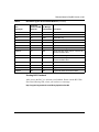
BCC Board Types: AN and ANH Modules ................................................. 13
BCC Board Types: BLN and BCN Modules ............................................... 14
HSSI Net Module Bandwidth Capacity ..................................................... 17
Standards Supported by Version 12.00 .................................................... 41
Approved Flash Memory Cards ................................................................ 46
ix
Technical Support
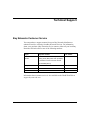
Bay Networks Customer Service
You can purchase a support contract from your Bay Networks distributor or
authorized reseller, or directly from Bay Networks Services. For information
about, or to purchase a Bay Networks service contract, either call your local Bay
Networks field sales office or one of the following numbers:
Region
Telephone number
Fax number
United States and
Canada
800-2LANWAN; then enter Express
Routing Code (ERC) 290, when prompted,
to purchase or renew a service contract
978-916-3514
978-916-8880 (direct)
Europe
33-4-92-96-69-66
33-4-92-96-69-96
Asia/Pacific
61-2-9927-8888
61-2-9927-8899
Latin America
561-988-7661
561-988-7550
Information about customer service is also available on the World Wide Web at
support.baynetworks.com.
117400-A Rev. A
xi
Release Notes for BayRS Version 12.00
How to Get Help
If you purchased a service contract for your Bay Networks product from a
distributor or authorized reseller, contact the technical support staff for that
distributor or reseller for assistance.
If you purchased a Bay Networks service program, call one of the following Bay
Networks Technical Solutions Centers:
xii
Technical Solutions Center
Telephone number
Fax number
Billerica, MA
800-2LANWAN
978-916-3514
Santa Clara, CA
800-2LANWAN
408-495-1188
Valbonne, France
33-4-92-96-69-68
33-4-92-96-69-98
Sydney, Australia
61-2-9927-8800
61-2-9927-8811
Tokyo, Japan
81-3-5402-0180
81-3-5402-0173
117400-A Rev. A
Release Notes for
BayRS Version 12.00
This document contains the latest information about Bay Networks®
Router Software Version 12.00.
These release notes include information about
•
Upgrading to Version 12.00
•
New Features
•
New Guidelines for Working with Version 12.00
•
Guidelines from Previous BayRS Releases
•
Protocols Supported
•
Standards Supported
•
Flash Memory Cards Supported
Upgrading to Version 12.00
To upgrade BayRS to Version 12.00, or to upgrade your Site Manager software to
Version 6.00, refer to Upgrading Routers from Version 7-10.xx to Version 12.00,
also in your upgrade package.
117400-A Rev. A
1
Release Notes for BayRS Version 12.00
New Features
Bay Networks has implemented the following new features in Version 12.00.
The Bay Command Console (BCC)
The BCC™ is replacing the trial versions released with Versions 11.02 and 11.01.
It includes the following new features:
•
Support for TCL script commands
•
Verb first parser
For example, we changed the command <object> disable to
disable <object>
•
Support for the ARE1 processor card
•
Improved online Help
•
BCC instructions in the protocol-specific manuals
Refer to “Using the BCC” on page -10 for guidelines.
IP Services
We have added the following new features to the IP services software.
Multicast OSPF
Multicast OSPF (MOSPF, RFC 1584) enables routers to route IP multicast
datagrams. The OSPF routing protocol determines the path for a unicast datagram
based on the datagram’s destination address only. The MOSPF protocol
determines paths based on the source and the multicast destination addresses of
the datagram. MOSPF also supports
•
Inter-AS multicast routing with DVMRP
•
Announce policies
1. The BCC runs on ARE processor cards to let you configure the protocols and interfaces listed later in this
document. However, the BCC does not support ATM.
2
117400-A Rev. A
Release Notes for BayRS Version 12.00
To configure Multicast OSPF, refer to “Guidelines for Configuring IP
Multicasting and Multimedia Services” on page -22 and Configuring IP
Multicasting and Multimedia Services.
Quality of Service Extensions to OSPF
For inter-area and intra-area multicast routing, Quality of Service extensions to
OSPF (QOSPF) works with the Resource Reservation Protocol (RSVP) and
Circuit Resource Management (CRM) to specify, request, and reserve resources.
RSVP stipulates traffic characteristics. QOSPF determines the dataflow paths
based on what it learns about traffic characteristics, network topology, and
resource information over the entire domain.
To configure QOSPF extensions, refer to “Guidelines for Configuring IP
Multicasting and Multimedia Services” on page -22 and Configuring IP
Multicasting and Multimedia Services.
New DVMRP Features
The new features for DVMRP include
117400-A Rev. A
•
Default route, including route listening, propagation, and generation.
•
An interface to the Multicast Table Manager (MTM), which facilitates
multicast data forwarding.
•
Interaction with the MOSPF protocol. To configure the new DVMRP features,
refer to “Guidelines for Configuring IP Multicasting and Multimedia
Services” on page -22 and Configuring IP Multicasting and Multimedia
Services.
•
Announce policies.
3
Release Notes for BayRS Version 12.00
Multicasting Tools
The following multicast tools are available for troubleshooting various types of
multicast networks:
•
mrinfo displays the capabilities of a DVMRP multicast router, indicates
whether it supports mtrace and pruning, and shows revision information. It
also shows the link characteristics for every link on the router.
•
mtrace traces multicast branches and displays statistics about packet rates
and losses for each hop along the path.
See Appendix B of Configuring IP Multicasting and Multimedia Services.
RSVP
The Resource Reservation Protocol (RSVP) allows host systems in an IP network
to reserve resources on RSVP-capable routers for unicast and multicast dataflows.
A dataflow is a transmission of packets requiring a certain quality of service
(QoS) from one or more sources to one or more destinations. BayRS Version
12.00
•
Supports RSVP as described in RFC 2205, Resource ReSerVation Protocol
(RSVP) -- Version 1 Functional Specification
•
Includes the Circuit Resource Manager (CRM) for support of RSVP
•
Interfaces to both unicast and multicast routing
To configure RSVP, refer to “Guidelines for Configuring IP Multicasting and
Multimedia Services” on page -22 and Configuring IP Multicasting and
Multimedia Services
MTM
Multicast Table Manager (MTM) is an application that manages multicast
protocols, executes the Internet Group Management Protocol (IGMP), maintains a
multicast forwarding cache, and forwards multicast traffic. MTM also supports
static multicast forwarding policies. IGMP supports accept policies.
To configure MTM and IGMP, refer to
4
•
“Guidelines for Configuring IP Multicasting and Multimedia Services” on
page -22
•
Configuring IP Multicasting and Multimedia Services
117400-A Rev. A
Release Notes for BayRS Version 12.00
•
Release Notes for Site Manager Software Version 6.00 to configure the IGMP
and MTM policy filter parameters
IPv6
Internet Protocol Version 6 (IPv6) supports large hierarchical addresses,
expanding to 128 bits. IPv6 also includes support for RIP (including accept and
announce policies), Neighbor Discovery, and traffic filters. To configure IPv6,
refer to
•
“Configuring IPv6” on page -20
•
Release Notes for Site Manager Software Version 6.00
•
Configuring IPv6 Services
IPv6 PPP Control Protocol
IPv6 PPP Control Protocol (CP) lets IPv6 operate over leased PPP lines. Using
this protocol, IPv6 negotiates for interface tokens to form link-local addresses.
This protocol supports agreement or disagreement between PPP peers as to
whether they can exchange IPv6 datagrams over the PPP link. To enable this
protocol, refer to Configuring PPP Services.
ISP Mode
Internet Service Provider mode comprises features that make a router more
efficient in an Internet service provider environment. These features include BGP
soloist (BGP running on only one slot on a router), cache elimination, and
memory allocation suitable for accommodating large routing tables. To configure
ISP mode, refer to Configuring IP Services.
Network Address Translation (NAT)
NAT maps a local, unregistered source IP address in an outgoing packet to a
registered address recognizable by the rest of the network world. The mapping
enables two or more networks to communicate without changing IP addresses in
their own networks, even if there are duplicate IP addresses across the networks.
The mapping occurs dynamically. To configure NAT, refer to Configuring IP
Services.
NAT does not support FTP applications.
117400-A Rev. A
5
Release Notes for BayRS Version 12.00
X.25 Gateway and X.25 PVCs
Version 12.00 supports X.25 PVCs for X.25 Gateway services only.
X.25 Gateway provides connectivity between X.25-based terminal users and
applications running on TCP/IP-based hosts. Using this software, a router
translates data received from X.25 virtual connections into TCP data and forwards
it through TCP connections and vice versa. The terminals may be connected to the
router by a leased line, an X.25 packet-switched network, or a T1/E1-based
circuit-switched network. An X.25 permanent virtual circuit (PVC) is a permanent
translation stream that remains up until one peer terminates it, or X.25 resets or
restarts. PVCs are a standard feature of X.25 software.
Asynch over TCP
The Asynch over TCP (AOT) software routes asynchronous traffic polled from
alarm hosts to alarm devices over a TCP/IP backbone. It is also called the Polled
Asynch Protocol (PAS) or Asynch Passthru over TCP. This software runs on the
following platforms and I/O modules:
•
ASN™ -- Dual Sync net module and Quad Sync net module
•
AN®
•
ARN™
•
BN® -- Octal Sync link module
Router Redundancy
Router redundancy now includes an attribute, wfRRedundWarmBoot, in the
wfRRedundGroup object that allows router redundancy to operate among routers
running BayRS Version 11.01 and later, or 11.00 and earlier. This attribute is
accessible only via the Technician Interface.
Caution: Use the same wfRRedundWarmBoot setting for all routers in a router
redundancy group.
If all of the routers in a router redundancy group are running Version 11.01 and
later, use the default setting, disabled, to allow a router in the group to perform a
role switch without rebooting.
6
117400-A Rev. A
Release Notes for BayRS Version 12.00
If the routers in a router redundancy group are running Version 11.01 or later, and
Version 11.00 or earlier, a router in the group must reboot to perform a role
switch. Enter the following Technician Interface command to enable booting for
every router in the group:
set wfRRedundGroup.31.0 <value>;commit
31 represents the wfRRedundWarmBoot attribute.
0 represents the router instance.
value is 1 (enabled) or 2 (disabled).
Frame Relay Traffic Shaping
Frame relay traffic shaping provides a more flexible mechanism to control
congestion per VC than our former method, which dropped traffic destined for a
PVC where there was congestion.
Traffic shaping provides the ability to throttle (queue) congested traffic rather than
drop it, or to throttle congested traffic, and then shut down the VC if congestion
continues. Committed information rate (CIR) enforcement and quality of service
(QoS) determine how traffic shaping works.
The CIR is the rate at which the network supports data transfer under normal
conditions; you negotiate this value with your carrier. You can configure frame
relay to restrict the speed of outbound traffic to a rate no faster than the CIR, and
this is called CIR enforcement. You can also manipulate several variables to send
data faster than the CIR when there is no congestion.
QoS adds protocol prioritization to traffic shaping. This creates two types of
queues for outbound traffic, with shaped traffic having a higher priority than
normal traffic.
For instructions on configuring traffic shaping, refer to Configuring Frame Relay
Services.
117400-A Rev. A
7
Release Notes for BayRS Version 12.00
SRB over ATM PVCs
The Source Route Bridge (SRB) protocol over ATM permanent virtual circuits
(PVCs) enables frame relay to more readily interoperate with ATM (by running
SRB in the ATM WAN network). You can configure the same SRB parameters
available for frame relay and token ring (in both standard SRB and Bay Networks
proprietary formats).
BaySecure FireWall-1
BaySecure™ FireWall-1 integrates Version 2.1 of Check Point Software
Technologies Ltd™ FireWall-1™ software, with the exception of user
authentication, address translation, statistics, and encryption features, into the Bay
Networks GAME router operating system. Through this integration, Bay
Networks routers provide fully secure, bidirectional, anti-spoofing
communication for all Internet applications and services, such as FTP, Telnet, and
SMTP.
BaySecure FireWall-1 supports the following interfaces:
•
Wellfleet Standard
•
Frame relay (group mode only)
•
Ethernet
For instructions, refer to “Configuring and Managing BaySecure FireWall-1” on
page -28 and Configuring BaySecure Firewall-1.
DVMRP Cache Command
The Technician Interface ip dvmrp_caches -s command obtains DVMRP routing
caches for the slot you specify. This command replaces the ip cache -M
command. For more information about this and other changes to the ip command,
refer to Using Technician Interface Software.
8
117400-A Rev. A
Release Notes for BayRS Version 12.00
Support for HSSI Net Module in the ASN and System 5000
Version 12.00 supports the Single HSSI net module (SHSSINM 3584), including
loopback testing, on the ASN and System 5000. For instructions, refer to
•
“Using the HSSI Net Module in a Stand-Alone ASN” on page -16
•
Installing a HSSI Net Module in an ASN Platform or Installing a HSSI Net
Module in a System 5000
•
Configuring WAN Line Services
New Guidelines for Working with Version 12.00
Note the following new guidelines when using Version 12.00. They supplement
the instructions in the 12.00 documentation set.
Upgrading Routers from Version 7-11.xx to Version 12.00
The following sections correct the instructions in Upgrading Routers from Version
7-11.xx to Version 12.00.
Locating the BCC Help File on the CD
The first paragraph under “Using the BCC Help File” on page 2-9 of
Upgrading Routers from Version 7-11.xx to Version 12.00 incorrectly states that
the bcc.help file is in the rel directory of the upgrade CD. It is actually named
bcc_help, and it is in the same directory as the boot image in the upgrade CD.
Renaming the BCC Help File after Loading the Router Software
onto a PC
After following the instructions in “Loading the Router Software onto a PC” on
page 3-7 of Upgrading Routers from Version 7-11.xx to Version 12.00, rename
the bcc_help file to bcc.help.
117400-A Rev. A
9
Release Notes for BayRS Version 12.00
Using the BCC
Before Using the BCC
The BCC is a command-line interface for configuring Bay Networks devices. It
also supports Technician Interface commands and scripts.
Before using the BCC, refer to the following sections listing the platforms,
protocols, and interfaces that the BCC supports.
Platforms Supported
The BCC runs on AN, ANH1, and BN platforms including both ARE2 and FRE®
processor cards. Each slot must have
•
8 MB of dynamic RAM (DRAM)
•
1.5 MB of free memory space
If you try to start the BCC with insufficient DRAM or free memory on a slot, the
BCC returns an error message. In that case, use Site Manager instead of the BCC.
Global Protocols Supported
You can use BCC commands to configure the following global protocols:
BCC supports the following
•
IP (including access policies and static routes)
•
ARP
•
OSPF (including accept and announce policies)
•
BGP (including accept and announce policies)
•
IGMP
•
RIP (including accept and announce policies)
•
Telnet
1. You cannot use BCC commands to configure the operation of any ISDN, DCM, or CSU/DSU daughterboard
in an AN or ANH device. (Use Site Manager to configure these daughterboards.)
2. The BCC runs on ARE processor cards to let you configure the protocols and interfaces listed in this section.
However, the BCC does not support ATM.
10
117400-A Rev. A
Release Notes for BayRS Version 12.00
•
TFTP
•
FTP
•
NTP
•
SNMP
Interface Protocols Supported
You can use BCC commands to configure the following interface protocols:
•
IP
•
ARP
•
IGMP
•
RIP
•
OSPF
•
Router Discovery (RDISC)
•
Proprietary Standard Point-to-Point
•
PPP (certain line parameters only)
Refer to Configuring PPP Services for details.
Interfaces Supported
You can use BCC commands to configure the following interfaces:
•
Console
•
Ethernet
•
Token ring
•
Synchronous
•
FDDI
•
HSSI
•
Virtual
Tables 1 and 2 on pages -13 and -14 list the link and net modules BCC supports.
117400-A Rev. A
11
Release Notes for BayRS Version 12.00
Getting Started
Caution: BCC configuration and source commands make immediate changes
to the active device configuration. Read about the source command in Using
the Bay Command Console (AN/BN Routers).
Before using the BCC, we recommend that you save your configuration files by
copying them onto the same Flash memory card using new file names.
To start BCC, enter bcc at the Technician Interface prompt of a Model AN, ANH,
BCN®, or BLN® router.
Enter help learning-bcc at the bcc> prompt to display the online instructions for
new BCC users. Then enter help -more to display a full summary of the
Help-oriented features of the BCC interface.
For more general information about how to use the BCC interface, refer to Using
the Bay Command Console (AN/BN Routers).
For instructions on using the BCC to add and customize specific services, refer to
the appropriate customizing services guide.
Configuring BCC
This section supplements the instructions in Using the Bay Command Console
(AN/BN Routers)
Only one BCC session can be active at a time.
If you use the BCC show config command to view a router’s configuration, BCC
displays only the protocols it supports. Before using the BCC to delete an
interface, make sure that you did not use Site Manager to configure it with an
unsupported protocol. If you did, use Site Manager to delete the interface.
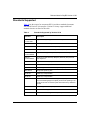
Identifying Board Types
This section supplements the instructions in the documentation set.
Tables 1 and 2 identify the Board Type parameter values displayed by BCC. Use
the “Board Type” column to identify a hardware module in an AN or BN router
configuration.
12
117400-A Rev. A
Release Notes for BayRS Version 12.00
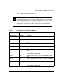
Table 1 lists the AN and ANH board types.
Note: You can use BCC commands to configure any AN or ANH device, but
note the following exception: You cannot use BCC commands to configure the
operation of any ISDN, DCM, or CSU/DSU daughterboard in an AN or ANH
device. (Use Site Manager to configure these daughterboards.) Inserting a
daughterboard into an AN base module redefines its module ID and board
type.
Table 1.
BCC Board Types: AN and ANH Modules
BCC Board Type
Technician
Interface or MIB
Module ID
Description
andeds
1033
AN-ENET (2 Ethernet ports, 2 sync ports) with 8 MB or 16 MB
DRAM
andedsg
1050
ANH-8 (2 Ethernet ports, 2 sync ports) with 8 MB or 16 MB
DRAM and an 8-port Ethernet hub active for the first Ethernet
port
andedsh
1035
ANH-12 (2 Ethernet ports, 2 sync ports) with 8 MB or 16 MB
DRAM and a 12-port Ethernet hub
andedst
1034
AN-ENET (2 Ethernet ports, 2 sync ports, 1 token ring port) with
8 MB or 16 MB DRAM
andst
1037
AN-TOKEN (2 sync ports, 1 token ring port) with 8 MB or 16 MB
DRAM
ansdsedst
1041
AN-ENET/TOKEN (1 Ethernet port, 2 sync ports, 1 token ring
port) with 8 MB or 16 MB DRAM
anseds
1024
AN-ENET (1 Ethernet port, 2 sync ports) with 8 MB or 16 MB
DRAM
ansedsg
1047
ANH-8 (1 Ethernet port, 2 sync ports) with 8 MB or 16 MB DRAM
and an 8-port Ethernet hub
ansedsh
1026
ANH-12 (1 Ethernet port, 2 sync ports) with 8 MB or 16 MB
DRAM and a 12-port Ethernet hub
ansedst
1025
AN-ENET/TOKEN (1 Ethernet port, 2 sync ports, 1 token ring
port) with 8 MB or 16 MB DRAM
(continued)
117400-A Rev. A
13
Release Notes for BayRS Version 12.00
Table 1.
BCC Board Types: AN and ANH Modules (continued)
BCC Board Type
Technician
Interface or MIB
Module ID
Description
ansets
1030
AN-ENET (1 Ethernet port, 3 sync ports) with 8 MB or 16 MB
DRAM
ansetsg
1049
ANH-8 (1 Ethernet port, 3 sync ports) with 8 MB or 16 MB DRAM
and an 8-port Ethernet hub
ansetsh
1032
ANH-12 (1 Ethernet port, 3 sync ports) with 8 MB or 16 MB
DRAM and a 12-port Ethernet hub
ansetst
1031
AN-ETS (1 Ethernet port, 3 sync ports, 1 token ring port) with
8 MB or 16 MB DRAM
antst
1039
AN-TOKEN (3 sync ports, 1 token ring port) with 8 MB or 16 MB
DRAM
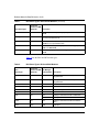
Table 2 lists the BLN and BCN board types.
Table 2.
BCC Board Types: BLN and BCN Modules
BCC
Board Type
Technician
Interface or MIB Site Manager
Module ID
Model Number Description
comp
4353
AG2104037
Octal Sync with 32-context compression
daughterboard
comp128
4354
AG2104038
Octal Sync with 128-context compression
daughterboard
de100
4864
50038
100BASE-T Ethernet
dst416
40
5740
Dual Sync with token ring
dtok
176
5710
Dual token ring
enet3
132
5505
Dual Ethernet
esaf
236
5531
Dual Sync Dual Ethernet with 2-CAM filters
5532
Dual Sync Dual Ethernet with 6-CAM filters
esafnf
232
5431
Dual Sync Dual Ethernet without hardware
filters
osync
4352
5008
Octal Sync
(continued)
14
117400-A Rev. A
Release Notes for BayRS Version 12.00
Table 2.
BCC Board Types: BLN and BCN Modules (continued)
BCC
Board Type
Technician
Interface or MIB Site Manager
Module ID
Model Number Description
qef
164
5950
Quad Ethernet with hardware filters
qenf
162
5450
Quad Ethernet without hardware filters
qtok
256
50021
Quad token ring
shssi
225
5295
HSSI
sse
118
5410
Single Sync with Ethernet
sync
80
5280
Quad Sync
wffddi1m
193
5943
Hybrid FDDI with single mode on connector B
wffddi1mf
197
5949
Hybrid FDDI with single mode on connector B,
and with hardware filters
wffddi1s
195
5942
Hybrid FDDI with single mode on connector A
wffddi1sf
199
5948
Hybrid FDDI with single mode on connector A,
and with hardware filters
wffddi2m
192
5930
Multimode FDDI
wffddi2mf
196
5946
Multimode FDDI with hardware filters
wffddi2s
194
5940
Single Mode FDDI
wffddi2sf
198
5947
Single Mode FDDI with hardware filters
Sending BCC Feedback
After you use the BCC, we welcome your feedback. Please visit the BCC Web
Site at the following URL, where you can leave us a message:
http://support.baynetworks.com/library/tpubs/bccfeedbk
117400-A Rev. A
15
Release Notes for BayRS Version 12.00
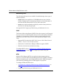
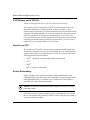
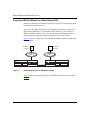
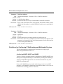
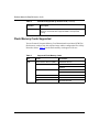
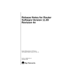
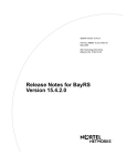
Using the HSSI Net Module in a Stand-Alone ASN
Because a stand-alone (non-stacked) ASN has a single CPU, multiple high-speed
interfaces place a high load on it.
You can use the HSSI net module with other high-speed interfaces, such as the
FDDI and/or 100BASE-T, in a stand-alone ASN. However, if you configure a
HSSI net module to achieve T3 or OC-1 speeds, the forwarding performance is
limited, especially with other high-speed interfaces in the same chassis.
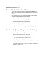
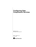
Figure 1 shows two ASNs, each with a FDDI and HSSI net module, passing traffic
bidirectionally.
Sends traffic Host
to Host B
A
FDDI
rings
Host Sends traffic
to Host A
B
FDDI
rings
FDDI net module
FDDI net module
HSSI net module
HSSI net module
ASN 1
Figure 1.
ASN 2
HSSI Net Module Test in Stand-Alone ASNs
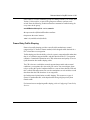
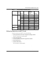
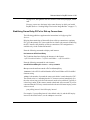
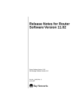
Table 3 shows the bandwidth capacity of the HSSI link between the two ASNs in
Figure 1.
16
117400-A Rev. A
Release Notes for BayRS Version 12.00
Table 3.
HSSI Net Module Bandwidth Capacity
PVCs or
Circuits Packet Size
Maximum
Packets Per
Second
Without Loss
Effective
Throughput
1
64
9500
4.86 Mb
50
64
5000
2.56 Mb
1
512
6500
26.62 Mb
50
512
5000
20.48 Mb
1
64
9500
4.86 Mb
50
64
6000
3.07 Mb
1
512
7000
28.67 Mb
50
512
5500
22.53 Mb
NA
1
64
18,300
9.37 Mb
NA
1
512
11,000
45.06 Mb
NA
1
64
18,200
9.32 Mb
NA
1
512
10,800
44.24 Mb
WAN Protocol
Direct
or
Group
Frame Relay
direct
group
PPP
Wellfleet
Standard
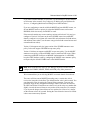
Editing Line Resources on an MCT1 Circuit
To edit line resources on an MCT1 circuit do the following:
1.
Click on the MCT1 circuit in the configuration manager window.
The MCT1 Logical Lines window appears.
2.
Click on the logical line.
3.
Scroll to the bottom of the MCT1 Logical Lines window.
4.
Select Line Resources.
5.
Click the Values button.
The Line Resources window appears.
117400-A Rev. A
17
Release Notes for BayRS Version 12.00
Corrections to Configuring PPP Services
The following sections identify corrections to Configuring PPP Services.
Configuring PPP over Dial-up Lines
The check mark in the BCC column next to “Run PPP over dial-up lines” in
the table on Page 1-2 of Configuring PPP Services is incorrect. You must use Site
Manager to configure PPP over dial-up lines.
Using the BCC to Start PPP Services
The following instructions replace those in “Using the BCC” on page 1-4 of
Configuring PPP Services:
To enable IP routing on a given interface, navigate to the IP prompt by entering
the commands shown in bold in the following sequence.
1.
Specify the physical interface on which to enable IP routing.
box# <connection_type> slot <slot_no.> connector <connector_no.>
Connection_type can be sync or hssi.
Slot_no. and connector_no. indicate the slot number and connection number
on which to enable IP routing; for example,
box# sync slot 3 connector 1
2.
Configure PPP on this interface.
sync/3/1# ppp
3.
Configure the IP address and mask for this interface.
ppp/3/1# ip address <IP_address> mask <subnet_mask>
For example, the following command assigns an IP address of 1.1.1.1 with a
standard Class C mask.
ppp/3/1# ip address 1.1.1.1 mask 255.255.255.0
When you configure the IP address and subnet mask, the router automatically
enables IP services.
18
117400-A Rev. A
Release Notes for BayRS Version 12.00
Using the BCC to Enable PPP on an Interface
The prompt is incomplete in the example under “Using the BCC” on page 3-3 of
Configuring PPP Services. The prompt in the following sample command is
correct:
ip/1.1.1.1/255.255.255.0# state enable
Using the BCC to Disable a Network Control Protocol
The prompt is incomplete in the example under “Using the BCC” on page 3-14 of
Configuring PPP Services. The prompt in the following sample command is
correct:
ip/1.1.1.1/255.255.255.0# state enable
Using the BCC to Force LCP Renegotiation
To force LCP renegotiation on a given line, enter the commands shown in bold in
the following sequence.
1.
Specify the physical line on which to force LCP renegotiation.
box# <connection_type> slot <slot_no.> connector <connector_no.>
Connection_type can be sync or hssi.
Slot_no. and connector_no. indicate the slot number and connection number;
for example,
box# sync slot 3 connector 1
2.
Disable the line.
sync/3/1# state disable
3.
Reenable the line.
sync/3/1# state enable
117400-A Rev. A
19
Release Notes for BayRS Version 12.00
Adding X.25 Logical Lines and X.25 Service Entries
If you use dynamic mode to add an X.25 logical line or add an X.25 service entry,
save the changes to the configuration file on the Flash memory card and boot the
router for the changes to take effect.
Configuring IPv6
This description supplements those in Configuring IPv6 Services.
Version 12.00 does not support
•
BCC configuration of IPv6
Use Site Manager to configure IPv6.
•
IPv6 over frame relay or X.25 PDN
•
IPv6 over hashed source/destination multiline
Use the round robin option.
•
IPv6 over PPP on VME platforms
•
Priority queueing of IPv6 traffic
Caution: Set the RIP diameter of every IPv6 interface on the router to the
same value. Use Site Manager to set the RIP diameter. See Configuring IPv6
Services, “Specifying the RIPv6 Diameter.”
The following parameter descriptions provide more information than the Site
Manager parameter online Help and pages A-4 and A-5 of Configuring IPv6
Services.
20
117400-A Rev. A
Release Notes for BayRS Version 12.00
Parameter: Interface Token
Path: Configuration Manager > Protocols > IPv6 > Edit IPv6 Interfaces
Default: See Instructions.
Options: A portion of an IPv6 address, consisting of 0 to 32 hexadecimal characters,
delimited with a colon (:) every four hexadecimal characters.
Function: Supplies an identifier (an interface token) for this interface that is unique on the
link to which this interface is attached. The interface token is combined with an
address prefix to form an interface address.
Instructions: If you do not configure a token, the router automatically configures it according
to the rules of the link type to which this interface is attached. For most media,
this involves mapping the link layer (or MAC) address, X.121 address, or other
system unique value (e.g. serial number) to a 64-byte value. (For example, MAC
Address 00-00-a2-11-22-33 maps to IPv6 Token Address 0200:a2ff:fe11:2233).
MIB Object ID: 1.3.6.1.4.1.18.3.5.3.16.1.1.2.1.7
Parameter: Circuit Name
Path:
Default:
Options:
Function:
Configuration Manager > Protocols > IPv6 > Edit IPv6 Interfaces
The name of the circuit on which you have configured the IPv6 interface
A valid circuit name
Identifies the circuit that the interface runs over.
Zero indicates that this is a tunnel end point. In IPv6 tunneling, IPv6 packets are
encapsulated and transmitted by another network layer protocol or another
instance of the IPv6 protocol. A value of 1023 or greater indicates a circuitless
or software loopback, IPv6 interface.
Instructions: Supply a value that identifies this circuit.
MIB Object ID: 1.3.6.1.4.1.18.3.5.3.16.1.1.2.1.6
117400-A Rev. A
21
Release Notes for BayRS Version 12.00
Parameter: Link Layer Address
Path:
Default:
Options:
Function:
Instructions:
Configuration Manager > Protocols > IPv6 > Edit IPv6 Interfaces
None
A valid link layer address
Specifies the link layer or Layer 2 frame address for this IPv6 interface
Supply a link layer address in the correct format. For Ethernet, FDDI, or token
ring, the link layer address is a 48-bit IEEE 802.3 media access control (MAC)
address.
MIB Object ID: 1.3.6.1.4.1.18.3.5.3.16.1.1.2.1.11
Parameter: Slot Mask
Path:
Default:
Options:
Function:
Instructions:
Configuration Manager > Protocols > IPv6 > Edit IPv6 Interfaces
4294705152
All slots
Specifies which slots a circuitless interface is eligible to run on.
Select one or more slots as candidates to run this circuitless IPv6 interface. This
parameter is relevant only if the Circuit Name parameter for this IPv6 interface
is set to a value greater than 1023.
MIB Object ID: 1.3.6.1.4.1.18.3.5.3.16.1.1.2.1.15
Guidelines for Configuring IP Multicasting and Multimedia Services
The following guidelines supplement the instructions in Configuring IP
Multicasting and Multimedia Services.
Configuring MOSPF, QOSPF, and DVMRP
Version 12.00 does not support dynamic configuration of MOSPF/QOSPF. After
making local configuration changes, restart OSPF by disabling and reenabling it.
Version 12.00 QOSPF supports inter-area and intra-area multicast only with
RSVP FF reservation style.
If you enable MOSPF, do not run other multicasting protocols on any OSPF
interfaces, even if MOSPF is disabled on those interfaces (that is, even if you set
the Multicast Forwarding parameter to blocked).
22
117400-A Rev. A
Release Notes for BayRS Version 12.00
If you want to disable MOSPF on a network, use Site Manager to disable MOSPF
on all routers in the network. See Configuring IP Multicasting and Multimedia
Services, “Configuring Multicast Forwarding on an OSPF Interface.”
If you are configuring a network with both MOSPF and non-MOSPF routers, set
all non-MOSPF routers to priority 0 so that the MOSPF routers can become
DR/BDR, which is necessary for MOSPF to work.
If the network contains any routers running versions earlier than 12.00, and you
configure a Version 12.00 router to advertise DVMRP routes into an MOSPF
domain, configure it to originate AS external link advertisements for both unicast
and multicast routes (that is, use the same entry point for both external unicast and
external multicast routes).
Version 12.00 supports only the ignore action of the DVMRP announce route
policy. It does not support a DVMRP accept route policy.
Version 12.00 does not support an MOSPF accept route policy. Use the MOSPF
announce route policy to import DVMRP routes as multicast ASE routes. When
connecting an MOSPF domain to an MBONE implementation via a DVMRP,
keep the OSPF database small by configuring the MOSPF route announce policy
to import only the default DVMRP route to the MOSPF domain.
Note: Refer to the Release Notes for Site Manager Software Version 6.00 to
configure the DVMRP, MOSPF, IGMP, and MTM policy filter parameters.
We recommend that you avoid using MOSPF in a transit domain for multicast.
The router will time out an MOSPF forwarding entry a certain time after it
receives the last packet in the flow. The default timeout value is 600 seconds. You
can change this value by setting the Timeout Value parameter. To access this
parameter, begin at the Configuration Manager window, and click on Protocols,
IP, OSPF, and Global. If most flows are short-lived, set the value to a number that
slightly exceeds the interval between two packets of the same flow. For example,
if you expect the longest interval between two packets for a flow to be 1 minute,
set the timeout value to 90 seconds. Setting the value below the interval is OK but
it does cause unnecessary Dykstra.
117400-A Rev. A
23
Release Notes for BayRS Version 12.00
Monitoring MOSPF
On a router running both MOSPF and DVMRP, the following values indicate an
external upstream interface (that is, a DVMRP interface):
•
The Upstream Interface value 255.255.255.254 appears when you enter the
Technician Interface show mospf fwd command.
•
The in value -2 appears when you enter the Technician Interface ip
mospf_fwd command.
Monitoring DVMRP
The dvmrp.bat script has changed as follows because DVMRP no longer forwards
data:
•
The Technician Interface does not display In Drops and Out Drops statistics in
response to the show dvmrp stats circuits command.
•
The Technician Interface does not display In Packets, Out Packets, Ip Drop,
Out Drop, and Thrshld Drop statistics in response to the show dvmrp stats
vifs command.
Configuring the Expanding Ring Search
The support for Expanding Ring Search in MOSPF is disabled by default for
better performance. You can use Site Manager to enable it. See Configuring IP
Multicasting and Multimedia Services, “Enabling Dynamic TTL.”
Configuring Administratively Scoped Multicast
Packets with administratively scoped multicast addresses are locally assigned, and
are not required to be unique across administrative boundaries because they do not
cross them. Refer to the Internet Draft Administratively Scoped IP Multicast
(draft-ietf-mboned-admin-ip-space-03.txt) for details.
Version 12.00 does not support the dynamic configuration of administratively
scoped multicast. Site Manager also does not support it. Use the Technician
Interface to configure it via the wfIgmpBoundaryEntry MIB object.
24
117400-A Rev. A
Release Notes for BayRS Version 12.00
Configuring the Static Forwarding Entry
Version 12.00 does not support the dynamic configuration of the multicast Static
Forwarding Entry. Refer to “MTM Static Forwarding Policy Parameters” in the
Release Notes for Site Manager Software Version 6.00 to control the forwarding
of multicast packets.
Static forwarding entries statically determine how the router forwards particular
multicast flows. You can not use both static and dynamic (via multicast protocols)
forwarding. For example, you can not configure a static forwarding entry to
specify that for a particular source/group pair, the router accept packets on
Circuit 1, forward them out Circuits 2 and 3, but rely on a multicast protocol to
dynamically decide if those packets should be forwarded out Circuit 4.
Configuring the DVMRP Prune Lifetime
By default, DVMRP sets a lifetime of 7200 seconds on the prune messages it
sends out an interface. You can use Site Manager to specify a lifetime between 0
and 86,400 seconds.
Beginning at the Configuration Manager window, click on Protocols and IP. The
IP protocol menu appears. Click on Multicast, DVMRP, and Circuit. The DVMRP
circuit window opens. Set the Prune Life Time parameter and click on Done.
Configuring Multicasting Policies
You can use Site Manager to configure routing policies for DVMRP, MOSPF,
IGMP, and MTM.
Beginning at the Configuration Manager, click on Protocol and IP. The IP protocol
menu appears. Click on Policy Filters and select the multicasting protocol for
which you want to configure a policy. A protocol-specific window for the policy
opens. Set the parameters to define the policy and click on Done.
117400-A Rev. A
25
Release Notes for BayRS Version 12.00
Enabling BAP for Bandwidth-on-Demand Service
The procedures for enabling the bandwidth allocation protocol (BAP) and the
names of the BAP parameters changed after the publication of Configuring Dial
Services.
BAP is no longer an option on the Select Protocols menu. The BAP parameters,
Enable BAP and BAP No Phone Number Needed, are in
•
The Bandwidth On Demand Monitor Options window.
To open this window, refer to “Monitoring Congestion on the Bandwidth or
Demand Circuit” in Chapter 11 of Configuring Dial Services.
•
The BOD Configuration window for demand circuits.
To open this window, refer to “Adding Bandwidth Service for Demand Lines”
in Chapter 1 of Configuring Dial Services.
For BAP parameter descriptions, refer to Appendix A of Configuring Dial
Services. The parameter names in the appendix are Enable and No Phone Number
Needed.
Corrections to Configuring and Managing Routers with Site Manager
Note the following corrections to Configuring and Managing Routers with Site
Manager:
•
On page 6-8, the text that follows step 5 should read:
The directory and file name that you specify depend on the following:
•
The computer platform (UNIX workstation or PC)
•
The type of router
If you loaded BayRS onto a UNIX workstation, the image is in the directory
for the type of router. For example, the image bn.exe for the BN router is in
the directory for the BN.
If you loaded BayRS onto a PC, the image is in the directory you created for
the image, for example, \wf\xxx.
26
117400-A Rev. A
Release Notes for BayRS Version 12.00
•
On page 6-14, disregard the first two sentences of the third paragraph, which
read:
You may want to save the image in the same directory in which you loaded
BayRS. (Refer to “Loading Image Files into the Image Builder” on page 6-7.)
Stabilizing Frame Relay PVCs for Dial-up Connections
The following guidelines supplement the instructions in Configuring Dial
Services.
Delaying the transmission of data traffic from a dial-up connection to a primary
PVC gives the primary PVC time to stabilize in a frame relay network. Stabilizing
the PVC increases the reliability of dial-up connections. The configuration is
available only via the Technician Interface.
Enter the following command to display each instance:
list instances wfFrVCircuitEntry
The Technician Interfaces displays the instances in the format
<wfFrCircuitLineNumber>.<wfFrCircuitLLIndex>.<wfFrCircuitDlci>.
Enter the following command for each instance:
set wfFrVCircuitEntry.53.<instance> <delay>;commit
53 represents the attribute named wfFrCircuitStartupDelay.
<instance> is the wfFrCircuitLineNumber.wfFrCircuitLLIndex.wfFrCircuitDlci
character string.
<delay> is the number of seconds the router waits before it sends data to the PVC.
The default value is 0, indicating that the VC becomes activate immediately. Set
the value to how long you believe the network needs to be stabilized. Typically, it
is how long it takes for the status to match at both ends of the network. If you are
concerned that the PVC may come down before the next full status inquiry, set the
value to exceed
your polling interval * the full-inquiry interval
For example, if your polling interval is the default value 10, and the full-inquiry
interval is the default value 6, set the <delay> to exceed 60.
117400-A Rev. A
27
Release Notes for BayRS Version 12.00
Configuring OSPF on ARN routers
If you use the Technician Interface quick-start script (inst_arn.bat) to configure a
second IP interface with OSPF as the routing protocol on another serial interface
on an ARN router, the script prompts you for an OSPF router ID, and displays the
IP address you are configuring as the default address. Do not accept it. You
already entered an OSPF router ID for the initial serial interface. Because this
prompt is for a global address, assign the same router ID address to the second
serial interface.
Configuring and Managing BaySecure FireWall-1
The following guidelines supplement the instructions in Configuring BaySecure
FireWall-1.
Configuring FireWall-1
For proper firewall operation, perform these steps:
1.
Enable TCP on all slots on the router.
2.
Create an instance of a firewall using Site Manager:
a.
Configure a local host and log host IP address on the router.
b.
Enable FireWall-1 on all interfaces.
3.
Create a static route if the router and firewall management stations are
on different subnets.
4.
Reboot the router with a firewall configuration file.
5.
Synchronize the router and management station passwords by executing
the fwputkey command on both the router and the firewall management
station.
6.
Define a security policy and add a network object for the router using the
FireWall-1 GUI.
7.
Save the configuration and boot the router.
8.
Install the security policy on the router.
If you have performed these steps and still have system problems, contact the Bay
Networks Technical Solutions Center.
28
117400-A Rev. A
Release Notes for BayRS Version 12.00
Responding to Management Software Version Error When Installing a
Firewall-1 GUI Client Security Policy
If the Firewall-1 GUI Client displays a message stating the management software
is 2.x, not 3.0, follow these instructions to install the X/Motif GUI client:
Note: This FireWall-1 GUI client is not available for SunOS platforms.
1.
Log in as root.
2.
Mount the CD and extract the tar files, as follows:
cd /tmp
tar xvf /cdrom/<o_s>/gui-clnt/fwgui.<tarfile_name>.tar
3.
Run the installation script:
./fwguiinstall
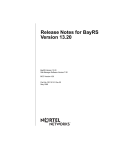
The following shows a sample installation. The user input is in bold. When
the script displays the thank you message, continue with the instructions on
page -30.
******FireWall-1 GUI client v3.0 Installation*******
please wait .....
Selecting FireWall-1 GUI client base directory
---------------------------------------------FireWall-1 GUI client requires approximately 26890 KB of free disk
space.
The FireWall-1 GUI client will be extracted into two subdirectories
('bin' and 'clients') of the base directory
Enter base directory [/etc/fw]):[RETURN]
Checking disk space availability...
Installing FW under /etc/fw (244651 KB free)
Are you sure (y/n) [y] ?[RETURN]
Software distribution extraction
-------------------------------Extracting software distribution. Please wait ...
Software Distribution Extracted to /etc/fw
117400-A Rev. A
29
Release Notes for BayRS Version 12.00
********** FireWall-1 GUI client Setup **************
FireWall-1 GUI client access and execution permissions
------------------------------------------Usually, FireWall-1 GUI client is given group permission for access
and execution.
You may now name such a group or instruct the installation procedure
to give no group permissions to FireWall-1 GUI client.
In the latter case, only you will be able to access and execute
FireWall-1 GUI client.
Please specify group name [<RET> for no group permissions]: other
Group other will be used. Is this ok (y/n) [y] ?[Y]
Setting Group Permissions...
**********************************************************
Thank you for using FW-1
To run the clients use /etc/fw/bin/{fwpolicy, fwlog, fwstatus}
*******************************************************
4.
Run the GUI:
# wfpolicy
5.
Enter your user id and password, and the management station that you
want to connect to.
Responding to Check Point FireWall-1 Errors
The Check Point FireWall-1 software may report the following errors. Follow the
instructions provided for resolving these errors.
30
Error:
Installing Security Policy nologs_fast.pf on all.all@BLN73 (Bay
Networks). Authentication for command bload failed. Failed to
Install Security Policy on BLN73: Unauthorized action
Meaning:
The router and management station passwords are no longer
synchronized because either a configuration change involved the log
host or local host IP addresses, or the FRE module was swapped out
since the putkey command was last executed.
Action:
Use the putkey command on both the router and the firewall
management station to synchronize the passwords. Once you resolve
this error, other configuration errors may appear.
117400-A Rev. A
Release Notes for BayRS Version 12.00
Error:
Installing Security Policy nologs_fast.pf on all.all@BLN73 (Bay
Networks). bload: connect(BLN73): Connection refused. Failed
to Install Security Policy on BLN73: Connection refused
Meaning:
The firewall management station and the router cannot establish a
channel of communication because either RFWALLC is not
initialized or TCP is not enabled on the slot where the network link
module is located, or the router is pointing to an incorrect log host IP
address.
Action:
Load TCP onto the slot where the network link module is located, and
verify that the log host IP address is correct. As long as you enable
TCP on all slots and a physical connection to the management station
exists, communication should be continuous.
Otherwise, you can force FWALLC to initialize on the slot where the
network link module is located, and verify that the log host IP address
is correct. To force FWALLC to initialize on a particular slot, place
the flash card that contains the configuration file in the desired slot.
However, if the slot goes down or is bounced, RFWALLC will be
forced onto another slot, and all communication with the
management station will be lost unless you have configured an
alternate route to the management station for a link module residing
on the new slot.
We suggest using circuitless IP to avoid the need for FWALLC to
reside on a particular slot.
117400-A Rev. A
Error:
Installing Security Policy nologs_fast.pf on all.all@BLN73 (Bay
Networks). Version 3.0 cannot load security policy on
192.168.135.79 because it is an earlier release (2.x). You must
upgrade the FireWall-1 software there in order to be able to
manage it from version 3.0 management station. Authentication
for command bload failed. Failed to Install Security Policy on
BLN73: Unauthorized action
Meaning:
This error occurs when the local host IP address is not set to the
firewalled router’s address. Although the error mentions an
authentication problem, this is not necessarily the case. The router
and management station may be synchronized.
31
Release Notes for BayRS Version 12.00
Action:
Set the local host IP address to the firewalled router’s address, save
the configuration, and reboot the router.
If the Log Host IP Address parameter is not set to the IP address of
the management station, the policy may still get installed but the
router will not attempt to send log information back to the
management station.
Configuring OSI Services: X.25 PVCs
The SNPA (Subnetwork Point of Attachment) parameter in the External Address
Adjacency Configuration and External Address Adjacency List window now
supports X.25 permanent virtual circuits (PVCs). See the following parameter
description:
Parameter: SNPA
Path:
Default:
Options:
Function:
Instructions:
None
An empty list
Depends on the circuit type (see below)
Specifies an SNPA for the adjacent end system
Enter the SNPA for the adjacent end system as follows:
• If this circuit is an X.25 PDN circuit and connects to an X.25 switched
virtual circuit (SVC), then enter a valid X.121 address for the remote
router in decimal format.
• If this circuit uses PPP, then leave this field blank.
MIB Object ID: 1.3.6.1.4.1.18.3.5.6.4.1.16
Note: Version 12.00 PVCs do not support X.25 PDN service. See “X.25
Gateway and X.25 PVCs” on page -6.
32
117400-A Rev. A
Release Notes for BayRS Version 12.00
Event Messages
The following OSPF event messages supplement those in Event Messages for
Routers.
Entity Code/Event Code
12/121
Decimal Identifier
16780409
Severity:
Warning
Message:
Invalid MOSPF configuration: wfOspfMulticastExtensions == <value of Multicast
Extensions parameter>
Meaning:
OSPF has detected a configuration error for the MOSPF extension.
Action:
Change the value of the Configuration Manager > Protocols > IP > OSPF > Global >
Multicast Extensions parameter to a valid value for your configuration.
Entity Code/Event Code
12/122
Decimal Identifier
16780410
Severity:
Fault
Message:
Unexpected death of OSPF MSPF gate
Meaning:
OSPF experienced a fatal error and is restarting automatically.
Action:
Call the Bay Networks Technical Solutions Center if RSVP fails to restart.
Entity Code/Event Code
12/123
Decimal Identifier
16780411
Severity:
Fault
Message:
Unexpected death of OSPF MOSPF_LSA gate
Meaning:
OSPF experienced a fatal error and is restarting automatically.
Action:
Call the Bay Networks Technical Solutions Center if RSVP fails to restart.
117400-A Rev. A
33
Release Notes for BayRS Version 12.00
Guidelines from Previous BayRS Releases
The following guidelines remain in effect for Version 12.00. They supplement the
instructions in the 12.00 documentation set.
Adding RADIUS to BayRS Virtual Network Router Suites
The RADIUS executable file (radius.exe) does not appear in the following BayRS
virtual network router (VNR) suites:
•
BN VNR Flash Card (PN 114620-A Rev. C)
•
ATM VNR Flash Card (PN 114657-A Rev. C)
•
The following CD-ROM (PN 114647) router platform selections:
-- bn/vnr “Backbone Node VNR”
-- 5780 “Model 5780 ATM Router installed on System 5000”
To add RADIUS to these software suites:
1.
Log in to the following FTP site as anonymous:
192.32.253.5
2.
Type the following from the FTP prompt:
cd /perm/radius_12.00
3.
Set the transfer preference to binary (for example, type bin).
4.
Download the radius.exe file from the FTP site (for example, type get
radius.exe).
5.
Place the executable into the default directory of your workstation.
The default directory on a PC is wf\builder.dir\rel1102\bn810.
The default directory on a UNIX platform is $BUILDER_DIR/rel1102/bn810.
Note: The BUILDER_DIR resides in the .cshrc, .login, or other equivalent
startup file.
6.
34
Start Image Builder and open the image to which you want to add
radius.exe.
117400-A Rev. A
Release Notes for BayRS Version 12.00
7.
Click on Details in the Available Components box, select the radius.exe
file, and click on Add.
8.
Check the size of the radius.exe file (compressed -- approximately 22KB;
uncompressed -- approximately 45KB).
If the file does not match the expected size, repeat this procedure or call the
Bay Networks Technical Solutions Center for assistance.
9.
Save the image that includes RADIUS and exit Image Builder.
10. Use FTP to transfer the new image to the router and reboot the router,
following the directions in Modifying Software Images for Routers.
You can now use RADIUS on this router.
For further information about using Image Builder, refer to Modifying Software
Images for Routers.
ARN Memory Requirements
The following features require a minimum DRAM configuration of 8 MB:
•
DLSw
•
ISDN BRI
•
Token ring base or expansion module configurations
Cycling Power to the ARN
To ensure a complete power cycle, we recommend that you wait at least 4 seconds
between turning off the ARN and turning it back on.
Caution: Cycling power to the ARN too quickly could cause an error.
117400-A Rev. A
35
Release Notes for BayRS Version 12.00
Memory Allocation on ARN Routers Not Supported
Although you can change the default memory allocation on other Bay Networks
router platforms, the ARN platform does not support this “buffer carving” feature.
On the ARN, Site Manager does not support the Admin > Kernel Configuration
option, and the Technician Interface does not support set command for
wfKernCfgParamEntry objects. Attempting to set wfKernCfgParamGlobMem on
the ARN results in a warning message.
Network Booting on DSU/CSU Interfaces
AN and ANH DSU/CSU interfaces do not support network booting in Version
12.00. The ARN DSU/CSU supports network booting only over interfaces
configured for 64-Kb/s Clear Channel service.
Configuring NTP Using the Technician Interface
When you use the Technician Interface to configure the Network Time Protocol
(NTP), you must configure NTP on each slot on the router to ensure that NTP
initializes correctly.
You can configure NTP on each slot by setting the following MIB variable from
the Technician Interface:
set wfProtocols.68.0 0xffffffff;commit
68 represents the wfNTPLoad attribute.
Setting Modem Initialization Strings Using the Technician Interface
Several AT modem commands contain a dollar sign ($) or backslash (\). The
Technician Interface uses the $ to reference a variable and the \ to prevent the
substitution of a variable. If one of these symbols appears in the
wfModemEntry.wfModemCfgInitString initialization command, the Technician
Interface does not set the string. For example:
[1:1]$ get wfModemEntry.wfModemCfgInitString.1.2
wfModemEntry.wfModemCfgInitString.1.2 = "ATF"
36
117400-A Rev. A
Release Notes for BayRS Version 12.00
[1:1]$ set wfModemEntry.wfModemCfgInitString.1.2 "AT$SB64000";commit
Variable: Undefined Variable - SB64000
The Technician Interface interprets the command as containing an undefined
variable and does not change the MIB value.
To set the MIB variable, you must add a backslash (\) in front of the symbol
causing the confusion (that is, the $ or \). For example:
[1:1]$ get wfModemEntry.wfModemCfgInitString.1.2
wfModemEntry.wfModemCfgInitString.1.2 = "ATF"
[1:1]$ set wfModemEntry.wfModemCfgInitString.1.2 "AT\$SB64000";commit
Configuring Data Encryption Services
The following sections are amendments to Configuring Data Encryption Services.
Data Encryption Availability
Data encryption is available for purchase as a separate CD-ROM in one of two
versions, 40-bit or 56-bit. Each version requires a special version of Site Manager,
which is included on the appropriate CD.
The 56-bit encryption option is generally available only in the United States and
Canada. U.S. law allows export of 56-bit encryption only with a U.S. export
license. For more information on the export, import, and use of encryption outside
the United States and Canada, refer to the software license agreement.
Installing Software Encryption on an HP Platform
When you copy the wep.exe file to an HP platform, it is automatically renamed
WEP.EXE;1. You must rename the file back to wep.exe. You can do this by issuing
the following command:
mv “WEP.EXE;1” wep.exe
Note that you must use quotation marks before and after WEP.EXE;1.
117400-A Rev. A
37
Release Notes for BayRS Version 12.00
Data Encryption and Dial Services
You can configure PPP dial backup for a Frame Relay circuit that uses data
encryption. Be aware, however, that if the primary circuit fails, data that travels
over the backup circuit is unencrypted.
Protocols Supported
BayRS Version 12.00 supports the following bridging/routing protocols and router
configuration features:
38
•
AppleTalk and AppleTalk Update-based Routing Protocol (AURP)
•
Advanced Peer-to-Peer Networking (APPN)
•
Asynchronous transfer mode (ATM)
•
ATM Data Exchange Interface (ATMDXI)
•
ATM LAN Emulation (802.3 and 802.5)
•
Bandwidth Allocation Protocol (BAP)
•
Binary Synchronous Communication Type 3 (BSC3)
•
Bootstrap Protocol (BootP)
•
Border Gateway Protocol (BGP-3 and BGP-4)
•
Bisync over TCP (BOT)
•
Classless interdomain routing (CIDR)
•
Data compression
•
Data link switching (DLSw)
•
DECnet Phase IV Routing Protocol
•
Distance Vector Multicast Routing Protocol (DVMRP)
•
Dynamic Host Configuration Protocol (DHCP)
•
Exterior Gateway Protocol-2 (EGP-2)
•
Frame relay
•
File Transfer Protocol (FTP)
•
HP Probe Protocol
117400-A Rev. A
Release Notes for BayRS Version 12.00
117400-A Rev. A
•
Integrated Services Digital Network (ISDN)
•
Interface redundancy
•
Internet Gateway Management Protocol (IGMP)
•
Internet Protocol (IP)
•
Internet Protocol Version 6 (IPv6)
•
IPv6 PPP Control Protocol (CP)
•
Internet Control Message Protocol (ICMP)
•
Internet Packet Exchange (IPX) Protocol
•
Internet Stream Protocol (ST2)
•
Learning Bridge Protocol
•
Logical Link Control 2 (LLC2) Protocol
•
Multicast OSPF (MOSPF)
•
Native Mode LAN (NML) Protocol
•
Network Core Protocol
•
Network Time Protocol (NTP)
•
Open Shortest Path First (OSPF) Protocol
•
Open Systems Interconnection (OSI) Routing Protocol
•
Point-to-Point Protocol (PPP)
•
Polled Asynch protocol (PAS), also called Asynch Passthru over TCP
•
Protocol prioritization
•
Qualified Logical Link Control (QLLC)
•
Remote Authentication Dial-In User Service (RADIUS)
•
RaiseDTR dialup
•
Resource Reservation Protocol (RSVP)
•
Routing Information Protocol (RIP)
•
Router discovery
•
Router redundancy
•
Service Advertisement Protocol (SAP)
39
Release Notes for BayRS Version 12.00
40
•
Simple Network Management Protocol (SNMP)
•
Source Routing Bridge Protocol
•
Source Routing Bridge Protocol over ATM permanent virtual circuits (PVCs)
•
Spanning Tree Protocol
•
Switched multimegabit data service (SMDS)
•
Synchronous Data Link Control (SDLC)
•
Telnet Protocol (Inbound and Outbound)
•
Transmission Control Protocol (TCP)
•
Transparent Bridge
•
Transparent-to-Source Routing Translation Bridge
•
Trivial File Transfer Protocol (TFTP)
•
V.25BIS dialup
•
Virtual Networking System (VINES)
•
X.25 Protocol
•
XMODEM and YMODEM Protocols
•
Xerox Network Systems (XNS) Protocol
117400-A Rev. A
Release Notes for BayRS Version 12.00
Standards Supported
Table 4 lists the request for comments (RFCs) and other standards documents
with which Version 12.00 complies. Version 12.00 may support additional
standards that are not listed in this table.
Table 4.
Standards Supported by Version 12.00
Standard
Description
ANSI
T1.107b-1991
Digital Hierarchy - Supplement to formats specifications
ANSI T1.404
DS3 Metallic Interface Specification
ANSI X3t9.5
Fiber Distributed Data Interface (FDDI)
Bellcore FR-440
Transport Systems Generic Requirements (TSGR)
Bellcore
TR-TSY-000009
Asynchronous Digital Multiplexes, Requirements and Objectives
Bellcore
TR-TSY-000010
Synchronous DS3 Add-Drop Multiplex (ADM 3/X) Requirements
and Objectives
IEEE 802.1
Logical Link Control (LLC)
IEEE 802.3
Carrier Sense Multiple Access with Collision Detection (CSMA/CD)
IEEE 802.5
Token Ring Access Method and Physical Layer Specifications
IEEE 802.10
Bridge with Spanning Tree
ITU Q.921
ISDN Layer 2 Specification
ITU Q.921
ISDN Layer 3 Specification
ITU X.25
Interface between Data Terminal Equipment (DTE) and Data
Circuit-Terminating Equipment (DCE) for terminals operating in the
packet mode and connected to public data networks by dedicated
circuits
RFC 768
User Datagram Protocol (UDP)
RFC 791
Internet Protocol (IP)
RFC 792
Internet Control Message Protocol (ICMP)
(continued)
117400-A Rev. A
41
Release Notes for BayRS Version 12.00
Table 4.
Standards Supported by Version 12.00 (continued)
Standard
Description
RFC 793
Transmission Control Protocol (TCP)
RFC 813
Window and Acknowledgment Strategy in TCP
RFC 826
Ethernet Address Resolution Protocol
RFC 827
Exterior Gateway Protocol (EGP)
RFC 854
Telnet Protocol Specification
RFC 855
Telnet Option Specification
RFC 856
Telnet Binary Transmission
RFC 857
Telnet Echo Option
RFC 858
Telnet Suppress Go Ahead Option
RFC 859
Telnet Status Option
RFC 860
Telnet Timing Mark Option
RFC 861
Telnet Extended Options: List Option
RFC 863
Discard Protocol
RFC 877
Transmission of IP Datagrams over Public Data Networks
RFC 879
TCP Maximum Segment Size and Related Topics
RFC 888
"STUB" Exterior Gateway Protocol
RFC 894
Transmission of IP Datagrams over Ethernet Networks
RFC 896
Congestion Control in IP/TCP Internetworks
RFC 903
Reverse Address Resolution Protocol
RFC 904
Exterior Gateway Protocol Formal Specification
RFC 919
Broadcasting Internet Datagrams
RFC 922
Broadcasting Internet Datagrams in Subnets
RFC 925
Multi-LAN Address Resolution
RFC 950
Internet Standard Subnetting Procedure
(continued)
42
117400-A Rev. A
Release Notes for BayRS Version 12.00
Table 4.
Standards Supported by Version 12.00 (continued)
Standard
Description
RFC 951
Bootstrap Protocol
RFC 959
File Transfer Protocol
RFC 994
Protocol for Providing the Connectionless-mode Network Service
RFC 1009
Requirements for Internet Gateways
RFC 1027
Using ARP to Implement Transparent Subnet Gateways
RFC 1042
Transmission of IP over IEEE/802 Networks
RFC 1058
Routing Information Protocol
RFC 1075
Distance Vector Multicast Routing Protocol (DVMRP)
RFC 1076
Redefinition of Managed Objects for IEEE 802.3 Repeater Devices
(AN Hubs only)
RFC 1079
Telnet Terminal Speed Option
RFC 1084
BOOTP Vendor Information Extensions
RFC 1091
Telnet Terminal-Type Option
RFC 1108
Security Options for the Internet Protocol
RFC 1112
Host Extensions for IP Multicasting
Appendix I. Internet Group Management Protocol
RFC 1116
Telnet Line-mode Option
RFC 1139
Echo Function for ISO 8473
RFC 1155
Structure and Identification of Management Information for
TCP/IP-based Internets
RFC 1157
Simple Network Management Protocol (SNMP)
RFC 1163
BGP-2 (obsoleted by RFC 1267)
RFC 1164
Application of BGP in the Internet
RFC 1166
Internet Numbers
RFC 1188
Proposed Standard for the Transmission of IP over FDDI
RFC 1191
Path MTU Discovery
(continued)
117400-A Rev. A
43
Release Notes for BayRS Version 12.00
Table 4.
Standards Supported by Version 12.00 (continued)
Standard
Description
RFC 1209
Transmission of IP Datagrams over SMDS
RFC 1212
Concise MIB Definitions
RFC 1213
MIB for Network Management of TCP/IP-based Internets
RFC 1267
Border Gateway Protocol 3 (BGP-3; obsoletes RFC 1163)
RFC 1293
Inverse ARP for Frame Relay
RFC 1294
Multiprotocol Interconnect over Frame Relay (obsoleted by
RFC 1490)
RFC 1304
Definition of Managed Objects for the SIP Interface Type
RFC 1305
Network Time Protocol
RFC 1315
Management Information Base for Frame Relay DTEs
RFC 1323
TCP Extensions for High Performance
RFC 1331
Point-to-Point Protocol (PPP; obsoleted by RFC 1661)
RFC 1332
PPP Internet Protocol Control Protocol (IPCP)
RFC 1333
PPP Link Quality Monitoring (obsoleted by RFC 1989)
RFC 1334
PPP Authentication Protocols
RFC 1350
The TFTP Protocol (Revision 2)
RFC 1356
Multiprotocol Interconnect on X.25 and ISDN in the Packet Mode
RFC 1376
PPP DECnet Phase IV Control Protocol (DNCP)
RFC 1378
PPP AppleTalk Control Protocol (ATCP)
RFC 1390
Transmission of IP and ARP over FDDI Networks
RFC 1377
OSI over PPP
RFC 1403
BGP OSPF Interaction
RFC 1434
Data Link Switching: Switch-to-Switch Protocol
RFC 1483
Multiprotocol Encapsulation over ATM AAL5
RFC 1490
Multiprotocol Interconnect over Frame Relay (obsoletes RFC 1294)
(continued)
44
117400-A Rev. A
Release Notes for BayRS Version 12.00
Table 4.
Standards Supported by Version 12.00 (continued)
Standard
Description
RFC 1552
The PPP Internetwork Packet Exchange Control Protocol (IPXCP)
RFC 1577
Classical IP and ARP over ATM
RFC 1583
OSPF Version 2
RFC 1585
MOSPF: Analysis and Experience
RFC 1634
Novell IPX over Various WAN Media (IPXWAN)
RFC 1638
PPP Bridging Control Protocol (BCP)
RFC 1654
Border Gateway Protocol 4 (BGP-4; obsoleted by RFC 1771)
RFC 1661
Point-to-Point Protocol (PPP; obsoletes RFC 1331)
RFC 1662
PPP in HDLC-like Framing
RFC 1717
PPP Multilink Protocol (MP; obsoleted by RFC 1990)
RFC 1755
Signaling Support for IP over ATM
RFC 1757
Remote Network Monitoring Management Information Base
(RMON), for AN, ANH, and ARN equipped with Data Collection
Module only
RFC 1762
PPP Banyan VINES Control Protocol (BVCP)
RFC 1763
PPP DECnet Phase IV Control Protocol (DNCP)
RFC 1764
PPP XNS IDP Control Protocol (XNSCP)
RFC 1771
Border Gateway Protocol 4 (BGP-4; obsoletes RFC 1654)
RFC 1795
Data Link Switching: Switch-to-Switch Protocol, Version 1
RFC 1819
Internet Stream Protocol, Version 2
RFC 1989
PPP Link Quality Monitoring (obsoletes RFC 1333)
RFC 1990
PPP Multilink Protocol (MP; obsoletes RFC 1717)
RFC 2138
Remote Authentication Dial In User Service (RADIUS)
RFC 2139
RADIUS Accounting
RFC 2205
Resource ReSerVation Protocol (RSVP) -- Version 1 Functional
Specification
(continued)
117400-A Rev. A
45
Release Notes for BayRS Version 12.00
Table 4.
Standards Supported by Version 12.00 (continued)
Standard
Description
VINES 4.11
BayRS works with the Banyan VINES 4.11 standard. BayRS
Version 8.10 and later also supports VINES 5.50 sequenced
routing.
Flash Memory Cards Supported
You use Personal Computer Memory Card International Association (PCMCIA)
flash memory cards to store the software image and the configuration files in Bay
Networks routers. Table 5 lists the flash memory cards approved for use.
Table 5.
Approved Flash Memory Cards
Size
Vendor
Part Number
4 MB
Advanced Micro Devices (AMD)
AMC004CFLKA-150
AMP
797262-3
797263-2
Centennial
FL04M-20-11119
FL04M-20-11138
Epson
HWB401BNX2
IBM
IBM17O0400D1DA-25
Intel
IMC004FLSAQ1381
(continued)
46
117400-A Rev. A
Release Notes for BayRS Version 12.00
Table 5.
Approved Flash Memory Cards (continued)
Size
Vendor
Part Number
8 MB
AMD
AMC008CFLKA-150
AMC008CFLKA-200
AMC008CFLKA-250
AMC008DFLKA-150
AMC008DFLKA-200
AMC008DFLKA-250
Centennial
FLO8M-25-11119-01
FLO8M-15-11119-01
FLO8M-20-11138
FLO8M-20-11119-01
16 MB
117400-A Rev. A
Epson
HWB801BNX0
Intel
IMC008FLSP/Q1422
Centennial
FL16M-20-11119-03
Epson
HWB161BNX2
47