1
BCM Rls 6.0
ipView WallBoard
Task Based Guide
ipView WallBoard
Copyright © 2010 Avaya Inc.
All Rights Reserved.
Notices
While reasonable efforts have been made to ensure that the information in this document is complete and accurate
at the time of printing, Avaya assumes no liability for any errors. Avaya reserves the right to make changes and
corrections to the information in this document without the obligation to notify any person or organization of such
changes.
Documentation disclaimer
Avaya shall not be responsible for any modifications, additions, or deletions to the original published version of
this documentation unless such modifications, additions, or deletions were performed by Avaya. End User agree to
indemnify and hold harmless Avaya, Avaya’s agents, servants and employees against all claims, lawsuits, demands
and judgments arising out of, or in connection with, subsequent modifications, additions or deletions to this
documentation, to the extent made by End User.
Link disclaimer
Avaya is not responsible for the contents or reliability of any linked Web sites referenced within this site or
documentation(s) provided by Avaya. Avaya is not responsible for the accuracy of any information, statement or
content provided on these sites and does not necessarily endorse the products, services, or information described or
offered within them. Avaya does not guarantee that these links will work all the time and has no control over the
availability of the linked pages.
Warranty
Avaya provides a limited warranty on this product. Refer to your sales agreement to establish the terms of the
limited warranty. In addition, Avaya’s standard warranty language, as well as information regarding support for
this product, while under warranty, is available to Avaya customers and other parties through the Avaya Support
Web site: http://www.avaya.com/support
Please note that if you acquired the product from an authorized reseller, the warranty is provided to you by said
reseller and not by Avaya.
Licenses
THE
SOFTWARE
LICENSE
TERMS
AVAILABLE
ON
THE
AVAYA
WEBSITE,
HTTP://SUPPORT.AVAYA.COM/LICENSEINFO/ ARE APPLICABLE TO ANYONE WHO DOWNLOADS,
USES AND/OR INSTALLS AVAYA SOFTWARE, PURCHASED FROM AVAYA INC., ANY AVAYA
AFFILIATE, OR AN AUTHORIZED AVAYA RESELLER (AS APPLICABLE) UNDER A COMMERCIAL
AGREEMENT WITH AVAYA OR AN AUTHORIZED AVAYA RESELLER. UNLESS OTHERWISE
AGREED TO BY AVAYA IN WRITING, AVAYA DOES NOT EXTEND THIS LICENSE IF THE
SOFTWARE WAS OBTAINED FROM ANYONE OTHER THAN AVAYA, AN AVAYA AFFILIATE OR AN
AVAYA AUTHORIZED RESELLER, AND AVAYA RESERVES THE RIGHT TO TAKE LEGAL ACTION
AGAINST YOU AND ANYONE ELSE USING OR SELLING THE SOFTWARE WITHOUT A LICENSE. BY
INSTALLING, DOWNLOADING OR USING THE SOFTWARE, OR AUTHORIZING OTHERS TO DO SO,
YOU, ON BEHALF OF YOURSELF AND THE ENTITY FOR WHOM YOU ARE INSTALLING,
DOWNLOADING OR USING THE SOFTWARE (HEREINAFTER REFERRED TO INTERCHANGEABLY
AS "YOU" AND "END USER"), AGREE TO THESE TERMS AND CONDITIONS AND CREATE A
BINDING CONTRACT BETWEEN YOU AND AVAYA INC. OR THE APPLICABLE AVAYA AFFILIATE
("AVAYA").
Copyright
Except where expressly stated otherwise, no use should be made of the Documentation(s) and Product(s) provided
by Avaya. All content in this documentation(s) and the product(s) provided by Avaya including the selection,
arrangement and design of the content is owned either by Avaya or its licensors and is protected by copyright and
other intellectual property laws including the sui generis rights relating to the protection of databases. You may not
modify, copy, reproduce, republish, upload, post, transmit or distribute in any way any content, in whole or in part,
including any code and software. Unauthorized reproduction, transmission, dissemination, storage, and or use
without the express written consent of Avaya can be a criminal, as well as a civil offense under the applicable law.
Third Party Components
Certain software programs or portions thereof included in the Product may contain software distributed under third
party agreements ("Third Party Components"), which may contain terms that expand or limit rights to use certain
portions of the Product ("Third Party Terms"). Information regarding distributed Linux OS source code (for those
Products that have distributed the Linux OS source code), and identifying the copyright holders of the Third Party
Components and the Third Party Terms that apply to them is available on the Avaya Support Web site:
http://support.avaya.com/Copyright.
Trademarks
The trademarks, logos and service marks ("Marks") displayed in this site, the documentation(s) and product(s)
provided by Avaya are the registered or unregistered Marks of Avaya, its affiliates, or other third parties. Users
are not permitted to use such Marks without prior written consent from Avaya or such third party which may own
the Mark. Nothing contained in this site, the documentation(s) and product(s) should be construed as granting, by
implication, estoppel, or otherwise, any license or right in and to the Marks without the express written permission
of Avaya or the applicable third party. Avaya is a registered trademark of Avaya Inc. All non-Avaya trademarks
are the property of their respective owners.
2
NN40011-026 Issue 1.2 BCM Rls 6.0
ipView WallBoard
Downloading documents
For the most current versions of documentation, see the Avaya Support. Web site: http://www.avaya.com/support
Contact Avaya Support
Avaya provides a telephone number for you to use to report problems or to ask questions about your product. The
support telephone number is 1-800-242-2121 in the United States. For additional support telephone numbers, see
the Avaya Web site: http://www.avaya.com/support
Copyright © 2010 ITEL, All Rights Reserved
The copyright in the material belongs to ITEL and no part of the material may
be reproduced in any form without the prior written permission of a duly
authorised representative of ITEL.
NN40011-026 Issue 1.2 BCM Rls 6.0
3
ipView WallBoard
Table of Contents
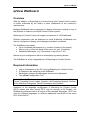
ipView Wallboard .............................................................. 5
Overview .......................................................................................... 5
Required Information ....................................................................... 5
Flowchart ......................................................................................... 6
Loading the Configuration Tool ........................................................ 7
Setting the IP Address ................................................................... 10
Dipswitch Settings............................................................................................10
Configuring Wallboards in Reporting for Contact Center ............... 15
Configuring Messages, Alarms and Schedules ............................. 21
Messages .........................................................................................................21
Alarms ..............................................................................................................24
Scheduled Messages ......................................................................................29
Avaya Documentation Links .......................................... 31
4
NN40011-026 Issue 1.2 BCM Rls 6.0
ipView WallBoard
ipView Wallboard
Overview
With the addition of Reporting for Contact Center the Contact Center system
is further enhanced by the facility to tailor Wallboards to the customer’s
requirements.
Multiple Wallboards can be assigned to display information relating to any of
the Skillsets or totals for the whole Contact Center system.
Reporting for Contact Center will support a maximum of 100 Wallboards.
Different parameters can be displayed on each Wallboard. Wallboards can
also be configured to display text messages and alarm conditions.
The WallBoard can display:
Up to 6 separate parameters (e.g. number of callers in the queue).
Alarms (e.g. a caller has been in the queue for over 10 minutes).
Scheduled Messages. (e.g. Remember to log off at 17:30).
Alarms may be configured to have an accompanying warning buzzer.
The WallBoard is a fully integrated part of Reporting for Contact Center.
Required Information
Log on information for the PC running Reporting for Contact Center.
IP address to be assigned to the Wallboard.
Parameters, Alarms and Messages that are to be displayed.
The ipView Configuration Tool.
Note: ipView SoftBoard can operate in UK English, North American English,
French, Canadian French, Italian, Spanish, Latin American Spanish, German,
Dutch, Brazilian Portuguese, Danish, Norwegian and Swedish.
Advances in the language configuration of Reporting for Contact Center
(RCC) means that even though RCC may be running in UK English, the
Wallboards connected can be a mixture of the available languages. RCC can
now use different languages on different wallboards connected to the same
RCC Web Host PC.
NN40011-026 Issue 1.2 BCM Rls 6.0
5
ipView WallBoard
Flowchart
This flowchart depicts the relevant steps required to install and configure an
IPView Wallboard.
Obtain an IP address for the WallBoard and load the configuration tool:
Refer to the Loading the Configuration Tool section of this guide.
Set the WallBoard switches to enable configuration: Refer to the
Dipswitch Settings section of this guide.
Connect the WallBoard to the network and power it up
Configure the WallBoard IP address using the configuration program:
Refer to the Setting the IP Address section of this guide.
Set the WallBoard switches back to normal operation: Refer to the
Dipswitch Settings section of this guide.
Configure WallBoard properties: Refer to the Configuring Wallboards in
Reporting for Contact Centre Configuration section of this guide.
Configure Messages, Alarms and Scheduled Messages: Refer to the
Configuring Alarms, Messages and Schedules section of this guide
6
NN40011-026 Issue 1.2 BCM Rls 6.0
ipView WallBoard
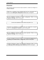
Loading the Configuration Tool
The IpView Wallboard will be supplied with a CD that contains the IPView
Configuration Tool for programming the wallboards IP address.
To Load the Configuration Tool on to a PC:
1. Insert the disk into the CD drive of the PC and open the drive to view
the files on the disk.
2. Double Click the SETUP icon.
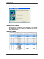
3. The Install Shield Wizard screen will appear.
NN40011-026 Issue 1.2 BCM Rls 6.0
7
ipView WallBoard
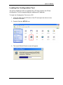
4. The Welcome to the ipView Config Installation screen will appear. Click
Next.
5. The Destination Directory screen will appear. Click Next.
8
NN40011-026 Issue 1.2 BCM Rls 6.0
ipView WallBoard
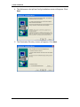
6. The Program folders screen will appear. Click Next.
7. The Current Settings screen will appear. Click Next.
NN40011-026 Issue 1.2 BCM Rls 6.0
9
ipView WallBoard
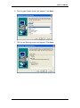
8. When the Configuration Tool has loaded click the Finish button.
Setting the IP Address
1. Before turning on the wallboard, set the dipswitches for the wallboard
as outlined in the chart on the back of the wallboard. This chart has
been replicated below :
Dipswitch Settings
10
NN40011-026 Issue 1.2 BCM Rls 6.0
ipView WallBoard
a) Set switch 8 to Off to enable IP use.
b) Set switch 7 to On to allow the eeprom to be updated.
c) Set switch 6 to On to set the IP address with the software
configuration tool.
2. Connect the wallboard to the PC with a cross over cable or to the
network via a hub / switch using a straight through cable.
3. Power up the wallboard.
4. The default communication IP address of the wallboard is briefly
displayed on the wallboard and is normally 192.168.3.200.
Note: You need to change the IP address of the PC to the same network
range as the wallboard. (Refer to the Networking Essentials Guide for
details of how to change IP addresses.
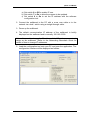
5. Load the configuration tool onto your PC and open the application. The
configuration interface will be displayed as follows:
NN40011-026 Issue 1.2 BCM Rls 6.0
11
ipView WallBoard
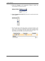
6. Within the IP configuration tool, check the Communication IP Address
of the wallboard is 192.168.3.200.
7. If it isn’t select File and Set up and change the IP address to
192.168.3.200.
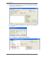
8. Select Commands, and Program sign IP Address.
12
NN40011-026 Issue 1.2 BCM Rls 6.0
ipView WallBoard
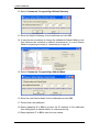
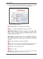
9. The Program Wallboard IP Address window will be displayed.
10. Enter the new wallboard IP address and click the OK button. You will
be notified that the programming is OK. (If you receive a message
saying that the Wallboard cannot be communicated to, check the
communication IP address and the IP address of the PC).
11. If a Gateway is required to enable remote connection to the wallboard
go to step 12, otherwise go to step 17.
NN40011-026 Issue 1.2 BCM Rls 6.0
13
ipView WallBoard
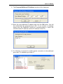
12. Select Commands, Program Sign Default Gateway.
13. Enter the Default Gateway for the wallboard and click OK.
14. It may also be necessary to change the wallboards Subnet Mask to one
that matches the customer’s network requirements. If a new Subnet
Mask is required go to step 14, otherwise go to step 16.
15. Select Commands, Program Sign Subnet Mask.
16. Enter the new Subnet Mask for the wallboard and click OK.
17. Power down the wallboard.
18. Reset dipswitch 6 to Off to prevent the IP address of the wallboard
from falling back to default when it is next powered up.
19. Reset dipswitch 7 to Off to save the new values.
14
NN40011-026 Issue 1.2 BCM Rls 6.0
ipView WallBoard
20. Connect the wallboard to the network and power up with the new
settings.
Configuring Wallboards in Reporting for Contact
Center
This part of the configuration is to be done on any PC that has access to the
Web Host PC or on the Web Host PC itself.
1. Access Reporting for Contact Center (refer to the Reporting for
Contact Center Guide for instructions on accessing RCC). You must
log into RCC with a username that has been configured to allow
configuration of wallboards (and also has Skillsets assigned to them).
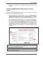
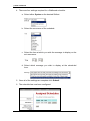
2. Select Contact Center Connection then the Select an IP Address
link: if there is more than one network card installed on the Web Host
PC, from the Select an IP Address drop down list select the IP
address (of Network Interface Card) that is to be used to communicate
with wallboards. Select the IP address that has been configured on the
Network Interface Card connected to the same network as the
wallboards.
Note: This is not the IP address of a wallboard itself. If you only have
one network card installed on the Web Host PC this setting will
default to the IP address of the card.
Note: To see the Contact Center Connection Screen you must be logged
in as an administrator of RCC.
NN40011-026 Issue 1.2 BCM Rls 6.0
15
ipView WallBoard
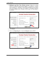
3. Wallboard and Real Time Refresh Interval. Select the refresh
interval for wallboard and real time displays. The default is 1 second
with an option for 3 seconds. This setting only applies to the refresh
rate of the display, not the data. For example if 3 seconds is selected
the display updates every 3 seconds, but the data is still calculated to
the second.
4. Click Submit.
5. Click on the Reporting link, to enter the Reports section of RCC.
16
NN40011-026 Issue 1.2 BCM Rls 6.0
ipView WallBoard
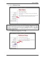
6. Click on Wallboard Setup.
Note: To be able to add and administer WallBoards the logged in user MUST
have Skillsets assigned. If current user has no Skillsets assigned then, logout
and log in with a username that has the appropriate rights. For further
information on creating users and assigning Skillsets refer to the Reporting
for Contact Center Guide.
7. Click Wallboard Assignment. Click Add.
NN40011-026 Issue 1.2 BCM Rls 6.0
17
ipView WallBoard
8. On the following screen the Wallboard will be configured. For this you
will need to know the IP Address of the hardware Wallboard.
9. Enter the following parameters:
IP / Network Name: The IP Address of the Wallboard.
Port : For a hardware wallboard this should be left at 3500.
Wallboard Skillset: The Skillset or System for the entire Contact
Center. For this example we will set it to System for port 3500. Skill1
would be chosen if we were configuring the Wallboard for Skill1 (the port
number would remain at 3500).
Language: The language that we wish our Wallboard to display in.
The language would make a difference on a Wallboard by altering the
letters in the abbreviations and the long view to display in the desired
language.
Type : Set to Hardware for a hardware Wallboard.
Title: Tick for a Title. Three of the displaying parameters will be lost if
a title is shown. A title will take the top line of text on the Wallboard.
Title Text : The title that will be shown.
Buzzer : For alerts.
Summary: Ticking the summary box will display the flowing
information in graphical format every hour, on the hour.
18
NN40011-026 Issue 1.2 BCM Rls 6.0
ipView WallBoard
Once the settings have been completed, click
Submit.
9. A list of assigned and configured wallboards is now available:
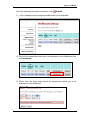
10. The edit the parameters that are to be displayed on the Wallboard click
on Parameters.
11. Select from the drop down boxes the parameters which are to be
displayed on the Wallboard.
NN40011-026 Issue 1.2 BCM Rls 6.0
19
ipView WallBoard
12. When a parameter is selected from a drop down box its concise
description in displayed in the lower text box.
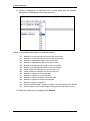
Below is a complete description of each parameter:
ID
IH
AD
AH
OD
OH
SH
SD
AO
AI
AA
AN
AL
QL
QT
Number of Incoming calls received in the current Day
Number of Incoming calls received in the current Hour
Number of Abandoned calls in the current Day
Number of Abandoned calls in the current Hour
Number of Outgoing calls made in the current Day
Number of Outgoing calls made in the current Hour
Grade of Service offered in the current Hour (%)
Grade of Service offered in the current Day (%)
Number of Agents on Outgoing calls
Number of Agents on Incoming calls
Number of Agents Available to receive calls
Number of Agents in the Not Ready state
Number of Agents Logged in
Current Queue Length - number of calls in the call queue for this Skillset
Current Queue Time for the longest waiting call for this Skillset (secs.)
13. When the choices are complete click Submit.
20
NN40011-026 Issue 1.2 BCM Rls 6.0
ipView WallBoard
Configuring Messages, Alarms and Schedules
Messages
Messages can be up to 64 characters in length.
The Real Time numerical value of any of the Parameters can be incorporated
into a Message by inserting the two-letter abbreviation for the Parameter into
the Message text.
The Parameter must be in capitals and in brackets, e.g. (AN) would insert the
current value of the Agent Not Ready parameter.
Example: “There are (AN) agents not ready”. If there are five agents not ready
when the Message is sent to the Wallboard, the format of the Message will be:
“There are 5 agents not ready”.
Messages will display on the ipView WallBoard for approximately 40
seconds.
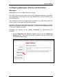
1. Access Reporting for Contact Center and go into the Wallboard
Setup section. You must log into the Contact Center as a user who
has Wallboard privileges.
NN40011-026 Issue 1.2 BCM Rls 6.0
21
ipView WallBoard
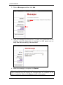
2. Click on Messages and then click Add.
3. Type your message into the text box. To make use of parameters in the
message enter the abbreviation in brackets i.e. (AN) agents are not
ready and calls are waiting to be answered!.
4. When the message is complete click Submit.
Note: It would generally be advised that messages are linked against an
alarm parameter that will display the message when the condition for the
alarm is satisfied. (Refer to the Alarms section of this guide.)
22
NN40011-026 Issue 1.2 BCM Rls 6.0
ipView WallBoard
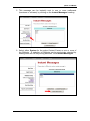
5. This message can be instantly sent to one or more wallboards
(hardware or software) by clicking on the Instant Messages heading.
6. Select either System for the entire Contact Center or one or more of
the Skillsets. A selection of Skillsets can be exclusively selected by
holding down the ctrl key during selection. Click Instant Messages.
NN40011-026 Issue 1.2 BCM Rls 6.0
23
ipView WallBoard
7. Select one of the existing messages or type a new message, then click
Send.
Alarms
Alarms can be configured to alert Agents to conditions within the Contact
Center.
e.g.
Less than 2 Agents are available to take calls.
An excessive amount of calls are in the queue.
Calls are waiting excessive times in the queue.
1000 calls have been answered during the day today.
A result of meeting these conditions is to display a message to alert the
agents on their individual desktops.
To Create an Alarm
(In this example a skillset alarm will be configured that will be displayed when
3 or less agents are available to take a call).
1. Follow steps 1 to 4 of the Messages subsection earlier in this section to
configure one or more messages relating to the parameters to which
you wish to alert the Agents.
24
NN40011-026 Issue 1.2 BCM Rls 6.0
ipView WallBoard
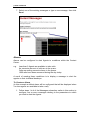
2. When the messages are complete click on the Alarms heading under
Wallboard Setup. Click Add.
3. Certain parameters now need to be set.
NN40011-026 Issue 1.2 BCM Rls 6.0
25
ipView WallBoard
a. Select the System or the appropriate Skillset to which the
alarms apply to and will be sent to.
b. Select the parameter name that you wish to monitor and set the
alarm against.
c. Set the start time of the day when you wish the alarm to be
used. Then select the comparison for the alarm and the alarm
threshold. If a message is to be utilized, the message to be
associated with this alarm should also be selected.
26
NN40011-026 Issue 1.2 BCM Rls 6.0
ipView WallBoard
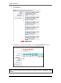
4. In this example three alarms have been configured. One to start at
08:30 to alarm for 5 or less Agents being Available. The seconds runs
from 12:00 to 17:59 for 6 or less agents being available. The third is
effective from 18:00 until 08:29 the following morning to monitor for 2 or
less Agents being available.
Note: If no time is selected (left at 00:00) then the alarm will apply 24 hours
per day.
NN40011-026 Issue 1.2 BCM Rls 6.0
27
ipView WallBoard
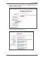
5. Click Submit.
6. The Alarms configured will display on the Assigned Alarms screen.
Note: That the Alarm above has been configured with 2 additional alarm
periods.
28
NN40011-026 Issue 1.2 BCM Rls 6.0
ipView WallBoard
Scheduled Messages
A Wallboard Schedule is a time and day(s) when a Wallboard Message is
automatically displayed on the Wallboard.
Examples would be to schedule a Message to display as a weekly reminder of
a fire alarm test, or to remind agents to log-in at the start of the working day.
To schedule a message
1. Follow steps 1 to 4 of the Messages subsection of this section.
2. Once the messages are configured they can be applied to a schedule.
From the Wallboard Setup Menu, click Schedules and then click Add.
3. The Add Schedule screen will be displayed.
NN40011-026 Issue 1.2 BCM Rls 6.0
29
ipView WallBoard
4. There are four settings required for a Wallboard schedule.
a. Select either System or the desired Skillset.
b. Select the recurrence of the schedule.
c. Select the time at which you wish the message to display on the
set recurrence.
d. Select which message you wish to display at the scheduled
time.
5. Once all of the settings are complete click Submit.
6. The schedule has now been configured.
30
NN40011-026 Issue 1.2 BCM Rls 6.0
ipView WallBoard
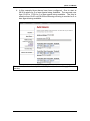
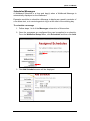
Avaya Documentation Links
Reporting for Contact Center Setup Set Up & Operations guide.
Reporting for Contact Center Troubleshooting and Maintenance guide
NN40011-026 Issue 1.2 BCM Rls 6.0
31
ipView WallBoard
32
NN40011-026 Issue 1.2 BCM Rls 6.0