1
BayRS Version 14.00
Part No. 308649-14.00 Rev 00
September 1999
4401 Great America Parkway
Santa Clara, CA 95054
Configuring X.25 Gateway
Services
Copyright © 1999 Nortel Networks
All rights reserved. Printed in the USA. September 1999.
The information in this document is subject to change without notice. The statements, configurations, technical data,
and recommendations in this document are believed to be accurate and reliable, but are presented without express or
implied warranty. Users must take full responsibility for their applications of any products specified in this document.
The information in this document is proprietary to Nortel Networks NA Inc.
The software described in this document is furnished under a license agreement and may only be used in accordance
with the terms of that license. A summary of the Software License is included in this document.
Trademarks
NORTEL NETWORKS is a trademark of Nortel Networks.
Bay Networks and FRE are registered trademarks and BayRS is a trademark of Nortel Networks.
All other trademarks and registered trademarks are the property of their respective owners.
Restricted Rights Legend
Use, duplication, or disclosure by the United States Government is subject to restrictions as set forth in subparagraph
(c)(1)(ii) of the Rights in Technical Data and Computer Software clause at DFARS 252.227-7013.
Notwithstanding any other license agreement that may pertain to, or accompany the delivery of, this computer
software, the rights of the United States Government regarding its use, reproduction, and disclosure are as set forth in
the Commercial Computer Software-Restricted Rights clause at FAR 52.227-19.
Statement of Conditions
In the interest of improving internal design, operational function, and/or reliability, Nortel Networks NA Inc. reserves
the right to make changes to the products described in this document without notice.
Nortel Networks NA Inc. does not assume any liability that may occur due to the use or application of the product(s)
or circuit layout(s) described herein.
Portions of the code in this software product may be Copyright © 1988, Regents of the University of California. All
rights reserved. Redistribution and use in source and binary forms of such portions are permitted, provided that the
above copyright notice and this paragraph are duplicated in all such forms and that any documentation, advertising
materials, and other materials related to such distribution and use acknowledge that such portions of the software were
developed by the University of California, Berkeley. The name of the University may not be used to endorse or
promote products derived from such portions of the software without specific prior written permission.
SUCH PORTIONS OF THE SOFTWARE ARE PROVIDED “AS IS” AND WITHOUT ANY EXPRESS OR
IMPLIED WARRANTIES, INCLUDING, WITHOUT LIMITATION, THE IMPLIED WARRANTIES OF
MERCHANTABILITY AND FITNESS FOR A PARTICULAR PURPOSE.
In addition, the program and information contained herein are licensed only pursuant to a license agreement that
contains restrictions on use and disclosure (that may incorporate by reference certain limitations and notices imposed
by third parties).
ii
308649-14.00 Rev 00
Nortel Networks NA Inc. Software License Agreement
NOTICE: Please carefully read this license agreement before copying or using the accompanying software or
installing the hardware unit with pre-enabled software (each of which is referred to as “Software” in this Agreement).
BY COPYING OR USING THE SOFTWARE, YOU ACCEPT ALL OF THE TERMS AND CONDITIONS OF
THIS LICENSE AGREEMENT. THE TERMS EXPRESSED IN THIS AGREEMENT ARE THE ONLY TERMS
UNDER WHICH NORTEL NETWORKS WILL PERMIT YOU TO USE THE SOFTWARE. If you do not accept
these terms and conditions, return the product, unused and in the original shipping container, within 30 days of
purchase to obtain a credit for the full purchase price.
1. License Grant. Nortel Networks NA Inc. (“Nortel Networks”) grants the end user of the Software (“Licensee”) a
personal, nonexclusive, nontransferable license: a) to use the Software either on a single computer or, if applicable, on
a single authorized device identified by host ID, for which it was originally acquired; b) to copy the Software solely
for backup purposes in support of authorized use of the Software; and c) to use and copy the associated user manual
solely in support of authorized use of the Software by Licensee. This license applies to the Software only and does not
extend to Nortel Networks Agent software or other Nortel Networks software products. Nortel Networks Agent
software or other Nortel Networks software products are licensed for use under the terms of the applicable Nortel
Networks NA Inc. Software License Agreement that accompanies such software and upon payment by the end user of
the applicable license fees for such software.
2. Restrictions on use; reservation of rights. The Software and user manuals are protected under copyright laws.
Nortel Networks and/or its licensors retain all title and ownership in both the Software and user manuals, including
any revisions made by Nortel Networks or its licensors. The copyright notice must be reproduced and included with
any copy of any portion of the Software or user manuals. Licensee may not modify, translate, decompile, disassemble,
use for any competitive analysis, reverse engineer, distribute, or create derivative works from the Software or user
manuals or any copy, in whole or in part. Except as expressly provided in this Agreement, Licensee may not copy or
transfer the Software or user manuals, in whole or in part. The Software and user manuals embody Nortel Networks’
and its licensors’ confidential and proprietary intellectual property. Licensee shall not sublicense, assign, or otherwise
disclose to any third party the Software, or any information about the operation, design, performance, or
implementation of the Software and user manuals that is confidential to Nortel Networks and its licensors; however,
Licensee may grant permission to its consultants, subcontractors, and agents to use the Software at Licensee’s facility,
provided they have agreed to use the Software only in accordance with the terms of this license.
3. Limited warranty. Nortel Networks warrants each item of Software, as delivered by Nortel Networks and properly
installed and operated on Nortel Networks hardware or other equipment it is originally licensed for, to function
substantially as described in its accompanying user manual during its warranty period, which begins on the date
Software is first shipped to Licensee. If any item of Software fails to so function during its warranty period, as the sole
remedy Nortel Networks will at its discretion provide a suitable fix, patch, or workaround for the problem that may be
included in a future Software release. Nortel Networks further warrants to Licensee that the media on which the
Software is provided will be free from defects in materials and workmanship under normal use for a period of 90 days
from the date Software is first shipped to Licensee. Nortel Networks will replace defective media at no charge if it is
returned to Nortel Networks during the warranty period along with proof of the date of shipment. This warranty does
not apply if the media has been damaged as a result of accident, misuse, or abuse. The Licensee assumes all
responsibility for selection of the Software to achieve Licensee’s intended results and for the installation, use, and
results obtained from the Software. Nortel Networks does not warrant a) that the functions contained in the software
will meet the Licensee’s requirements, b) that the Software will operate in the hardware or software combinations that
the Licensee may select, c) that the operation of the Software will be uninterrupted or error free, or d) that all defects
in the operation of the Software will be corrected. Nortel Networks is not obligated to remedy any Software defect that
cannot be reproduced with the latest Software release. These warranties do not apply to the Software if it has been (i)
altered, except by Nortel Networks or in accordance with its instructions; (ii) used in conjunction with another
vendor’s product, resulting in the defect; or (iii) damaged by improper environment, abuse, misuse, accident, or
negligence. THE FOREGOING WARRANTIES AND LIMITATIONS ARE EXCLUSIVE REMEDIES AND ARE
IN LIEU OF ALL OTHER WARRANTIES EXPRESS OR IMPLIED, INCLUDING WITHOUT LIMITATION ANY
WARRANTY OF MERCHANTABILITY OR FITNESS FOR A PARTICULAR PURPOSE. Licensee is responsible
308649-14.00 Rev 00
iii
for the security of its own data and information and for maintaining adequate procedures apart from the Software to
reconstruct lost or altered files, data, or programs.
4. Limitation of liability. IN NO EVENT WILL NORTEL NETWORKS OR ITS LICENSORS BE LIABLE FOR
ANY COST OF SUBSTITUTE PROCUREMENT; SPECIAL, INDIRECT, INCIDENTAL, OR CONSEQUENTIAL
DAMAGES; OR ANY DAMAGES RESULTING FROM INACCURATE OR LOST DATA OR LOSS OF USE OR
PROFITS ARISING OUT OF OR IN CONNECTION WITH THE PERFORMANCE OF THE SOFTWARE, EVEN
IF NORTEL NETWORKS HAS BEEN ADVISED OF THE POSSIBILITY OF SUCH DAMAGES. IN NO EVENT
SHALL THE LIABILITY OF NORTEL NETWORKS RELATING TO THE SOFTWARE OR THIS AGREEMENT
EXCEED THE PRICE PAID TO NORTEL NETWORKS FOR THE SOFTWARE LICENSE.
5. Government Licensees. This provision applies to all Software and documentation acquired directly or indirectly by
or on behalf of the United States Government. The Software and documentation are commercial products, licensed on
the open market at market prices, and were developed entirely at private expense and without the use of any U.S.
Government funds. The license to the U.S. Government is granted only with restricted rights, and use, duplication, or
disclosure by the U.S. Government is subject to the restrictions set forth in subparagraph (c)(1) of the Commercial
Computer Software––Restricted Rights clause of FAR 52.227-19 and the limitations set out in this license for civilian
agencies, and subparagraph (c)(1)(ii) of the Rights in Technical Data and Computer Software clause of DFARS
252.227-7013, for agencies of the Department of Defense or their successors, whichever is applicable.
6. Use of Software in the European Community. This provision applies to all Software acquired for use within the
European Community. If Licensee uses the Software within a country in the European Community, the Software
Directive enacted by the Council of European Communities Directive dated 14 May, 1991, will apply to the
examination of the Software to facilitate interoperability. Licensee agrees to notify Nortel Networks of any such
intended examination of the Software and may procure support and assistance from Nortel Networks.
7. Term and termination. This license is effective until terminated; however, all of the restrictions with respect to
Nortel Networks’ copyright in the Software and user manuals will cease being effective at the date of expiration of the
Nortel Networks copyright; those restrictions relating to use and disclosure of Nortel Networks’ confidential
information shall continue in effect. Licensee may terminate this license at any time. The license will automatically
terminate if Licensee fails to comply with any of the terms and conditions of the license. Upon termination for any
reason, Licensee will immediately destroy or return to Nortel Networks the Software, user manuals, and all copies.
Nortel Networks is not liable to Licensee for damages in any form solely by reason of the termination of this license.
8. Export and Re-export. Licensee agrees not to export, directly or indirectly, the Software or related technical data
or information without first obtaining any required export licenses or other governmental approvals. Without limiting
the foregoing, Licensee, on behalf of itself and its subsidiaries and affiliates, agrees that it will not, without first
obtaining all export licenses and approvals required by the U.S. Government: (i) export, re-export, transfer, or divert
any such Software or technical data, or any direct product thereof, to any country to which such exports or re-exports
are restricted or embargoed under United States export control laws and regulations, or to any national or resident of
such restricted or embargoed countries; or (ii) provide the Software or related technical data or information to any
military end user or for any military end use, including the design, development, or production of any chemical,
nuclear, or biological weapons.
9. General. If any provision of this Agreement is held to be invalid or unenforceable by a court of competent
jurisdiction, the remainder of the provisions of this Agreement shall remain in full force and effect. This Agreement
will be governed by the laws of the state of California.
Should you have any questions concerning this Agreement, contact Nortel Networks, 4401 Great America Parkway,
P.O. Box 58185, Santa Clara, California 95054-8185.
LICENSEE ACKNOWLEDGES THAT LICENSEE HAS READ THIS AGREEMENT, UNDERSTANDS IT, AND
AGREES TO BE BOUND BY ITS TERMS AND CONDITIONS. LICENSEE FURTHER AGREES THAT THIS
AGREEMENT IS THE ENTIRE AND EXCLUSIVE AGREEMENT BETWEEN NORTEL NETWORKS AND
LICENSEE, WHICH SUPERSEDES ALL PRIOR ORAL AND WRITTEN AGREEMENTS AND
COMMUNICATIONS BETWEEN THE PARTIES PERTAINING TO THE SUBJECT MATTER OF THIS
AGREEMENT. NO DIFFERENT OR ADDITIONAL TERMS WILL BE ENFORCEABLE AGAINST NORTEL
NETWORKS UNLESS NORTEL NETWORKS GIVES ITS EXPRESS WRITTEN CONSENT, INCLUDING AN
EXPRESS WAIVER OF THE TERMS OF THIS AGREEMENT.
iv
308649-14.00 Rev 00
Contents
Preface
Before You Begin .............................................................................................................. ix
Text Conventions ............................................................................................................... x
Acronyms .......................................................................................................................... xi
Hard-Copy Technical Manuals ..........................................................................................xii
How to Get Help ...............................................................................................................xii
Chapter 1
X.25 Gateway Overview
X.25 Gateway Topology ..................................................................................................1-2
Network Interfaces ..........................................................................................................1-3
X.25 Level 3 (PLP) Interface ....................................................................................1-3
X.25 Level 2 (LAPB-Only) Interface .........................................................................1-3
TCP Interface ...........................................................................................................1-4
What X.25 Gateway Does ..............................................................................................1-4
Protocol Translation ..................................................................................................1-4
Establishing Connections from the X.25 Equipment ................................................1-6
SVCs with a Called X.121 Address ...................................................................1-6
SVCs Without a Called X.121 Address .............................................................1-7
Permanent Virtual Circuits (PVCs) ....................................................................1-7
Establishing Connections from the X.25 Level 2 (LAPB) Terminal ...........................1-8
Establishing Connections During Failure Conditions for
PVC/TCP Translation ...............................................................................................1-8
Reestablishing the X.25 Connection ..................................................................1-8
Reestablishing the TCP/IP Connection .............................................................1-9
Establishing Connections from the TCP/IP Host ......................................................1-9
Connection Summary ...................................................................................................1-11
308649-14.00 Rev 00
v
Handling Large Data Messages ...................................................................................1-12
How X.25 Handles Large Data Messages .............................................................1-12
How TCP Handles Large Data Messages .............................................................1-12
X.25 Gateway Message Block Options ..................................................................1-13
Chapter 2
Enabling X.25 Gateway
Preparing a Configuration File ........................................................................................2-1
Configuring X.25 IPEX Services .....................................................................................2-1
Enabling X.25 Gateway Services ...................................................................................2-2
Adding an Entry to the IPEX Mapping Table ............................................................2-2
Configuring Mapping Parameters ............................................................................2-7
IPEX Mapping Parameters Windows .......................................................................2-7
Parameters for PVC and SVC Connections .............................................................2-9
Parameters for TCP Connections ..........................................................................2-11
Replicating a Configuration ..........................................................................................2-12
Parameters for Replicating Connections ......................................................................2-18
Index
vi
308649-14.00 Rev 00
Figures
Figure 1-1.
Sample Network Topology Using X.25 Gateway ......................................1-2
Figure 1-2.
How X.25 Gateway Establishes a Session (X.25 Initiated) ......................1-5
Figure 1-3.
Reestablishing X.25 Connections ............................................................1-9
Figure 1-4.
Reestablishing TCP/IP Connections ........................................................1-9
Figure 1-5.
How X.25 Gateway Establishes a Session (TCP Initiated) ....................1-10
Figure 1-6.
Role of the X.25 and TCP Protocol Stacks in X.25 Gateway .................1-11
Figure 2-1.
IPEX Mapping Add Window for Source PVC ...........................................2-4
Figure 2-2.
IPEX Mapping Parameters Window for PVC ...........................................2-8
Figure 2-3.
IPEX Mapping Parameters Window for SVC ...........................................2-8
Figure 2-4.
IPEX Mapping Parameters Window for TCP ............................................2-9
Figure 2-5.
IPEX Mapping Table Configuration Window ..........................................2-13
Figure 2-6.
IPEX Mapping Replication Window .......................................................2-15
Figure 2-7.
IPEX Mapping Table Configuration Window After
Replicating a PVC-to-TCP Connection ..................................................2-16
Figure 2-8.
IPEX Mapping Table Configuration Window After
Replicating a TCP-to-PVC Connection ..................................................2-17
308649-14.00 Rev 00
vii
Preface
This guide describes X.25 Gateway services and what you do to start and
customize X.25 Gateway services on a Nortel Networks™ router.
Before You Begin
Before using this guide, you must complete the following procedures. For a new
router:
•
Install the router (refer to the installation manual that came with your router).
•
Connect the router to the network and create a pilot configuration file (refer to
Quick-Starting Routers, Configuring BayStack Remote Access, or Connecting
ASN Routers to a Network).
Make sure that you are running the latest version of Nortel Networks BayRS™ and
Site Manager software. For information about upgrading BayRS and Site
Manager, see the upgrading guide for your version of BayRS.
308649-14.00 Rev 00
ix
Configuring X.25 Gateway Services
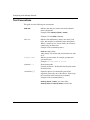
Text Conventions
This guide uses the following text conventions:
bold text
Indicates text that you need to enter and command
names and options.
Example: Enter show ip {alerts | routes}
Example: Use the dinfo command.
italic text
Indicates file and directory names, new terms, book
titles, and variables in command syntax descriptions.
Where a variable is two or more words, the words are
connected by an underscore.
Example: If the command syntax is:
show at <valid_route>
valid_route is one variable and you substitute one value
for it.
screen text
Indicates system output, for example, prompts and
system messages.
Example: Set Trap Monitor Filters
separator ( > )
Shows menu paths.
Example: Protocols > IP identifies the IP option on the
Protocols menu.
vertical line ( | )
Separates choices for command keywords and
arguments. Enter only one of the choices. Do not type
the vertical line when entering the command.
Example: If the command syntax is:
show ip {alerts | routes}, you enter either:
show ip alerts or show ip routes, but not both.
x
308649-14.00 Rev 00
Preface
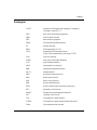
Acronyms
CCITT
International Telegraph and Telephone Consultative
Committee (now ITU-T)
DCE
data circuit-terminating equipment
DDN
Defense Data Network
DTE
data terminal equipment
FDDI
Fiber Distributed Data Interface
IP
Internet Protocol
IPEX
IP Encapsulation of X.25
ITU-T
International Telecommunications
Union–Telecommunications (formerly CCITT)
LAN
local area network
LAPB
Link Access Procedure Balanced
LCN
logical channel number
MAN
metropolitan area network
MIB
Management Information Base
MCT1
Multichannel T1
MTU
maximum transmission unit
PDN
Public Data Network
PLP
Packet Layer Protocol
PPP
Point-to-Point Protocol
PToP
Point-to-Point (Nortel Networks proprietary)
PVC
permanent virtual circuit
SNMP
Simple Network Management Protocol
SVC
switched virtual circuit
TCP
Transmission Control Protocol
TCP/IP
Transmission Control Protocol/Internet Protocol
Telnet
Telecommunication Network
308649-14.00 Rev 00
xi
Configuring X.25 Gateway Services
TFTP
Trivial File Transfer Protocol
WAN
wide area network
Hard-Copy Technical Manuals
You can print selected technical manuals and release notes free, directly from the
Internet. Go to support.baynetworks.com/library/tpubs/. Find the product for
which you need documentation. Then locate the specific category and model or
version for your hardware or software product. Using Adobe Acrobat Reader, you
can open the manuals and release notes, search for the sections you need, and print
them on most standard printers. You can download Acrobat Reader free from the
Adobe Systems Web site, www.adobe.com.
You can purchase selected documentation sets, CDs, and technical publications
through the collateral catalog. The catalog is located on the World Wide Web at
support.baynetworks.com/catalog.html and is divided into sections arranged
alphabetically:
•
The “CD ROMs” section lists available CDs.
•
The “Guides/Books” section lists books on technical topics.
•
The “Technical Manuals” section lists available printed documentation sets.
How to Get Help
If you purchased a service contract for your Nortel Networks product from a
distributor or authorized reseller, contact the technical support staff for that
distributor or reseller for assistance.
If you purchased a Nortel Networks service program, contact one of the following
Nortel Networks Technical Solutions Centers:
xii
Technical Solutions Center
Telephone Number
Billerica, MA
800-2LANWAN (800-252-6926)
Santa Clara, CA
800-2LANWAN (800-252-6926)
Valbonne, France
33-4-92-96-69-68
Sydney, Australia
61-2-9927-8800
Tokyo, Japan
81-3-5402-7041
308649-14.00 Rev 00
Chapter 1
X.25 Gateway Overview
X.25 Gateway lets you send and receive messages between X.25 and
Transmission Control Protocol/Internet Protocol (TCP/IP) networks. It maps TCP
sockets to X.25 virtual circuits (and vice versa) or to Link Access Procedure
Balanced (LAPB) point-to-point connection identifiers.
The Gateway software supports X.25 permanent virtual circuits (PVCs) and
switched virtual circuits (SVCs), as well as TCP/IP over all interface types
supported in the Nortel Networks router.
X.25 Gateway supports:
•
TCP/IP over Fiber Distributed Data Interface (FDDI), Ethernet, and token
ring LAN media, or over X.25, frame relay, Asynchronous Transfer Mode
(ATM), and switched multimegabit data service (SMDS), wide area network
(WAN), or metropolitan area network (MAN) media
•
X.25 Levels 2 and 3 over synchronous interfaces (6 MB/s and below) or
Multichannel T1 (MCT1) interfaces
•
10 VCs per logical channel for the FRE2-040-32MB platform, for a total of
240 VCs per slot
•
32 VCs per channel for the FRE1-060-64MB, for a total of 310 VCs per slot
Use Site Manager’s Configuration Manager to configure a system for X.25
Gateway services.
308649-14.00 Rev 00
1-1
Configuring X.25 Gateway Services
X.25 Gateway Topology
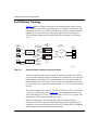
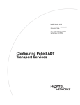
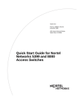
Figure 1-1 shows a topology consisting of two Nortel Networks router systems
and a TCP/IP network. The top system serves as a TCP/IP-to-X.25 gateway. The
bottom system serves as a TCP/IP-to-LAPB gateway. In this example, terminals
connected to X.25 networks can exchange messages with host systems on a
TCP/IP network through the Nortel Networks routers using the X.25 Gateway
service.
X.25
terminals
X.25 Level 3
connections
X.25
concentrator
X.25
gateway
router
V.35 or
T1 links
TCP
connections
TCP/IP
V.35 or
T1 links
LAPB
concentrator
Physical
(V.35) links
X.25 Level
(LAPB)
connections
TCP/IP
host
X.25
gateway
router
TCP/IP
host
X250022A
Figure 1-1.
Sample Network Topology Using X.25 Gateway
The router translates data received from X.25 virtual connections into TCP data
packets and forwards those packets out through TCP connections. The router also
translates data received from TCP connections into X.25 data and forwards the
data out through X.25 connections. You can connect the equipment to the router
by a leased line, an X.25 packet-switched network, or a T1 or E1 circuit-switched
network.
You can also configure the router as a TCP/IP-to-CCITT (now ITU-T) X.25 Level
2 gateway as in the bottom part of Figure 1-1. This configuration allows access
from LAPB-based (X.25 Level 2) equipment with no X.25 Level 3 support. This
manual refers to this feature as LAPB-only support.
With this configuration, the router translates data received from LAPB
connections to TCP data packets and forwards those packets out through TCP
connections. It also translates data received from TCP connections to LAPB data
and forwards the data out through LAPB connections.
1-2
308649-14.00 Rev 00
X.25 Gateway Overview
Network Interfaces
Nortel Networks routers that support X.25 Gateway services use the following
protocols:
•
X.25 Level 3 Packet Layer Protocol (PLP)
•
X.25 Level 2 Protocol (LAPB)
•
Transmission Control Protocol (TCP)
X.25 Level 3 (PLP) Interface
On an X.25 Level 3 interface, you can create and configure multiple virtual
circuits, including:
•
Permanent virtual circuits
•
Switched virtual circuits, with or without called X.121 addresses
You can create a set of either of these connections or a combination of the two. On
any X.25 interface, you can configure either X.25 Gateway service or other types
of X.25 services, such as Public Data Network (PDN), Point-to-Point (PtoP), and
Defense Data Network (DDN). If you configure X.25 Gateway service on an X.25
interface, the software translates data sent and received between the X.25 network
interface and the TCP/IP network interface. It uses X.25 flow control mechanisms
to detect congestion in the X.25 connection.
X.25 Gateway uses the X.25 Level 3 client interface to:
•
Open and close X.25 connections
•
Send data to the X.25 module for transmission
•
Process received data delivered from the X.25 module
•
Control the flow of data across the client interface
X.25 Level 2 (LAPB-Only) Interface
X.25 Gateway also supports a direct LAPB interface, so terminals can transfer
data in LAPB format without using the X.25 packet layer. You can select specific
LAPB link circuits for the translation service to use instead of the X.25 PLP.
308649-14.00 Rev 00
1-3
Configuring X.25 Gateway Services
TCP Interface
X.25 Gateway appears to TCP as a client. As such, the software specifies one
socket for the local TCP interface (consisting of its IP address and TCP port
number) and another socket for the remote TCP interface to establish a
connection. Each X.25 connection corresponds to only one TCP connection.
Since many TCP connections may be active concurrently to support many
Gateway sessions, a large range of TCP port numbers creates separate sockets for
individual sessions. The port numbers reserved for X.25 Gateway service are
12,304 to 16,399.
X.25 Gateway uses the TCP client interface to
•
Open, close, and check the status of TCP connections.
•
Send data to the TCP module for transmission.
•
Process received data delivered from the TCP module.
•
Control the flow of data across the client interface.
What X.25 Gateway Does
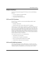
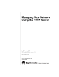
X.25 Gateway consists of a source circuit and a destination circuit. The gateway
receives the first incoming connection on the source circuit, and attempts to
establish an outgoing connection on the destination circuit. In Figure 1-2, the
source circuit is the one with the X.25 connection.
Protocol Translation
Figure 1-2 shows the sequence of establishing the translation session when the
connection request comes from the X.25 terminal.
1-4
308649-14.00 Rev 00
X.25 Gateway Overview
X.25
gateway
router
X.25
terminal
TCP/IP
host
Step 1
X.25
connection
requested
X.25
terminal
X.25
gateway
router
TCP/IP
host
Step 2
X.25
request
pending
X.25
terminal
X.25
gateway
router
TCP
connection
attempt
TCP/IP
host
Step 3
X.25
request
pending
X.25
terminal
X.25
gateway
router
TCP
connection
accepted
TCP/IP
host
Step 4
X.25
request
accepted
TCP
connection
established
X250023A
Figure 1-2.
How X.25 Gateway Establishes a Session (X.25 Initiated)
If the router detects congestion on the receiving side of the network, it controls the
data flow by queuing the requests on the sending side until the congestion lifts or
the connection terminates.
308649-14.00 Rev 00
1-5
Configuring X.25 Gateway Services
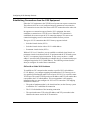
Establishing Connections from the X.25 Equipment
Either the X.25 equipment or the TCP/IP-based system can request a connection.
The software relies on a set of configured mapping parameters to associate the
X.25 connection on one side of the router to the TCP connection on the other side.
In response to a connection request from the X.25 equipment, the router
establishes a connection to a TCP/IP server. When this TCP connection is
established, the router accepts the X.25 connection attempt. This one-to-one
connection mapping creates a consistent and reliable Gateway session.
The types of X.25 connections that X.25 Gateway supports include:
•
Switched virtual circuits (SVCs)
•
Switched virtual circuits with no X.121 called address
•
Permanent virtual circuits (PVCs)
With an X.25 Level 3 interface, you can establish a switched virtual circuit or a
permanent virtual circuit between the X.25 equipment and the TCP-based system.
An SVC is a temporary logical connection. It may or may not have a “called
address” associated with it (depending on whether the type of connection that you
configured required an X.121 called address). The following sections describe
what you configure for each of these connections.
SVCs with a Called X.121 Address
To establish an SVC connection that contains a specified X.25 called address
(X.121 address), you configure mapping information that X.25 Gateway uses to
set a path for forwarding data traffic received on an X.25 SVC to a specific remote
TCP/IP peer. The remote TCP/IP peer has an IP address and TCP port number that
correspond to the X.25 called address. This correspondence is the mapping
information that you must configure for X.25-to-TCP conversion. The mapping
information consists of:
1-6
•
The point of attachment (that is, the circuit interface) on the Gateway system
at which the SVC establishes the connection
•
The X.25 called address of the incoming connection
•
The associated remote TCP socket (IP address and TCP port number) that
identifies the remote end of the TCP connection
308649-14.00 Rev 00
X.25 Gateway Overview
SVCs Without a Called X.121 Address
When the X.25 SVC connection does not contain an X.121 called address in the
incoming call request packet, you specify the SVC service on that circuit to be a
“special” SVC service interface by configuring:
•
The circuit interface in X.25 Gateway at which the SVC establishes the
connection
•
The SVC service interface on that circuit, which is “special” in that it must be
set up as a data terminal equipment (DTE) interface, instead of as a data
circuit-terminating equipment (DCE) interface
•
The associated remote TCP socket (remote IP address and TCP port number)
that identifies the remote end of the TCP connection
The router uses this information to form a translation session by accepting this
connection and establishing an associated TCP connection.
Permanent Virtual Circuits (PVCs)
For each permanent virtual circuit connection between the X.25 system and X.25
Gateway, there is a corresponding TCP connection set up between X.25 Gateway
and the TCP/IP peer. This connection remains established until either:
•
The X.25 equipment resets the PVC connection.
•
The X.25 interface is restarted.
•
The TCP peer terminates the TCP connection.
The mapping information that you must configure is:
•
The circuit interface for the PVC connection
•
The logical channel number (LCN) of the PVC connection
•
The associated remote TCP socket (IP address and TCP port number) that
identifies the remote end of the TCP connection
308649-14.00 Rev 00
1-7
Configuring X.25 Gateway Services
Establishing Connections from the X.25 Level 2 (LAPB) Terminal
The router uses a similar procedure for establishing LAPB-to-TCP connections.
You must specify the mapping information needed to configure the connection,
specifically:
•
The circuit interface through which X.25 Gateway will establish a LAPB
connection
•
Its associated remote TCP socket, which identifies the remote end of the TCP
connection
This mapping information sets up the path for forwarding data traffic received in a
LAPB circuit to a specific remote TCP/IP server and for forwarding data traffic
received from a TCP connection to a specific LAPB circuit.
When it has established this LAPB-to-TCP translation session, X.25 Gateway
translates the LAPB information frames it receives from the LAPB terminals into
TCP data segments, and vice versa.
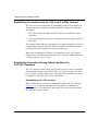
Establishing Connections During Failure Conditions for
PVC/TCP Translation
The X.25 Gateway software running on X.25 PVC devices is able to reestablish a
connection when a fault occurs at the TCP/IP or X.25 physical layer. You do not
have to enable or configure this feature. The figures below show how the software
reestablishes a connection between X.25 and TCP/IP.
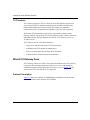
Reestablishing the X.25 Connection
When a physical layer fault occurs (a disconnected cable) at the X.25 interface
(Figure 1-3), X.25 Gateway disconnects the associated TCP connections. It
reestablishes the TCP connections to the mapped X.25 virtual circuits when the
X.25 interface is again available.
1-8
308649-14.00 Rev 00
X.25 Gateway Overview
X.25
gateway
router
TCP/IP
host
TCP
connections
reset
X.25
terminal
X.25
interface
down
X250024A
Figure 1-3.
Reestablishing X.25 Connections
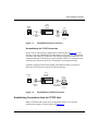
Reestablishing the TCP/IP Connection
In the event of a physical layer fault on the TCP/IP interface (Figure 1-4), X.25
Gateway resets any established TCP connections as well as the X.25 connections
associated with each TCP connection. The software attempts to reestablish a TCP
connection until the TCP interface is again available. When TCP connections are
available, the software resets the X.25 connections to an operational state.
Examples of physical layer faults include a disconnected cable or a failure at
either the X.25 Gateway or remote TCP/IP host interface.
X.25
gateway
router
TCP/IP
host
X.25
interface
down
X.25
terminal
TCP
connections
reestablished
X250025A
Figure 1-4.
Reestablishing TCP/IP Connections
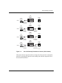
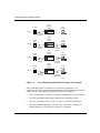
Establishing Connections from the TCP/IP Host
When a TCP/IP-based system issues a connection request, X.25 Gateway
performs the sequence of actions shown in Figure 1-5.
308649-14.00 Rev 00
1-9
Configuring X.25 Gateway Services
X.25
gateway
router
TCP/IP
host
X.25
terminal
Step 1
Connection
requested
X.25
gateway
router
TCP/IP
host
X.25
terminal
Step 2
Request
pending
X.25
gateway
router
TCP/IP
host
X.25
connection
attempt
X.25
terminal
Step 3
Request
pending
X.25
gateway
router
TCP/IP
host
X.25
connection
accepted
X.25
terminal
Step 4
Request
accepted
X.25
connection
established
X250026A
Figure 1-5.
How X.25 Gateway Establishes a Session (TCP Initiated)
After establishing the X.25 connection, X.25 Gateway accepts the TCP
connection. This one-to-one connection mapping provides another consistent and
reliable session. The mapping information you need to configure is:
1-10
•
The circuit interface on which X.25 Gateway establishes the TCP connection
•
The TCP port number that uniquely identifies the translation session
•
The type of connection, SVC or PVC, at the X.25 end of the connection
•
The logical channel number (LCN) of the PVC connection, or the pair of
calling and called X.121 addresses of the SVC connection
308649-14.00 Rev 00
X.25 Gateway Overview
After establishing this X.25-to-TCP session, X.25 Gateway translates X.25 Level
3 data packets received from the X.25 client terminals to TCP data segments, and
vice versa.
Connection Summary
To set up a reliable X.25 Gateway session, both sides must successfully establish
the connections. When one side receives a connection indication, the other side
initiates a connection attempt. If the connection attempt fails on the far side, the
near side rejects the connection request it received.
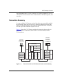
Figure 1-6 shows how X.25 Gateway mediates the interaction between the two
protocol stacks as the data flows between the X.25 client terminals and the
TCP-based hosts.
Information
from/to other
TCP hosts
or other Gateway
routers
Information
from/to other
X.25 terminals
X.25 level 2
TCP
IP
IEEE 802.3
FDDI
MCT1/E1
V.35
SYNC
X.25 level 3
X.25 level 2
SNMP
IEEE 802.2
IEEE 802.5
SNMP
X.25 level 3
X.25 Gateway
TCP
IP
SNMP
IEEE 802.2
IEEE 802.3
X250013B
Figure 1-6.
308649-14.00 Rev 00
Role of the X.25 and TCP Protocol Stacks in X.25 Gateway
1-11
Configuring X.25 Gateway Services
The TCP and X.25 communication stacks share the responsibility for maintaining
reliable and efficient data flow. If data loss occurs on one side, that side
retransmits the lost data. In addition, both sides independently maintain protocol
flow control.
Data loss may result from either software or hardware errors, or catastrophic
failures. Redundancy in network design is critical for handling these types of data
communication failures.
Handling Large Data Messages
X.25 is a message-based protocol, and TCP is an unstructured stream protocol.
They differ in the way they send outgoing traffic and deliver incoming traffic to
their clients.
How X.25 Handles Large Data Messages
When the X.25 client submits an X.25 message that is larger than an X.25 packet
size, the X.25 protocol fragments the message. X.25 then transmits the sequence
of packets containing these fragments. Within each packet, X.25 includes a flag
that indicates the fragmentation and aids in the reassembly process at the
receiving end.
How TCP Handles Large Data Messages
TCP, on the other hand, does not have a flag to mark fragmentation of messages
that are larger than the TCP maximum transmission unit (MTU) size. The portion
that does not fit into one TCP data segment is sent in a subsequent data segment.
Without the flag and any indication of the size of the message, the TCP client has
no way of determining the boundary of a message; that is, whether the complete
message is contained within one or in several data segments. When X.25 Gateway
receives the X.25 user data and translates it to a TCP data segment, the message
boundary is lost.
To minimize changes in the existing host applications, X.25 Gateway maintains
the X.25 message boundary. It structures the application information into message
blocks before encapsulating it in TCP data segments. Each message block
contains a header and a data portion.
1-12
308649-14.00 Rev 00
X.25 Gateway Overview
X.25 Gateway Message Block Options
You can configure X.25 Gateway with the following message block options.
•
No message block structure in any TCP segment -- X.25 Gateway translates
each TCP data segment as a complete message.
•
Message length specified -- The header portion of the message contains a
2-byte message length field. The data portion holds the actual application
information. The length field indicates the total length of the application data
portion in the message block.
•
Message version, type, and length specified in the header -- The header
specifies the version of the message header format, including a More flag bit.
The Type field specifies the message type, DATA. The data portion holds the
actual application information.
The message block options that let you specify the message length allow TCP
clients to determine message boundaries. Depending on the size of the message
block, a TCP data segment can contain multiple message blocks. A larger
message block may be transmitted in several TCP data segments. With the 2-byte
length field, the maximum length of a message block that X.25 Gateway can send
and receive using TCP is 64 KB.
Note: While the maximum length of the X.25 message that X.25 Gateway can
send to the terminal is 64 KB, the maximum length of the X.25 message that
X.25 Gateway can receive from the terminal is 4 KB.
308649-14.00 Rev 00
1-13
Chapter 2
Enabling X.25 Gateway
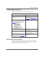
This chapter, as outlined in the following table, describes how to use the
Configuration Manager to set up X.25 Gateway services.
Section
Page
Preparing a Configuration File
2-1
Configuring X.25 IPEX Services
2-1
Enabling X.25 Gateway Services
2-2
Replicating a Configuration
2-12
Preparing a Configuration File
Before you configure X.25 Gateway:
1.
Create and save a configuration file that has at least one WAN interface.
2.
Retrieve the configuration file in local, remote, or dynamic mode.
3.
Specify router hardware if this is a local-mode configuration file.
Refer to Configuring and Managing Routers with Site Manager for instructions.
Configuring X.25 IPEX Services
When you enable X.25 Gateway services, you must configure X.25 IPEX
services. Refer to Chapters 3 and 4 of Configuring X.25 Services for instructions
on enabling X.25 and editing X.25 parameters. Refer to Chapter 5 of that guide
for instructions on configuring IPEX.
308649-14.00 Rev 00
2-1
Configuring X.25 Gateway Services
Enabling X.25 Gateway Services
To enable X.25 Gateway services:
1.
Add an entry to the IPEX mapping table.
2.
Choose Gateway as the IPEX Mapping Type.
3.
Configure mapping parameters.
Use the following instructions to add an IPEX mapping entry and choose Gateway
as the mapping type.
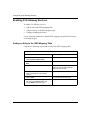
Adding an Entry to the IPEX Mapping Table
Complete the following steps to add an entry to the IPEX mapping table:
Site Manager Procedure
You do this
System responds
1. In the Configuration Manager window,
select Circuits > Edit Circuits.
The Circuit List window opens.
2. Choose an X.25 interface, then click on
Edit.
The Circuit Definition window opens.
3. Choose X25 Protocol > Service.
The X.25 Service Configuration window
appears. It lists all currently defined
network service records.
4. Choose the network service record you
want to configure for X.25 Gateway
services.
5. Click on Add.
The X.25 Service window opens.
6. Position your cursor in the Type parameter
bar, click on the Values button, and
choose IPEX as the service type.
(continued)
2-2
308649-14.00 Rev 00
Enabling X.25 Gateway
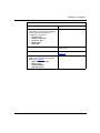
Site Manager Procedure (continued)
You do this
System responds
7. Edit the following parameters as
appropriate to your network. Use Help or
see the parameter descriptions in
Configuring X.25 Services.
• First PVC LCN
• Number of PVC LCN
• Service VC Type
• Window Size
• Packet Size
8. Click on OK.
The IPEX Mapping Table Configuration
window opens.
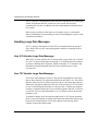
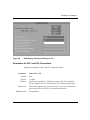
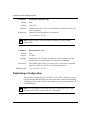
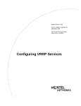
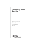
9. Click on Add.
The IPEX Mapping Add window opens
(Figure 2-1).
10. Set the following parameters. Click on
Help or see the parameter descriptions
beginning on page 2-4.
• Source Connection Type
• Mapping Type
• TCP Circuit Name
• TCP Header Type
308649-14.00 Rev 00
2-3
Configuring X.25 Gateway Services
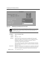
Figure 2-1.
IPEX Mapping Add Window for Source PVC
Note: This window is the same for PVC, SVC, and TCP source connections.
The Mapping Type is always Gateway. Values for the other parameters are
specific to your network.
Parameter:
Source Connection Type
Default:
None
Options:
PVC | SVC | TCP
Function:
Specifies the type of connection at the sending end of the original
message. PVC and SVC specify an X.25 Level 3 connection, either a
permanent virtual circuit or a switched virtual circuit. TCP is a
Transmission Control Protocol connection.
Source connection types PVC and SVC send to destination connection
type TCP. Source connection type TCP sends to destination connection
type PVC or SVC.
Instructions:
MIB Object ID:
2-4
Select PVC to specify an X.25 connection to a permanent virtual circuit.
Select SVC to specify an X.25 connection to a switched virtual circuit.
Select TCP to specify a Transmission Control Protocol connection.
1.3.6.1.4.18.3.5.15.2.1.4
308649-14.00 Rev 00
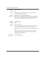
Enabling X.25 Gateway
Parameter:
Mapping Type
Default:
End_to_End
Options:
Local | End_to_End | Gateway
Function:
Specifies whether facilities, call user data, and M-bit and Q-bit support
terminate locally or are passed end-to-end. X.25 parameters that you
configure at the packet and service record level determine which facilities
are supported. The last option is to configure X.25 Gateway services.
If you set this parameter to Local, IPEX ports can support different packet
sizes at each end. You must also configure the Source X.121 Address
parameter for an SVC source connection type, and both Source and
Destination X.121 Address parameters for a TCP source connection type.
If you configure End-to-End mapping, all IPEX ports must have the same
packet and window size, because different packet sizes cause M-bit
support to malfunction.
If you set this parameter to Gateway you use X.25 Gateway services. X.25
terminates at the router interface, but allows you to configure one of three
message header types at the TCP application layer.
Instructions:
MIB Object ID:
308649-14.00 Rev 00
Choose Gateway.
1.3.6.1.4.1.18.3.5.15.2.1.16
2-5
Configuring X.25 Gateway Services
Parameter:
TCP Circuit Name
Default:
None
Options:
The name of this circuit. When you add a TCP circuit, the name is
displayed in the Add Circuit window.
Function:
Identifies this TCP circuit for mapping purposes.
Instructions:
Enter the name of the appropriate TCP circuit. If you do not know this
name, return to the main Configuration Manager window and click on the
connector you are configuring to reopen the Add Circuit window.
Parameter:
TCP Header Type
Default:
Short
Options:
None | Short | Long
Function:
Enables the Message Boundary Protocol. This bit marks the boundary of
TCP application data that is consistent with Gateway operation.
None means that there is no message header; Message Boundary Protocol
is off.
Short means that the message header contains a 2-byte length field.
Long means that the message header contains a 1-byte type, a 1-byte
version, and a 2-byte length field.
Instructions:
MIB Object ID:
2-6
Choose a header type.
1.3.6.1.4.1.18.3.5.15.2.1.22
308649-14.00 Rev 00
Enabling X.25 Gateway
Configuring Mapping Parameters
Complete the following steps to configure IPEX mapping parameters:
Site Manager Procedure
You do this
System responds
1. In the IPEX Mapping Add window, click
on OK.
The IPEX Mapping Parameters window
opens. Depending on your Source
Connection Type, Figure 2-2, Figure 2-3,
or Figure 2-4 opens.
2. Configure the parameters appropriate to
your connection type. Click on Help or see
the parameter descriptions beginning on
page 2-9. Parameters include:
• Source PVC LCN
• X.121 Called Address
• Remote IP Address
• Remote TCP Port Number
• Local TCP Port
• Destination Connection Type
• Destination PVC LCN
3. Click on OK.
The IPEX Mapping Table Configuration
window reopens.
4. Click on Done.
The X.25 Gateway configuration is
complete. You return to the X.25 Service
Configuration window.
5. To learn how to replicate this configuration You return to the main Configuration
Manager window.
for other PVC/TCP connections, see the
later section of the guide, “Replicating a
Configuration.” Otherwise, click on Done.
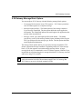
IPEX Mapping Parameters Windows
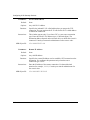
In the appropriate IPEX Mapping Parameters window, define a new mapping
entry by specifying source and destination addresses, the format of which depend
on whether the connection type is PVC, SVC, or TCP.
308649-14.00 Rev 00
2-7
Configuring X.25 Gateway Services
Figure 2-2.
IPEX Mapping Parameters Window for PVC
Figure 2-3.
IPEX Mapping Parameters Window for SVC
2-8
308649-14.00 Rev 00
Enabling X.25 Gateway
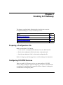
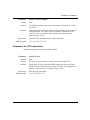
Figure 2-4.
IPEX Mapping Parameters Window for TCP
Parameters for PVC and SVC Connections
Parameter descriptions for PVC and SVC connections follow:
Parameter:
Source PVC LCN
Default:
None
Options:
1 to 4095
Function:
Specifies the inbound PVC LCN that you map to the TCP connection.
The port monitors the X.25 calls for this LCN to initiate the connection.
Instructions:
This window appears only if you chose PVC as your source connection
type. Enter the LCN of the PVC for this IPEX connection.
MIB Object ID:
308649-14.00 Rev 00
Not applicable
2-9
Configuring X.25 Gateway Services
Parameter:
Default:
None
Options:
Any valid X.121 address
Function:
Specifies the inbound X.121 called address that you map to the TCP
connection. The port monitors the X.25 calls for this X.121 called address
to initiate the connection.
Instructions:
This window appears only if you chose SVC as your source connection
type. Enter the called X.121 address (up to 15 decimal digits). The
destination address depends on the network device to which this circuit is
connected. Consult your network administrator for the correct value.
MIB Object ID:
Parameter:
1.3.6.1.4.18.3.5.15.2.1.6
Remote IP Address
Default:
None
Options:
Any valid IP address
Function:
Instructions:
MIB Object ID:
2-10
X.121 Called Address
Specifies the remote IP address used to establish a TCP connection to the
destination. You configure this parameter only when the source
connection type is SVC.
Enter the IP address of the remote connection. Use dotted-decimal
notation (for example, 1.1.1.1). Consult your network administrator for
the correct value.
1.3.6.1.4.1.18.3.5.15.2.1.12
308649-14.00 Rev 00
Enabling X.25 Gateway
Parameter:
Remote TCP Port Number
Default:
None
Options:
The TCP port number at the remote connection, a value between 12304
and 16399.
Function:
Instructions:
MIB Object ID:
Specifies the remote TCP port number used to establish a TCP connection
to the destination. The remote TCP port originates connections to the
local TCP port. You configure this parameter only when the source
connection type is SVC.
Enter the TCP port number for the remote connection.
1.3.6.1.4.1.18.3.5.15.2.1.13
Parameters for TCP Connections
Parameter descriptions for TCP connections follow:
Parameter:
Local TCP Port
Default:
None
Options:
The local TCP port number, a value between 12304 and 16399.
Function:
Instructions:
MIB Object ID:
308649-14.00 Rev 00
Specifies the TCP port in the local IPEX connection. This port accepts
inbound TCP connections from the remote TCP port. You configure this
parameter when the Source Connection Type is TCP.
Enter the TCP port number.
1.3.6.1.4.18.3.5.15.2.1.5
2-11
Configuring X.25 Gateway Services
Parameter:
Destination Connection Type
Default:
None
Options:
SVC | PVC
Function:
Instructions:
Specifies either SVC or PVC as the destination connection for this TCP
source connection.
Choose the value that applies to your network.
1.3.6.1.4.1.18.3.5.15.2.1.8
Note: Either the source or the destination connection type (but not both)
must be TCP.
Parameter:
Destination PVC LCN
Default:
None
Options:
1 to 4095
Function:
Instructions:
MIB Object ID:
Specifies the PVC LCN that you map to the TCP connection. The port
monitors the X.25 calls for this LCN to initiate the connection.
This window appears only if you chose PVC as your source connection
type. Enter the LCN of the PVC for this IPEX connection.
1.3.6.1.4.1.18.3.5.15.2.1.11
Replicating a Configuration
After you have configured one PVC-to-TCP or TCP-to-PVC connection, you can
copy that configuration and apply it to other connections, rather than configuring
the mappings one at a time. If you need to customize some of the connections, you
can edit them later.
Note: The Copy function works when one end of a connection is a PVC and
the other is TCP. It does not work with SVC connections.
2-12
308649-14.00 Rev 00
Enabling X.25 Gateway
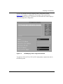
Use the Copy button in the IPEX Mapping Table Configuration window
(Figure 2-5) to replicate a configuration. The window is the same for both
PVC-to-TCP and TCP-to-PVC connections; the information the window displays
varies according to the configuration.
Figure 2-5.
IPEX Mapping Table Configuration Window
To replicate a PVC-to-TCP or TCP-to-PVC configuration, complete the tasks in
the following table.
308649-14.00 Rev 00
2-13
Configuring X.25 Gateway Services
Site Manager Procedure
You do this
System responds
1. Choose the configuration you want to
replicate, and click on Copy.
The IPEX Mapping Replication window
opens (Figure 2-6).
2. Set the following parameters. Click on
Help or see the parameter descriptions
beginning on page 2-18:
• Number of instances
• First LCN number
• First TCP port number
• TCP port number increment
2-14
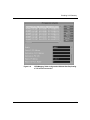
3. Click on OK.
The IPEX Mapping Table Configuration
window reopens (Figure 2-7 for
PVC-to-TCP, Figure 2-8 for TCP-to-PVC).
It now lists all of the connections you
have configured with the Copy button.
4. Click on Done.
You return to the X.25 Service
Configuration window.
5. Click on Done.
You return to the main Configuration
Manager window.
308649-14.00 Rev 00
Enabling X.25 Gateway
Figure 2-6.
IPEX Mapping Replication Window
308649-14.00 Rev 00
2-15
Configuring X.25 Gateway Services
Figure 2-7.
2-16
IPEX Mapping Table Configuration Window After Replicating
a PVC-to-TCP Connection
308649-14.00 Rev 00
Enabling X.25 Gateway
Figure 2-8.
308649-14.00 Rev 00
IPEX Mapping Table Configuration Window After Replicating
a TCP-to-PVC Connection
2-17
Configuring X.25 Gateway Services
Parameters for Replicating Connections
Parameter:
Default:
None
Options:
1 to 9 for a FRE2-040-32MB platform
1 to 31 for a FRE2-060-64MB platform
Function:
Specifies the number of connections to be replicated. The maximum
number of VCs per channel for the FRE2-040-32MB platform is 10, so
you can make up to 9 replicates; for the FRE1-060-64MB platform, the
maximum is 32, so you can make up to 31 replicates.
Instructions:
Enter the number of PVC-to-TCP or TCP-to-PVC replicate connections
you want to configure.
MIB Object ID:
Parameter:
Not applicable
First LCN number
Default:
None
Options:
2 to 10 for a FRE2-040-32MB platform
2 to 32 for a FRE2-060-64MB platform
Function:
Instructions:
MIB Object ID:
2-18
Number of Instances
Identifies the LCN number of the first PVC that will use the replicate
configuration. Each LCN number on a channel must be unique. The
options given above assume that you have assigned an LCN number of 1
for the PVC that you are using as the source for replicates.
Enter the LCN number.
Not applicable
308649-14.00 Rev 00
Enabling X.25 Gateway
Parameter:
First TCP port number
Default:
None
Options:
For a PVC-to-TCP connection, this value can be any valid port number.
For a TCP-to-PVC connection, this value must be within the range of
TCP ports reserved for Gateway service, 12,304 to 16,399.
Function:
Instructions:
MIB Object ID:
Parameter:
Identifies the number of the first TCP port that will use the replicate
configuration.
Enter the first TCP port number.
Not applicable
TCP port increment
Default:
None
Options:
Any integer. You can assign all of your replicates to the same port, in
which case you enter 0 for this parameter, or you can assign each its own
port by adding a value to each succeeding port number. In the example
given in Figure 2-6, each succeeding port is incremented by a value of 1.
Function:
Instructs the router how to increment port numbers assigned to each of the
replicate configurations.
Instructions:
MIB Object ID:
308649-14.00 Rev 00
Enter a value.
Not applicable
2-19
Index
A
acronyms, xi
D
adding an IPEX mapping entry, 2-2
DCE interface, 1-7
address, called X.121, 1-6
B
block, message, 1-13
destination circuit, definition of, 1-4
Destination Connection Type parameter, 2-12
Destination PVC LCN parameter, 2-12
DTE interface, 1-7
boundary, message, 1-12
E
C
Ethernet, 1-1
called X.121 address, 1-3, 1-6
SVC with, 1-6
SVC without, 1-7
F
channel, 1-7
fault, physical layer, 1-8
circuits, interface, 1-6
FDDI, 1-1
configuration file
preparing, 2-1
replicating, 2-12
Configuration Manager, 1-1
configuring IPEX mapping parameters, 2-7
congestion, 1-3, 1-5
connection
automatic reestablishment after a fault occurs, 1-8
from a LAPB terminal, 1-8
from a TCP/IP terminal, 1-9
from an X.25 terminal, 1-6
LAPB-to-TCP, 1-8
summary, 1-11
conventions, text, x
copying a configuration, 2-12
customer support, xii
308649-14.00 Rev 00
flow control, 1-3
G
Gateway, definition of, 1-1
H
header, message, 1-13
I
interface
circuit, 1-6
DCE, 1-7
DTE, 1-7
TCP, 1-4
Index-1
IP (Internet Protocol)
address, 1-4
IPEX
adding a mapping entry, 2-2
mapping parameters, configuring, 2-7
requirement to configure, 2-1
IPEX Mapping Add window, 2-4
message-based protocol, 1-12
MTU (Maximum Transmission Unit), 1-12
N
network
X.25, 1-1
IPEX Mapping Parameters window
PVC, 2-8
SVC, 2-8
TCP, 2-9
network topology
TCP/IP-to-LAPB, 1-2
TCP/IP-to-X.25, 1-2
IPEX Mapping Replication Window, 2-15
P
IPEX Mapping Table Configuration Window, 2-13
IPEX Mapping Table Configuration Window After
Replication
PVC-to-TCP Connection, 2-16
TCP-to-PVC Connection, 2-17
L
LAN media, 1-1
LAPB (Link Access Procedure Balanced)
connection to TCP, 1-8
description of, 1-2, 1-3
point-to-point connection, 1-1
protocol, 1-3
Packet Layer Protocol. See PLP
parameters, IPEX
Destination Connection Type, 2-12
Destination PVC LCN, 2-12
Local TCP Port, 2-11
Mapping Type, 2-5
Remote IP Address, 2-10
Remote TCP Port Number, 2-11
Source Connection Type, 2-4
Source PVC LCN, 2-9
TCP Circuit Name, 2-6
TCP Header Type, 2-6
X.121 Called Address, 2-10
permanent virtual circuit. See PVC
large data message, 1-12
PLP (Packet Layer Protocol), 1-3
LCN (logical channel number), 1-7
point-to-point connection, 1-1
Level 3 Packet Layer Protocol, 1-3
port, TCP, 1-4, 2-11
Local TCP Port parameter, 2-11
product support, xii
M
MAN (metropolitan area network) media, 1-1
mapping, 1-8, 1-10
Mapping Type parameter, 2-5
Maximum Transmission Unit (MTU), 1-12
MCT1 (Multichannel T1) interface, 1-1
message
block, 1-13
boundary, 1-12
header, 1-13
large, 1-12
Index-2
protocol
message-based (X.25) , 1-12
TCP, 1-3
TCP stack, 1-11
unstructured stream (TCP), 1-12
X.25 Level 2, 1-3
X.25 Level 3, 1-3
X.25 stack, 1-11
publications, hard copy, xii
PVC
configuring for X.25 Gateway, 1-3
definition of, 1-1
description of Gateway connection, 1-7
308649-14.00 Rev 00
Remote TCP Port Number parameter, 2-11
translation stream, 1-8
establishing (TCP initiated), 1-10
establishing (X.25 initiated), 1-5
X.25-to-TCP, 1-11
replicating a configuration, 2-12
Transmission Control Protocol. See TCP
R
Remote IP Address parameter, 2-10
transmission unit, maximum, 1-12
S
W
socket, 1-6, 1-7, 1-8
source circuit, definition of, 1-4
Source Connection Type parameter, 2-4
Source PVC LCN parameter, 2-9
stream protocol (TCP), 1-12
support, Nortel Networks, xii
SVC
configuring for X.25 Gateway, 1-3
definition of, 1-1
description of Gateway connection, 1-6
with called X.121 called address, 1-6
without called X.121 address, 1-7
T
T1 interface, 1-1
TCP
description of Gateway connection, 1-10
interface, 1-4
large data message, 1-12
port number, 1-4, 2-11
protocol stack, 1-11
socket, 1-6, 1-7
unstructured stream protocol, 1-12
TCP Circuit Name parameter, 2-6
TCP Header Type parameter, 2-6
TCP/IP-to-X.25 gateway, 1-2
windows
IPEX Mapping Add, 2-4
IPEX Mapping Parameters
PVC, 2-8
SVC, 2-8
TCP, 2-9
IPEX Mapping Replication, 2-15
IPEX Mapping Table Configuration, 2-13
IPEX Mapping Table Configuration After
Replication
PVC-to-TCP Connection, 2-16
TCP-to-PVC Connection, 2-17
X
X.121 called address, 1-3, 1-6, 1-7
X.121 Called Address parameter, 2-10
X.25
Gateway, definition of, 1-1
large data message, 1-12
Level 2 (LAPB-only) interface, 1-1, 1-3
Level 3 (PLP) interface, 1-1, 1-3
message-based protocol, 1-12
networks, 1-1
protocol stack, 1-11
PVC, 1-1
SVC, 1-1
VC, 1-1
technical publications, xii
technical support, xii
terminal, X.25, establishing connections from, 1-6
text conventions, x
token ring, 1-1
308649-14.00 Rev 00
Index-3