1
BayRS Version 14.00
Part No. 308617-14.00 Rev 00
September 1999
4401 Great America Parkway
Santa Clara, CA 95054
Configuring BSC Transport
Services
Copyright © 1999 Nortel Networks
All rights reserved. Printed in the USA. September 1999.
The information in this document is subject to change without notice. The statements, configurations, technical data,
and recommendations in this document are believed to be accurate and reliable, but are presented without express or
implied warranty. Users must take full responsibility for their applications of any products specified in this document.
The information in this document is proprietary to Nortel Networks NA Inc.
The software described in this document is furnished under a license agreement and may only be used in accordance
with the terms of that license. A summary of the Software License is included in this document.
Trademarks
NORTEL NETWORKS is a trademark of Nortel Networks.
Bay Networks, AN, and BN are registered trademarks and ARN, and ASN are trademarks of Nortel Networks.
All other trademarks and registered trademarks are the property of their respective owners.
Restricted Rights Legend
Use, duplication, or disclosure by the United States Government is subject to restrictions as set forth in subparagraph
(c)(1)(ii) of the Rights in Technical Data and Computer Software clause at DFARS 252.227-7013.
Notwithstanding any other license agreement that may pertain to, or accompany the delivery of, this computer
software, the rights of the United States Government regarding its use, reproduction, and disclosure are as set forth in
the Commercial Computer Software-Restricted Rights clause at FAR 52.227-19.
Statement of Conditions
In the interest of improving internal design, operational function, and/or reliability, Nortel Networks NA Inc. reserves
the right to make changes to the products described in this document without notice.
Nortel Networks NA Inc. does not assume any liability that may occur due to the use or application of the product(s)
or circuit layout(s) described herein.
Portions of the code in this software product may be Copyright © 1988, Regents of the University of California. All
rights reserved. Redistribution and use in source and binary forms of such portions are permitted, provided that the
above copyright notice and this paragraph are duplicated in all such forms and that any documentation, advertising
materials, and other materials related to such distribution and use acknowledge that such portions of the software were
developed by the University of California, Berkeley. The name of the University may not be used to endorse or
promote products derived from such portions of the software without specific prior written permission.
SUCH PORTIONS OF THE SOFTWARE ARE PROVIDED “AS IS” AND WITHOUT ANY EXPRESS OR
IMPLIED WARRANTIES, INCLUDING, WITHOUT LIMITATION, THE IMPLIED WARRANTIES OF
MERCHANTABILITY AND FITNESS FOR A PARTICULAR PURPOSE.
In addition, the program and information contained herein are licensed only pursuant to a license agreement that
contains restrictions on use and disclosure (that may incorporate by reference certain limitations and notices imposed
by third parties).
ii
308617-14.00 Rev 00
Nortel Networks NA Inc. Software License Agreement
NOTICE: Please carefully read this license agreement before copying or using the accompanying software or
installing the hardware unit with pre-enabled software (each of which is referred to as “Software” in this Agreement).
BY COPYING OR USING THE SOFTWARE, YOU ACCEPT ALL OF THE TERMS AND CONDITIONS OF
THIS LICENSE AGREEMENT. THE TERMS EXPRESSED IN THIS AGREEMENT ARE THE ONLY TERMS
UNDER WHICH NORTEL NETWORKS WILL PERMIT YOU TO USE THE SOFTWARE. If you do not accept
these terms and conditions, return the product, unused and in the original shipping container, within 30 days of
purchase to obtain a credit for the full purchase price.
1. License Grant. Nortel Networks NA Inc. (“Nortel Networks”) grants the end user of the Software (“Licensee”) a
personal, nonexclusive, nontransferable license: a) to use the Software either on a single computer or, if applicable, on
a single authorized device identified by host ID, for which it was originally acquired; b) to copy the Software solely
for backup purposes in support of authorized use of the Software; and c) to use and copy the associated user manual
solely in support of authorized use of the Software by Licensee. This license applies to the Software only and does not
extend to Nortel Networks Agent software or other Nortel Networks software products. Nortel Networks Agent
software or other Nortel Networks software products are licensed for use under the terms of the applicable Nortel
Networks NA Inc. Software License Agreement that accompanies such software and upon payment by the end user of
the applicable license fees for such software.
2. Restrictions on use; reservation of rights. The Software and user manuals are protected under copyright laws.
Nortel Networks and/or its licensors retain all title and ownership in both the Software and user manuals, including
any revisions made by Nortel Networks or its licensors. The copyright notice must be reproduced and included with
any copy of any portion of the Software or user manuals. Licensee may not modify, translate, decompile, disassemble,
use for any competitive analysis, reverse engineer, distribute, or create derivative works from the Software or user
manuals or any copy, in whole or in part. Except as expressly provided in this Agreement, Licensee may not copy or
transfer the Software or user manuals, in whole or in part. The Software and user manuals embody Nortel Networks’
and its licensors’ confidential and proprietary intellectual property. Licensee shall not sublicense, assign, or otherwise
disclose to any third party the Software, or any information about the operation, design, performance, or
implementation of the Software and user manuals that is confidential to Nortel Networks and its licensors; however,
Licensee may grant permission to its consultants, subcontractors, and agents to use the Software at Licensee’s facility,
provided they have agreed to use the Software only in accordance with the terms of this license.
3. Limited warranty. Nortel Networks warrants each item of Software, as delivered by Nortel Networks and properly
installed and operated on Nortel Networks hardware or other equipment it is originally licensed for, to function
substantially as described in its accompanying user manual during its warranty period, which begins on the date
Software is first shipped to Licensee. If any item of Software fails to so function during its warranty period, as the sole
remedy Nortel Networks will at its discretion provide a suitable fix, patch, or workaround for the problem that may be
included in a future Software release. Nortel Networks further warrants to Licensee that the media on which the
Software is provided will be free from defects in materials and workmanship under normal use for a period of 90 days
from the date Software is first shipped to Licensee. Nortel Networks will replace defective media at no charge if it is
returned to Nortel Networks during the warranty period along with proof of the date of shipment. This warranty does
not apply if the media has been damaged as a result of accident, misuse, or abuse. The Licensee assumes all
responsibility for selection of the Software to achieve Licensee’s intended results and for the installation, use, and
results obtained from the Software. Nortel Networks does not warrant a) that the functions contained in the software
will meet the Licensee’s requirements, b) that the Software will operate in the hardware or software combinations that
the Licensee may select, c) that the operation of the Software will be uninterrupted or error free, or d) that all defects
in the operation of the Software will be corrected. Nortel Networks is not obligated to remedy any Software defect that
cannot be reproduced with the latest Software release. These warranties do not apply to the Software if it has been (i)
altered, except by Nortel Networks or in accordance with its instructions; (ii) used in conjunction with another
vendor’s product, resulting in the defect; or (iii) damaged by improper environment, abuse, misuse, accident, or
negligence. THE FOREGOING WARRANTIES AND LIMITATIONS ARE EXCLUSIVE REMEDIES AND ARE
IN LIEU OF ALL OTHER WARRANTIES EXPRESS OR IMPLIED, INCLUDING WITHOUT LIMITATION ANY
WARRANTY OF MERCHANTABILITY OR FITNESS FOR A PARTICULAR PURPOSE. Licensee is responsible
308617-14.00 Rev 00
iii
for the security of its own data and information and for maintaining adequate procedures apart from the Software to
reconstruct lost or altered files, data, or programs.
4. Limitation of liability. IN NO EVENT WILL NORTEL NETWORKS OR ITS LICENSORS BE LIABLE FOR
ANY COST OF SUBSTITUTE PROCUREMENT; SPECIAL, INDIRECT, INCIDENTAL, OR CONSEQUENTIAL
DAMAGES; OR ANY DAMAGES RESULTING FROM INACCURATE OR LOST DATA OR LOSS OF USE OR
PROFITS ARISING OUT OF OR IN CONNECTION WITH THE PERFORMANCE OF THE SOFTWARE, EVEN
IF NORTEL NETWORKS HAS BEEN ADVISED OF THE POSSIBILITY OF SUCH DAMAGES. IN NO EVENT
SHALL THE LIABILITY OF NORTEL NETWORKS RELATING TO THE SOFTWARE OR THIS AGREEMENT
EXCEED THE PRICE PAID TO NORTEL NETWORKS FOR THE SOFTWARE LICENSE.
5. Government Licensees. This provision applies to all Software and documentation acquired directly or indirectly by
or on behalf of the United States Government. The Software and documentation are commercial products, licensed on
the open market at market prices, and were developed entirely at private expense and without the use of any U.S.
Government funds. The license to the U.S. Government is granted only with restricted rights, and use, duplication, or
disclosure by the U.S. Government is subject to the restrictions set forth in subparagraph (c)(1) of the Commercial
Computer Software––Restricted Rights clause of FAR 52.227-19 and the limitations set out in this license for civilian
agencies, and subparagraph (c)(1)(ii) of the Rights in Technical Data and Computer Software clause of DFARS
252.227-7013, for agencies of the Department of Defense or their successors, whichever is applicable.
6. Use of Software in the European Community. This provision applies to all Software acquired for use within the
European Community. If Licensee uses the Software within a country in the European Community, the Software
Directive enacted by the Council of European Communities Directive dated 14 May, 1991, will apply to the
examination of the Software to facilitate interoperability. Licensee agrees to notify Nortel Networks of any such
intended examination of the Software and may procure support and assistance from Nortel Networks.
7. Term and termination. This license is effective until terminated; however, all of the restrictions with respect to
Nortel Networks’ copyright in the Software and user manuals will cease being effective at the date of expiration of the
Nortel Networks copyright; those restrictions relating to use and disclosure of Nortel Networks’ confidential
information shall continue in effect. Licensee may terminate this license at any time. The license will automatically
terminate if Licensee fails to comply with any of the terms and conditions of the license. Upon termination for any
reason, Licensee will immediately destroy or return to Nortel Networks the Software, user manuals, and all copies.
Nortel Networks is not liable to Licensee for damages in any form solely by reason of the termination of this license.
8. Export and Re-export. Licensee agrees not to export, directly or indirectly, the Software or related technical data
or information without first obtaining any required export licenses or other governmental approvals. Without limiting
the foregoing, Licensee, on behalf of itself and its subsidiaries and affiliates, agrees that it will not, without first
obtaining all export licenses and approvals required by the U.S. Government: (i) export, re-export, transfer, or divert
any such Software or technical data, or any direct product thereof, to any country to which such exports or re-exports
are restricted or embargoed under United States export control laws and regulations, or to any national or resident of
such restricted or embargoed countries; or (ii) provide the Software or related technical data or information to any
military end user or for any military end use, including the design, development, or production of any chemical,
nuclear, or biological weapons.
9. General. If any provision of this Agreement is held to be invalid or unenforceable by a court of competent
jurisdiction, the remainder of the provisions of this Agreement shall remain in full force and effect. This Agreement
will be governed by the laws of the state of California.
Should you have any questions concerning this Agreement, contact Nortel Networks, 4401 Great America Parkway,
P.O. Box 58185, Santa Clara, California 95054-8185.
LICENSEE ACKNOWLEDGES THAT LICENSEE HAS READ THIS AGREEMENT, UNDERSTANDS IT, AND
AGREES TO BE BOUND BY ITS TERMS AND CONDITIONS. LICENSEE FURTHER AGREES THAT THIS
AGREEMENT IS THE ENTIRE AND EXCLUSIVE AGREEMENT BETWEEN NORTEL NETWORKS AND
LICENSEE, WHICH SUPERSEDES ALL PRIOR ORAL AND WRITTEN AGREEMENTS AND
COMMUNICATIONS BETWEEN THE PARTIES PERTAINING TO THE SUBJECT MATTER OF THIS
AGREEMENT. NO DIFFERENT OR ADDITIONAL TERMS WILL BE ENFORCEABLE AGAINST NORTEL
NETWORKS UNLESS NORTEL NETWORKS GIVES ITS EXPRESS WRITTEN CONSENT, INCLUDING AN
EXPRESS WAIVER OF THE TERMS OF THIS AGREEMENT.
iv
308617-14.00 Rev 00
Contents
Preface
Before You Begin .............................................................................................................xiii
Text Conventions .............................................................................................................xiv
Acronyms ......................................................................................................................... xv
Hard-Copy Technical Manuals ......................................................................................... xv
How to Get Help ..............................................................................................................xvi
Chapter 1
Starting BSC Transport Services
Preparing a Configuration File ........................................................................................1-1
Starting BTS ...................................................................................................................1-2
Deleting BTS from the Platform ......................................................................................1-2
Chapter 2
BSC Transport Services Overview
BSC Protocol ..................................................................................................................2-1
Hosts and Control Units ..................................................................................................2-2
Transmitting BSC Frames over TCP ...............................................................................2-2
Point-to-Point and Multipoint Configurations ...................................................................2-4
Point-to-Point Configuration .....................................................................................2-4
Multipoint Configuration ...........................................................................................2-4
Virtual Multipoint Configuration ................................................................................2-5
Chapter 3
Implementation Notes
BTS Interfaces ................................................................................................................3-1
Peer Routers ...................................................................................................................3-1
Connections to Control Units ..........................................................................................3-2
Line Details .....................................................................................................................3-3
308617-14.00 Rev 00
v
Chapter 4
Configuring BTS
Using the MIB Object ID .................................................................................................4-1
Accessing BTS Parameters ............................................................................................4-2
Globally Enabling and Disabling BTS .............................................................................4-2
Customizing BTS Interfaces ...........................................................................................4-3
Enabling and Disabling BTS Interfaces ....................................................................4-3
Creating Primary and Secondary Connections ........................................................4-4
Selecting an Interface Type ......................................................................................4-4
Setting the TCP Keepalive Parameters ....................................................................4-4
Deleting a BTS Interface ..........................................................................................4-6
Assigning Peer Routers ..................................................................................................4-6
Specifying the Peer IP Address ................................................................................4-6
Selecting the Connection Originator ........................................................................4-7
Setting the TCP Listen Ports ....................................................................................4-7
Enabling and Disabling BTS Peer Connections .......................................................4-8
Creating Connections to Control Units ...........................................................................4-8
Entering the Control Unit Address ...........................................................................4-9
Enabling and Disabling a Connection to a Control Unit ...........................................4-9
Editing Line Parameters ...............................................................................................4-10
Enabling the Line ...................................................................................................4-10
Setting the Transmission Frame Size .....................................................................4-10
Adjusting the Bisynchronous Timing Signals .........................................................4-11
Adjusting the Transmission Queues .......................................................................4-11
Setting the Control Character Mode .......................................................................4-12
Enabling and Disabling RTS and CTS Signal Detection ........................................4-12
vi
308617-14.00 Rev 00
Appendix A
Control Unit Addresses
Appendix B
BTS Parameters
BTS Global Parameters ................................................................................................. B-1
BTS Interface Parameters ............................................................................................. B-1
BTS Peer Table Parameters .......................................................................................... B-4
BOT CU Table Parameters ............................................................................................ B-6
Line Parameters ............................................................................................................ B-7
Appendix C
Default Values for BTS Parameters
Index
308617-14.00 Rev 00
vii
Figures
Figure 2-1.
Tunneling of BSC Frames ........................................................................2-3
Figure 2-2.
BTS Point-to-Point Configuration .............................................................2-4
Figure 2-3.
BTS Multipoint Configuration ...................................................................2-5
Figure 2-4.
BTS Virtual Multipoint Configuration ........................................................2-6
308617-14.00 Rev 00
ix
Tables
Table A-1.
Device Address Table for BSC3 ............................................................. A-1
Table C-1.
Interface Parameters ............................................................................. C-1
Table C-2.
Peer Entry Parameters .......................................................................... C-1
Table C-3.
Control Unit Parameters ......................................................................... C-2
Table C-4.
Line Parameters .................................................................................... C-2
308617-14.00 Rev 00
xi
Preface
This guide describes how to configure router software to transport binary
synchronous communication (BSC) data over a multiprotocol backbone network.
Before You Begin
If you configure and manage BSC Transport Services (BTS) for
Nortel Networks™ routers, you need to read this guide. Before using this guide,
you must complete the following procedures. For a new router:
•
Install the router (refer to the installation manual that came with your router).
•
Connect the router to the network and create a pilot configuration file (refer to
Quick-Starting Routers; Configuring BayStack Remote Access, or Connecting
ASN Routers to a Network).
Make sure you are running the latest version of Nortel Networks Site Manager and
router software. For instructions, refer to the upgrade guide.
308617-14.00 Rev 00
xiii
Configuring BSC Transport Services
Text Conventions
This guide uses the following text conventions:
angle brackets (< >)
Indicate that you choose the text to enter based on the
description inside the brackets. Do not type the
brackets when entering the command.
Example: If the command syntax is:
ping <ip_address>, you enter:
ping 192.32.10.12
bold text
Indicates text that you need to enter and command
names and options.
Example: Enter show ip {alerts | routes}
Example: Use the dinfo command.
italic text
Indicates file and directory names, new terms, book
titles, and variables in command syntax descriptions.
Where a variable is two or more words, the words are
connected by an underscore.
Example: If the command syntax is:
show at <valid_route>
valid_route is one variable and you substitute one value
for it.
screen text
Indicates system output, for example, prompts and
system messages.
Example: Set Trap Monitor Filters
separator ( > )
Shows menu paths.
Example: Protocols > IP identifies the IP option on the
Protocols menu.
vertical line ( | )
Separates choices for command keywords and
arguments. Enter only one of the choices. Do not type
the vertical line when entering the command.
Example: If the command syntax is:
show ip {alerts | routes}, you enter either:
show ip alerts or show ip routes, but not both.
xiv
308617-14.00 Rev 00
Preface
Acronyms
This guide uses the following acronyms:
ASCII
American Standard Code for Information Interchange
Bisync
binary synchronous communication
BOT
binary synchronous communication (BSC) over
TCP/IP; Bisync over TCP
BSC
binary synchronous communication
BTS
BSC Transport Services
CTS
clear to send
CU
control unit
EBCDIC
extended binary coded decimal interchange code
FEP
front-end processor
FTP
File Transfer Protocol
ISDN BRI
Integrated Services Digital Network Basic Rate
Interface
MTU
maximum transmission unit
RTS
request to send
TCP
Transmission Control Protocol
Hard-Copy Technical Manuals
You can print selected technical manuals and release notes free, directly from the
Internet. Go to support.baynetworks.com/library/tpubs/. Find the product for
which you need documentation. Then locate the specific category and model or
version for your hardware or software product. Using Adobe Acrobat Reader, you
can open the manuals and release notes, search for the sections you need, and print
them on most standard printers. You can download Acrobat Reader free from the
Adobe Systems Web site, www.adobe.com.
308617-14.00 Rev 00
xv
Configuring BSC Transport Services
You can purchase selected documentation sets, CDs, and technical publications
through the collateral catalog. The catalog is located on the World Wide Web at
support.baynetworks.com/catalog.html and is divided into sections arranged
alphabetically:
•
The “CD ROMs” section lists available CDs.
•
The “Guides/Books” section lists books on technical topics.
•
The “Technical Manuals” section lists available printed documentation sets.
How to Get Help
If you purchased a service contract for your Nortel Networks product from a
distributor or authorized reseller, contact the technical support staff for that
distributor or reseller for assistance.
If you purchased a Nortel Networks service program, contact one of the following
Nortel Networks Technical Solutions Centers:
xvi
Technical Solutions Center
Telephone Number
Billerica, MA
800-2LANWAN (800-252-6926)
Santa Clara, CA
800-2LANWAN (800-252-6926)
Valbonne, France
33-4-92-96-69-68
Sydney, Australia
61-2-9927-8800
Tokyo, Japan
81-3-5402-7041
308617-14.00 Rev 00
Chapter 1
Starting BSC Transport Services
The quickest way to begin using BTS is to enable it with default values for all
Bisync over TCP (BOT) interfaces and peers. The sections that follow describe
this procedure.
If you want to modify BOT parameters, refer to Chapter 4. See Appendix B for
complete descriptions of the BOT parameters as they appear in Site Manager.
Preparing a Configuration File
To enable BTS, read Configuring and Managing Routers with Site Manager and
1.
Open a configuration file.
2.
Specify router hardware if this is a local-mode configuration file. Nortel
Networks supports BTS on AN®, ASN™, ARN™, and BN® platforms.
3.
Choose a link module. For ASN routers, select the Dual Sync or the Dual
Sync/ISDN BRI net module. For BN routers, select the Octal Sync module.
For ARN routers, select the Serial adapter module or any of the following
expansion modules: TRI Serial, Ethernet/TRI Serial, Token Ring/TRI Serial,
or Token Ring/TRI Serial/DCM.
4.
Select the module connector on which you want to use BTS. You can
configure BTS on any COM port, not just COM1 and COM2.
Refer to Configuring and Managing Routers with Site Manager for instructions on
these procedures.
308617-14.00 Rev 00
1-1
Configuring BSC Transport Services
Starting BTS
To start BTS on an interface, select the synchronous connector on which you are
enabling BTS, and then follow the path described in this box:
Site Manager Path: From the WAN Protocols window that appears after
you select the connector, select BOT. Click on OK. The BOT Interfaces
window appears. Click on OK to accept the default values, or edit the
following parameters to customize the configuration (refer to Appendix B),
and then click on OK.
Enable: page B-1
Interface Attached To: page B-2
Interface Type: page B-2
TCP Keepalive Int: page B-3
TCP Keepalive Retry Timeout: page B-3
TCP Keepalive Retry Count: page B-4
Deleting BTS from the Platform
To delete BTS from all circuits on which it is currently configured, follow this
path:
Site Manager Path: Configuration Manager > Protocols > BOT > Delete BOT. A window
prompts: Do you REALLY want to delete BOT? Click on OK. Site Manager returns
you to the Configuration Manager window. BTS interfaces are no longer operating on the
platform.
1-2
308617-14.00 Rev 00
Chapter 2
BSC Transport Services Overview
BTS transmits binary synchronous communication (BSC) data over a
multiprotocol backbone network. A BTS configuration on the router executes the
protocol application Bisync over TCP (BOT). BTS operates on the Nortel
Networks AN, ARN, ASN, and BN routers running Software Version 11.01 or
later.
In the 1960s, IBM introduced the BSC protocol to transmit data between
mainframes and remote devices. Since then, IBM and many other vendors have
been using the BSC protocol with many types of computers and devices. BTS
users of BSC equipment can improve their networks by
•
•
•
Integrating BSC devices into an existing network of newer client/server
services
Eliminating direct BSC lines, which are expensive and often underused
Ensuring an extremely reliable and resilient method of data transmission via
TCP/IP
BSC Protocol
BSC typically operates over low-speed lines up to 19.2 Kb/s. The BSC protocol is
character-oriented and assumes 8-bit characters. It uses EBCDIC or, less
commonly, ASCII and other code sets for data transmission.
308617-14.00 Rev 00
2-1
Configuring BSC Transport Services
There are two main versions of the BSC protocol:
•
BSC3, Interactive (BSC 3270)
Its primary-secondary architecture specifies that the primary device is
responsible for initiating connections and controlling the transmission data.
•
BSC1, Batch (BSC 2780/3780)
It permits either side to initiate the connection and transfer data.
Nortel Networks currently supports the BSC3 protocol.
Hosts and Control Units
A BSC host is typically a mainframe computer running the BSC protocol. BSC
devices communicate with hosts via control units. A control unit (CU) manages
the BSC devices that connect to it.
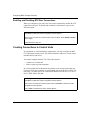
Transmitting BSC Frames over TCP
Data travels from one BSC device to another using two routers: a primary router
and a secondary router (Figure 2-1). A primary router has an interface to the host,
and a secondary router has an interface to the control units. Because you can
configure a single router interface as either primary or secondary, a router with
multiple interfaces can support both primary and secondary operations.
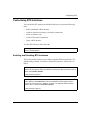
Figure 2-1 illustrates how a BSC device uses BTS to transmit data to a BSC host.
2-2
308617-14.00 Rev 00
BSC Transport Services Overview
Host
Front-end processor
FEP
CU
Primary
router
Secondary
router
Token
Ring
TCP/IP
T u n n e li n g
Ethernet
Figure 2-1.
BTS0001A
Tunneling of BSC Frames
BSC data travels between two routers using a process called tunneling. Tunneling
is independent of protocol differences between BSC devices and hosts.
The transfer process works like this:
1. A primary router interface transmits data to a secondary router interface.
2. The secondary router encapsulates the BSC data in a TCP/IP packet.
3. The secondary router transmits the packet over the IP network to the primary
router.
4. The primary router extracts the BSC data from the TCP/IP packet.
5. The primary router transmits the BSC data to the BSC host via a front-end
processor (FEP).
308617-14.00 Rev 00
2-3
Configuring BSC Transport Services
Point-to-Point and Multipoint Configurations
You can use BTS with point-to-point, multipoint, and virtual multipoint
configurations.
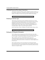
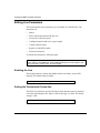
Point-to-Point Configuration
In a BTS point-to-point configuration, one control unit and one host connect via
one pair of routers (Figure 2-2).
Primary
router
Secondary
router
TCP/IP
Host
FEP
CU
BTS0002A
Figure 2-2.
BTS Point-to-Point Configuration
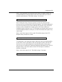
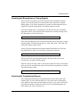
Multipoint Configuration
In a BTS multipoint configuration, up to 32 control units on the same line connect
to one host via one pair of routers (Figure 2-3).
2-4
308617-14.00 Rev 00
BSC Transport Services Overview
Primary
router
Secondary
router
TCP/IP
AN
Host
FEP
COM1
CU
CU
CU
BTS0004A
Figure 2-3.
BTS Multipoint Configuration
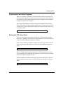
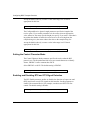
Virtual Multipoint Configuration
In a virtual BTS multipoint configuration, control units connect to secondary
routers, which link to the host via the primary router (Figure 2-4). Up to 32
control units can connect to the synchronous ports on each secondary router.
Using a virtual multipoint configuration, control units at different sites can
communicate with the host via the same line.
308617-14.00 Rev 00
2-5
Configuring BSC Transport Services
Primary
router
Secondary
router
TCP/IP
CU
Host
FEP
CU
Secondary
router
Secondary
router
CU
CU
CU
CU
CU
CU
CU
CU
CU
CU
BTS0005A
Figure 2-4.
2-6
BTS Virtual Multipoint Configuration
308617-14.00 Rev 00
Chapter 3
Implementation Notes
This chapter describes basic guidelines for implementing BTS on your network.
BTS Interfaces
You can enable the BOT application only on COM1 or COM2 interfaces on AN
routers. For ASN routers, select COM1 or COM2 on the Dual Sync module or
the Dual Sync/ISDN BRI module. For ARN routers, select the Serial adapter
module. For BN routers, select up to eight COM ports on the Octal Sync module.
When you enable BOT on an interface, you must specify whether the interface
•
•
Connects to a host (primary connection) or a control unit (secondary
connection)
Makes one (point-to-point) or many (multipoint) TCP connections
Only a primary interface can have multiple TCP connections.
Refer to Chapter 1 for information about starting BTS.
Peer Routers
When you enable BOT, you must assign at least one peer router. If you set up a
point-to-point BOT interface, you can assign only one peer router. If, however,
you set up a multipoint BOT interface, you can assign multiple peer routers, either
when you enable BOT or later.
308617-14.00 Rev 00
3-1
Configuring BSC Transport Services
When you assign a peer router, you must specify
•
•
•
The IP address of the peer router
Which of the two routers initiates the TCP connection
The TCP ports the routers use for BOT
Caution: Do not specify a TCP port that you have assigned to another
application.
You must also configure the peer router so that the information for the router pair
matches. For information about assigning peer routers, see Chapter 4 .
Connections to Control Units
You can connect up to 32 control units on the same line that links to a secondary
router. The actual performance on the line directly relates to the number of control
units you connect.
In a multipoint or virtual multipoint configuration, you must configure the BOT
CU table on the primary router. This table contains the address of each control
unit the host can access.
You cannot configure the BOT CU table if the interface
•
•
Connects to a control unit
Makes a point-to-point connection
For a virtual multipoint configuration, the primary router can have more than one
peer router. For each peer router, you must specify the control units that the host
can access.
3-2
308617-14.00 Rev 00
Implementation Notes
Line Details
Configuring line details for a bisynchronous line is similar to configuring line
details for a synchronous line. You need to specify the following information:
•
•
•
•
•
Maximum frame size the router can transmit on this line
Clock source for the timing signals
Speed of the clock source
Queue lengths for transmitting and receiving data
Control character mode (EBCDIC or ASCII)
For information about configuring line details, see Chapter 4 .
308617-14.00 Rev 00
3-3
Chapter 4
Configuring BTS
When you enable BTS, default values are in effect for all parameters (see
Appendix C). You can change these values to suit your network requirements. The
following sections describe your options.
Note: To edit BTS parameters, first configure at least one synchronous
interface (COM#) on an AN, ASN, ARN, or BN router. For ASN routers,
make sure you are using the Dual Sync or the Dual Sync/ISDN BRI network
module. For BN routers, use the Octal Sync module. For ARN routers, use the
Serial adapter module. To initially configure an interface, or to add additional
synchronous interfaces, see Configuring and Managing Routers with Site
Manager.
Using the MIB Object ID
The Technician Interface allows you to modify parameters by issuing set and
commit commands with the MIB object ID. This process is equivalent to
modifying parameters using Site Manager. For more information about using the
Technician Interface to access the MIB, refer to Using Technician Interface
Software.
Caution: The Technician Interface does not verify that the value you enter for
a parameter is valid. Entering an invalid value can corrupt your configuration.
308617-14.00 Rev 00
4-1
Configuring BSC Transport Services
Accessing BTS Parameters
In Site Manager, either of these paths leads you to the BTS parameters:
Site Manager Path 1: Configuration Manager > Protocols > BOT
Site Manager Path 2: Select a synchronous port that you have configured for BTS. The
Edit Connector window appears. Select Edit Circuit. The Circuit Definition window
appears. Use the BTS Circuit menu to access BTS parameters.
BTS parameters fall into the following categories:
•
Global (Enable and Disable)
•
Interface
•
Peer
•
Control Unit
•
Line
Globally Enabling and Disabling BTS
You can globally enable or disable the system software mechanisms that use the
BTS interface on a synchronous circuit.
The Disable option switches every BTS interface on the router into an inactive
state. The Enable option reinitializes every BTS interface on the router, with each
interface maintaining the most recent settings. The actual operating state of each
interface further depends on the current up/down state of the associated physical
circuit. To globally enable or disable BTS, follow this path:
Site Manager Path: Configuration Manager > Protocols > BOT > Global. The Edit BOT
Global Parameters window appears. Click on Values. Select Enable | Disable. Click on
OK.
Enable parameter: page B-1
4-2
308617-14.00 Rev 00
Configuring BTS
Customizing BTS Interfaces
You can edit the BTS settings on individual interfaces to perform the following
tasks:
•
Enable and disable a BTS interface
•
Attach an interface to primary or secondary connections
•
Select an interface type
•
Set the TCP keepalive parameters
•
Delete a BTS interface
To edit a BTS interface, follow this path:
Site Manager Path: Configuration Manager > Protocols > BOT > Interfaces. The BOT
Interface window appears.
Enabling and Disabling BTS Interfaces
The Enable parameter allows you to enable or disable BTS on an interface. The
default setting is Enable. To enable or disable BTS interfaces, follow Path 1 or
Path 2.
Site Manager Path 1: Configuration Manager > Protocols > BOT > Interfaces. The BOT
Interface window appears. Select the interface to edit from the upper left window. Click on
Values. Select Enable | Disable.
Enable parameter: page B-1
Site Manager Path 2: Select a port that you have configured for BTS. The Edit Connector
window appears. Select Edit Circuit. The Circuit Definition window appears. Select
Protocols or Group Protocols > Edit BOT > Interface. The Edit BOT Interface window
appears. Click on Values. Select Enable | Disable.
Enable parameter: page B-1
308617-14.00 Rev 00
4-3
Configuring BSC Transport Services
Creating Primary and Secondary Connections
The Interface Attached To parameter specifies whether this interface connects to a
host (primary connection) or a control unit (secondary connection). Specify either
Primary or Secondary. The router does not provide a default for this setting.
Site Manager: Interface Attached To: page B-2
Selecting an Interface Type
The Interface Type parameter specifies whether the interface has one or many
TCP connections. Point-to-point provides one TCP connection to the peer router.
Multipoint provides many TCP connections to one or more peer routers. A
multipoint connection can also be one TCP connection with multiple CUs. A
primary interface can have either a point-to-point or multipoint connection. A
secondary interface can have only a point-to-point connection.
Specify either Point-to-Point or Multipoint. The default setting is Point-to-Point.
Site Manager: Interface Type: page B-2
Setting the TCP Keepalive Parameters
The TCP Keepalive Interval parameter specifies how often the router sends a
signal to the peer router to check that the peer router is working correctly and can
receive messages. You enable the parameter by specifying a nonzero value.
When a keepalive packet goes unacknowledged by the remote peer,
retransmission begins at the local peer router. You should tune the keepalive
interval based on the total time it takes to send and receive acknowledgment from
the remote peer.
Since keepalive packets are only sent on idle lines, increasing the keepalive
interval may decrease the cost of an idle network. In busy networks, the keepalive
interval is not necessary. Frequent traffic for TCP transmission performs the same
function as a keepalive setting.
4-4
308617-14.00 Rev 00
Configuring BTS
Enter a value appropriate for the network in the range 0 to 86400 seconds. We
recommend that you set this parameter to the same value on the peer router to
maintain synchronization. The default setting is 120 seconds.
Site Manager: TCP Keepalive Int (sec): page B-3
The TCP Keepalive Retry Timeout parameter specifies the maximum time
between successive retransmissions of keepalive packets. If an acknowledgment is
not received by the local peer router within the TCP keepalive retry timeout, the
local peer router retransmits the keepalive packet. The router continues to
retransmit keepalive packets at every TCP keepalive retry timeout until it receives
an acknowledgment from the remote peer, or until TCP reaches the keepalive retry
count setting.
Enter a value in the range 0 to 600 seconds. The default setting for the TCP
Keepalive Retry timeout is 4 seconds.
Site Manager: TCP Keepalive Retry Timeout (sec): page B-3
TCP determines a lost connection (either a failed link with no rerouting possible,
or the remote router is unavailable) when TCP attempts to deliver data. If TCP
does not receive an acknowledgment to transmitted keepalive packets after a
series of retries, it declares the connection inoperable and informs BTS. The TCP
Keepalive Retry Count is the number of times TCP attempts to establish or
maintain a connection.
Enter a value in the range 0 to 99. The default setting is 5 attempts.
Site Manager: TCP Keepalive Retry Count (sec): page B-4
308617-14.00 Rev 00
4-5
Configuring BSC Transport Services
Deleting a BTS Interface
To delete a BTS interface from its associated physical circuit, follow this path:
Site Manager Path: At the Configuration Manager window, select Circuits > Delete
Circuit. The Circuit List window appears. Select the interface to delete from the upper left
window. Click on Delete. The Delete Circuit window appears. Click on Delete.
Note: Whenever you delete a BOT interface, the router will continue to run
TCP if other applications on the router require TCP services.
Assigning Peer Routers
When you enable BTS on a router, you must assign at least one peer router. If you
set up a point-to-point BTS interface, you can assign only one peer router. If,
however, you set up a multipoint BTS interface, you can assign multiple peer
routers, either when you enable BTS or later. To assign a peer router, follow this
path:
Site Manager Path: Configuration Manager > Protocols > BOT > Interfaces. Select Peer
Table. The BOT Peer Table Configuration window appears. Click on Add. The Add BOT
Peer Entry window appears.
Configure the parameters in the window. Click on OK. The BOT Peer Table Configuration
window reappears with the peer entry that you just added.
When you configure a peer router, the software automatically enables the TCP
connection to that router. To later disable a connection to a peer router, refer to
“Enabling and Disabling BTS Peer Connections,” later in this section.
Specifying the Peer IP Address
The Peer IP Address parameter allows you to specify the IP address of a peer
router. Use any valid IP address in dotted decimal notation.
Site Manager: Peer IP Address parameter: page B-4
4-6
308617-14.00 Rev 00
Configuring BTS
Selecting the Connection Originator
When you configure a connection, you need to decide which router initiates the
TCP connection, either the local peer router or the remote peer router. If the local
peer router is the TCP connection initiator, then you configure it as Self and you
configure the remote peer as Partner.
The Connection Originator parameter setting controls whether the local router
(Self) or the remote peer router (Partner) initiates the TCP connection. Select Self
or Partner. Be sure to set this parameter on the peer router to the other value. There
is no default setting.
Site Manager: Connection Originator parameter: page B-5
Setting the TCP Listen Ports
The Local TCP Listen Port parameter specifies the TCP port number that this
router uses to establish a TCP connection. This parameter is active only when you
set the Connection Originator parameter to Partner.
Enter a valid, available port number for this router in the range 1000 to 9999. Be
sure to use the same value for the Peer TCP Listen Port parameter on the peer
router.
Site Manager: Local TCP Listen Port parameter: page B-5
The Peer TCP Listen Port parameter specifies the TCP port that the peer router
uses to establish a TCP connection. This parameter is active only when you set the
connection originator parameter to Self.
Enter an available port number for the peer router in the range 1000 to 9999. Be
sure to use the same value for the Local TCP Listen Port parameter on the peer
router.
Site Manager: Peer TCP Listen Port parameter: page B-5
308617-14.00 Rev 00
4-7
Configuring BSC Transport Services
Enabling and Disabling BTS Peer Connections
When you configure a peer router, the local router automatically enables the TCP
connection to the peer. To disable and reenable the connection to a peer router,
follow this path:
Site Manager Path: Configuration Manager > Protocols > BOT > Interfaces. Click on
Peer Table. The BOT Peer Table Configuration window appears.
Select a peer connection from the list window. Click on Values. Select Enable | Disable.
Click on Apply.
Enable parameter: page B-4.
Creating Connections to Control Units
In a multipoint or virtual multipoint configuration, you must configure the BOT
CU Table on the primary router. This table contains the addresses of each control
unit that the host can access.
You cannot configure the BOT CU Table if the interface
•
•
Connects to a control unit
Makes a point-to-point connection
In a virtual multipoint configuration, the primary router can have more than one
peer router. Each peer router has a corresponding entry in the BOT Peer Table. For
each entry, you must specify the control units that the host can access. To access
the CU Table, follow this path:
Site Manager Path: Configuration Manager > Protocols > BOT > Interfaces. Click on
Peer Table. The BOT Peer Table Configuration window appears.
Select a peer connection from the list window. Click on CU Table. The BOT CU Table
Configuration window appears.
Click on Add. The Add BOT CU Entry window appears.
4-8
308617-14.00 Rev 00
Configuring BTS
Entering the Control Unit Address
The control unit address is a hexadecimal value in the range 0x40 to 0xFE. For
guidelines, see Appendix A.
Site Manager: Control Unit Address (hex) parameter: page B-6
When you add an entry to the BOT CU Table, the software automatically enables
the TCP connection to that control unit. To disable the connection later, see the
next section, “Enabling and Disabling a Connection to a Control Unit.”
Enabling and Disabling a Connection to a Control Unit
You can disable or reenable the connection to a control unit with the Enable
parameter. If you disable the connection to the control unit, the TCP connection
remains active, but unused until you reenable the connection. The default setting
is Enable. To access this parameter, follow this path:
Site Manager Path: Configuration Manager > Protocols > BOT > Interfaces. Click on
Peer Table. The BOT Peer Table Configuration window appears.
Select a peer connection from the list window. Click on CU Table. The BOT CU Table
Configuration window appears. Select a control unit from the list of entries. Select the
Enable parameter. Click on Values. Select Enable | Disable.
Click on Apply. Click on Done.
Enable parameter: page B-4.
308617-14.00 Rev 00
4-9
Configuring BSC Transport Services
Editing Line Parameters
This section describes the parameters you can modify for each BTS line. The
parameters are
•
Enable
•
MTU (maximum transmission unit) size
•
Clock source and clock speed
•
Configured transmit and receive queue length
•
Control character mode
•
Request to send (RTS) enable
•
External clock speed
To edit the line parameters, follow this path:
Site Manager Path: Select a port that you have configured for BTS. The Edit Connector
window appears. Select Edit Line. The Edit BISYNC Parameters window appears. Edit
the line parameters. Click on OK to save the changes.
Enabling the Line
The Enable parameter enables and disables the line on which you have BTS
running. The default setting is Enable.
Site Manager: Enable parameter: page B-6
Setting the Transmission Frame Size
The MTU Size parameter specifies the largest frame that the router can transmit
across this bisynchronous line. Enter a value in the range 1 to 4568. The default
setting is 1580.
Site Manager: MTU Size parameter: page B-7
4-10
308617-14.00 Rev 00
Configuring BTS
Adjusting the Bisynchronous Timing Signals
The Clock Source parameter specifies the origin of the bisynchronous timing
signals. If you set this parameter to Internal, this router supplies the required
timing signals. If you set this parameter to External, an external network device
supplies the required timing signals. The default setting is External.
Select the clocking mode, as appropriate for the network. Be sure to attach the
appropriate cable to your router for either an internal or external clocking source
(for information, see the Cable Guide).
Site Manager: Clock Source parameter: page B-7
The Clock Speed parameter sets the clock speed when you use the router to supply
clocking signals. The allowable settings are: 1200, 2400, 4800, 7200, 9600, and
19200. The default setting is 9600.
Set the Clock Speed parameter to the desired data transmission rate across the
bisynchronous line, and set the Clock Source parameter to Internal.
Site Manager: Clock Speed parameter: page B-8
The External Clock Speed parameter sets the clock speed when you use an
external source to supply clocking signals.
Enter the value in the range 1200 to 19200 bits/sec that most closely corresponds
to the speed of the external clock, and set the Clock Source parameter to external.
The default setting is 9600.
Site Manager: External Clock Speed parameter: page B-9
Adjusting the Transmission Queues
The Configured Transmit Queue Length parameter specifies the length of the
transmit queue. If you set this parameter to 0, the router selects an appropriate
value; otherwise, the router uses the length you specify. If you enter a value that is
larger than the number of buffers the router reserves for transmitting data, the
router reduces the value to a usable size.
308617-14.00 Rev 00
4-11
Configuring BSC Transport Services
Accept the default value (0) or enter a value in the range 0 to 255 that is
appropriate for this line.
Site Manager: Configured Transmit Q Length parameter: page B-8
The Configured Receive Queue Length parameter specifies the length of the
receive queue. If you set this parameter to 0, the router selects an appropriate
value; otherwise, the router uses the length you specify. If you enter a value that is
larger than the number of buffers the router reserves for receiving data (the
compiled ring size), the router reduces the value to the compiled ring size.
Accept the default value (0) or enter a value in the range 0 to 255 that is
appropriate for this line.
Site Manager: Configured Receive Q Length parameter: page B-8
Setting the Control Character Mode
The Control Character Mode parameter specifies the code set that the BSC
protocol uses. The bisynchronous link layers use control characters to identify
frames. EBCDIC is more common than ASCII.
Select EBCDIC or ASCII. The default setting is EBCDIC.
Site Manager: Control Character Mode parameter: page B-9
Enabling and Disabling RTS and CTS Signal Detection
The RTS Enable parameter enables or disables the detection of request-to-send
(RTS) and clear-to-send (CTS) signals on this interface. Set this parameter to
enable if the connected device (for example, a modem) uses RTS/CTS flow
control. The default setting is Disable.
Site Manager: RTS Enable parameter: page B-9
4-12
308617-14.00 Rev 00
Appendix A
Control Unit Addresses
To specify a connection to a control unit, you enter the control unit’s address.
Table A-1 shows the addresses to use for BSC3.
Table A-1.
Device Address Table for BSC3
Control Unit or
Device Position
Control Unit Address
0
0x40
1
0xC1
2
0xC2
3
0xC3
4
0xC4
5
0xC5
6
0xC6
7
0xC7
8
0xC8
9
0xC9
10
0x4A
11
0x4B
12
0x4C
13
0x4D
14
0x4E
15
0x4F
16
0x50
(continued)
308617-14.00 Rev 00
A-1
Configuring BSC Transport Services
Table A-1.
A-2
Device Address Table for BSC3 (continued)
Control Unit or
Device Position
Control Unit Address
17
0xD1
18
0xD2
19
0xD3
20
0xD4
21
0xD5
22
0xD6
23
0xD7
24
0xD8
25
0xD9
26
0x5A
27
0x5B
28
0x5C
29
0x5D
30
0x5E
31
0x5F
308617-14.00 Rev 00
Appendix B
BTS Parameters
BTS Global Parameters
Parameter: Enable
Path:
Default:
Options:
Function:
Instructions:
MIB Object ID:
Configuration Manager > Protocols > BOT > Global
Enable
Enable | Disable
Enables or disables BOT on this interface.
Select Enable or Disable.
1.3.6.1.4.1.18.3.5.18.1.2
BTS Interface Parameters
Parameter: Enable
Path:
Default:
Options:
Function:
Instructions:
MIB Object ID:
Configuration Manager > Protocols > BOT > Interfaces
Enable
Enable | Disable
Enables or disables BOT on this interface.
Select Enable or Disable.
1.3.6.1.4.1.18.3.5.18.2.1.2
308617-14.00 Rev 00
B-1
Configuring BSC Transport Services
Parameter: Interface Attached To
Path:
Default:
Options:
Function:
Configuration Manager > Protocols > BOT > Interfaces
None
Primary | Secondary
Specifies whether this interface connects to a host (primary connection) or a
control unit (secondary connection).
Instructions: Select Primary or Secondary.
MIB Object ID: 1.3.6.1.4.1.18.3.5.18.2.1.7
Parameter: Interface Type
Path:
Default:
Options:
Function:
Configuration Manager > Protocols > BOT > Interfaces
Point-to-Point
Point-to-Point | Multipoint
Specifies whether the interface has one or many TCP connections.
Point-to-point provides one TCP connection to the peer router. Multipoint
provides many TCP connections to one or more peer routers. A multipoint
connection can also be one TCP connection with multiple CUs. A primary
interface can have either a point-to-point or multipoint connection. A secondary
interface can have only a point-to-point connection.
Instructions: If this is a primary connection, select point-to-point or multipoint; if this is a
secondary connection, accept point-to-point.
MIB Object ID: 1.3.6.1.4.1.18.3.5.18.2.1.6
B-2
308617-14.00 Rev 00
BTS Parameters
Parameter: TCP Keepalive Int (sec)
Path:
Default:
Options:
Function:
Configuration Manager > Protocols > BOT > Interfaces
120
0 to 86400 seconds
Specifies how often the router sends a signal to the peer router to check that the
peer router is working correctly and can receive messages.
When a keepalive packet goes unacknowledged by the remote peer,
retransmission begins at the local peer router. You should tune the keepalive
interval based on the total time it takes to send and receive acknowledgment
from the remote peer.
Since keepalive packets are only sent on idle lines, increasing the keepalive
interval may decrease the cost of an idle network. In busy networks, the
keepalive interval is not necessary. Frequent traffic for TCP transmission
performs the same function as a keepalive setting.
Instructions: Enter a value appropriate for the network. We recommend that you set this
parameter to the same value on the peer router to maintain synchronization.
MIB Object ID: 1.3.6.1.4.1.18.3.5.18.2.1.9
Parameter: TCP Keepalive Retry Timeout (sec)
Path:
Default:
Options:
Function:
Configuration Manager > Protocols > BOT > Interfaces
4
0 to 600 seconds
Specifies the maximum time between successive retransmissions of keepalive
packets. If an acknowledgment is not received by the local peer router within the
TCP keepalive retry timeout, the local peer router retransmits the keepalive
packet. The router continues to retransmit keepalive packets at every TCP
keepalive retry timeout until it receives an acknowledgment from the remote
peer, or until TCP reaches the keepalive retry count setting.
Instructions: Enter a value in the range 0 to 600.
MIB Object ID: 1.3.6.1.4.1.18.3.5.18.2.1.10
308617-14.00 Rev 00
B-3
Configuring BSC Transport Services
Parameter: TCP Keepalive Retry Count
Path:
Default:
Options:
Function:
Configuration Manager > Protocols > BOT > Interfaces
5
0 to 99 seconds
Specifies the number of TCP attempts to establish or maintain a connection. If
TCP does not receive an acknowledgment after a series of retries, it declares the
connection inoperable and informs BOT.
Instructions: Enter a value in the range 0 to 99 seconds.
MIB Object ID: 1.3.6.1.4.1.18.3.5.18.2.1.11
BTS Peer Table Parameters
Parameter: Enable
Path:
Default:
Options:
Function:
Instructions:
MIB Object ID:
Configuration Manager > Protocols > BOT > Interfaces > Peer Table
Enable
Enable | Disable
Enables or disables the TCP connection to this peer router interface.
Select Enable or Disable.
1.3.6.1.4.1.18.3.5.18.3.1.2
Parameter: Peer IP Address
Path:
Default:
Options:
Function:
Instructions:
MIB Object ID:
B-4
Configuration Manager > Protocols > BOT > Interfaces > Peer Table > Add
None
Any valid IP address
Specifies the IP address of the peer router.
Enter the peer router’s IP address in dotted decimal notation.
1.3.6.1.4.1.18.3.5.18.3.1.5
308617-14.00 Rev 00
BTS Parameters
Parameter: Connection Originator
Path:
Default:
Options:
Function:
Configuration Manager > Protocols > BOT > Interfaces > Peer Table > Add
None
Self | Partner
Determines whether this router (Self) or the peer router (Partner) initiates the
TCP connection.
Instructions: Select Self or Partner. Be sure to set this parameter on the peer router to the
other value.
MIB Object ID: 1.3.6.1.4.1.18.3.5.18.3.1.6
Parameter: Local TCP Listen Port
Path:
Default:
Options:
Function:
Configuration Manager > Protocols > BOT > Interfaces > Peer Table > Add
None
1000 to 9999
Specifies the TCP port number that this router uses to establish a TCP
connection. This parameter is active only when you set the Connection
Originator parameter to Partner.
Instructions: Enter a valid, available port number for this router. Be sure to use the same value
for the Peer TCP Listen Port parameter on the peer router.
MIB Object ID: 1.3.6.1.4.1.18.3.5.18.3.1.7
Parameter: Peer TCP Listen Port
Path:
Default:
Options:
Function:
Configuration Manager > Protocols > BOT > Interfaces > Peer Table > Add
None
1000 to 9999
Specifies the TCP port that the peer router uses to establish a TCP connection.
This parameter is active only when you set the Connection Originator parameter
to Self.
Instructions: Enter a valid, available port number for the peer router. Be sure to use the same
value for the Local TCP Listen Port parameter on the peer router.
MIB Object ID: 1.3.6.1.4.1.18.3.5.18.3.1.8
308617-14.00 Rev 00
B-5
Configuring BSC Transport Services
BOT CU Table Parameters
Parameter: Control Unit Address
Path: Configuration Manager > Protocols > BOT > Interfaces > Peer Table >
CU Table > Add
Default: None
Options: 0x40 to 0xFE
Function: Specifies the address of the control unit.
Instructions: Enter the address of the control unit, in hexadecimal format.
MIB Object ID: 1.3.6.1.4.1.18.3.5.18.3.1.8
Parameter: Enable
Path: Configuration Manager > Protocols > BOT > Interfaces > Peer Table >
CU Table
Default: Enable
Options: Enable | Disable
Function: Enables or disables this control unit.
Instructions: Select Enable or Disable.
MIB Object ID: 1.3.6.1.4.1.18.3.5.18.4.1.2
B-6
308617-14.00 Rev 00
BTS Parameters
Line Parameters
Parameter: Enable
Path:
Default:
Options:
Function:
Instructions:
MIB Object ID:
Configuration Manager > Select connector > Edit Line
Enable
Enable | Disable
Enables or disables this line.
Select Enable or Disable.
1.3.6.1.4.1.18.3.4.27.1.1.2
Parameter: MTU Size
Path:
Default:
Options:
Function:
Configuration Manager > Select connector > Edit Line
1580
1 to 4568 bytes
Specifies the largest frame that the router can transmit across this bisynchronous
line.
Instructions: Specify a value appropriate for the network.
MIB Object ID: 1.3.6.1.4.1.18.3.4.27.1.1.4
Parameter: Clock Source
Path:
Default:
Options:
Function:
Configuration Manager > Select connector > Edit Line
External
External | Internal
Specifies the origin of the bisynchronous timing signals. If you set this
parameter to Internal, the router supplies the required timing signals. If you set
this parameter to External, an external network device supplies the required
timing signals.
Instructions: Select the clocking mode, as appropriate for the network. Be sure to attach the
appropriate cable to your router for an internal or external clocking source (see
the cable guide for information).
MIB Object ID: 1.3.6.1.4.1.18.3.4.27.1.1.7
308617-14.00 Rev 00
B-7
Configuring BSC Transport Services
Parameter: Clock Speed
Path:
Default:
Options:
Function:
Instructions:
Configuration Manager > Select connector > Edit Line
9600
1200 B | 2400 B | 4800 B | 7200 B | 9600 B | 19200 B
Sets the clock speed when you use the router to supply clocking signals.
Set the Clock Speed parameter to the desired data transmission rate across the
bisynchronous line, and set the Clock Source parameter to Internal.
MIB Object ID: 1.3.6.1.4.1.18.3.4.27.1.1.8
Parameter: Configured Transmit Q Length
Path:
Default:
Options:
Function:
Configuration Manager > Select connector > Edit Line
0
0 to 255
Specifies the length of the transmit queue. If you set this parameter to 0, the
router selects an appropriate value; otherwise, the router uses the length you
specify. If you enter a value that is larger than the number of buffers the router
reserves for transmitting data (the compiled ring size), the router reduces the
value to the compiled ring size.
Instructions: Accept the default or enter a value that is appropriate for this line.
MIB Object ID: 1.3.6.1.4.1.18.3.4.27.1.1.10
Parameter: Configured Receive Q Length
Path:
Default:
Options:
Function:
Configuration Manager > Select connector > Edit Line
0
0 to 255
Specifies the length of the receive queue. If you set this parameter to 0, the
router selects an appropriate value; otherwise, the router uses the length you
specify. If you enter a value that is larger than the number of buffers the router
reserves for receiving data (the compiled ring size), the router reduces the value
to the compiled ring size.
Instructions: Accept the default or enter a value that is appropriate for this line.
MIB Object ID: 1.3.6.1.4.1.18.3.4.27.1.1.11
B-8
308617-14.00 Rev 00
BTS Parameters
Parameter: Control Character Mode
Path:
Default:
Options:
Function:
Configuration Manager > Select connector > Edit Line
EBCDIC
EBCDIC | ASCII
Specifies the code set that the BSC protocol uses. The BSC link layers use
control characters to identify frames. EBCDIC is more common than ASCII.
Instructions: Select EBCDIC or ASCII.
MIB Object ID: 1.3.6.1.4.1.18.3.4.27.1.1.12
Parameter: External Clock Speed
Path:
Default:
Options:
Function:
Instructions:
Configuration Manager > Select connector > Edit Line
9600
1200 to 19200 bits/sec
Sets the clock speed when you use an external source to supply clocking signals.
Enter the value that most closely corresponds to the speed of the external clock,
and set the Clock Source parameter to External.
MIB Object ID: 1.3.6.1.4.1.18.3.4.27.1.1.15
Parameter: RTS Enable
Path:
Default:
Options:
Function:
Configuration Manager > Select connector > Edit Line
Disable
Enable | Disable
Enables or disables the detection of request to send (RTS) and clear to send
(CTS) signals on this interface.
Instructions: Set this parameter to Enable if the connected device (for example, a modem)
uses RTS/CTS flow control.
MIB Object ID: 1.3.6.1.4.1.18.3.4.27.1.1.14
308617-14.00 Rev 00
B-9
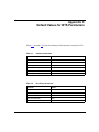
Appendix C
Default Values for BTS Parameters
Tables C-1 through C-4 list the Site Manager default parameter settings for BTS.
Table C-1.
Interface Parameters
Parameter
Default
Enable
Enable
Interface Attached To
None
Interface Type
Point-to-Point
TCP Keepalive Int(erval)
120 seconds
TCP Keepalive Retry Timeout
4 seconds
TCP Keepalive Retry Count
5
Table C-2.
Peer Entry Parameters
Parameter
Default
Peer IP Address
None
Connection Originator
None
Local TCP Listen Port
None
Peer TCP Listen Port
None
Enable
Enable
308617-14.00 Rev 00
C-1
Configuring BSC Transport Services
Table C-3.
Parameter
Default
Control Unit Address
None
Enable
Enable
Table C-4.
C-2
Control Unit Parameters
Line Parameters
Parameter
Default
Enable
Enable
MTU Size
1580
Clock Source
External
Clock Speed
9600
Configured Transmit Q Length
0
Configured Receive Q Length
0
Control Character Mode
EBCDIC
RTS Enable
Disabled
External Clock Speed
9600
308617-14.00 Rev 00
Index
A
acronyms, xv
assigning peer routers, 3-1, 4-6
B
BOT (Bisync over TCP)
control unit connection parameters
Control Unit Address, 4-9, B-6
Enable, 4-9, B-6
global parameters
Enable and Disable, 4-2
interface parameters
default values, C-1
Enable, 4-2, 4-3, B-1
Interface Attached To, 4-4, B-2
Interface Type, 4-4, 4-5, B-2
TCP Keepalive Int, 4-5, B-3
TCP Keepalive Retry Count, 4-5, B-4
TCP Keepalive Retry Timeout, 4-5, B-3
line parameters
Clock Source, 4-11, B-7
Clock Speed, 4-11, B-8
Configured Receive Q Length, 4-12, B-8
Configured Transmit Q Length, 4-12, B-8
Control Character Mode, 4-12, B-9
Enable, 4-10, B-7
External Clock Speed, 4-11, B-9
MTU Size, 4-10, B-7
RTS Enable, 4-12, B-9
peer table parameters
Connection Originator, 4-7, B-5
Enable, 4-8, B-4
Local TCP Listen Port, 4-7, B-5
Peer IP Address, 4-6, B-4
Peer TCP Listen Port, 4-7, B-5
308617-14.00 Rev 00
BSC (binary synchronous communication)
host, 2-2
protocol, 2-1
BSC1 overview, 2-2
BSC3 overview, 2-2
BTS (BSC Transport Services)
parameters, accessing BOT in Site Manager, 4-2
preparing a configuration file for, 1-1
supported network modules, 4-1
supported routers, 1-1, 4-1
C
Clock Source parameter, 4-11, B-7
Clock Speed parameter, 4-11, B-8
Configured Receive Q Length parameter, 4-12, B-8
Configured Transmit Q Length parameter, 4-12, B-8
Connection Originator parameter, 4-7, B-5
connections to control units
disabling, 4-9
enabling, 4-9
specifying, 3-2, 4-8, A-1
Control Character Mode parameter, 4-12, B-9
Control Unit Address parameter, 4-9, B-6
control unit parameters
Control Unit Address, 4-9, B-6
default values, C-2
Enable, 4-9, B-6
control units, 2-2
addresses, A-1
conventions, text, xiv
customer support, xvi
Index-1
D
L
deleting
BTS from all circuits, 1-2
BTS on an interface, 4-6
line details, 3-3
disabling
a Bisync line, 4-10, B-7
connections to control units, 4-9
connections to peer routers, 4-8
Dual Sync module, 1-1
Dual Sync/ISDN BRI module, 1-1
E
editing BTS
global parameters, 4-2
interface parameters, 4-3 to 4-6
Enable parameter
for BTS, 4-2, B-1
for control unit, 4-9, B-6
for line, 4-10, B-7
for peer entry, 4-8, B-4
enabling
a Bisync line, 4-10, B-7
connections to control units, 4-9
connections to peer routers, 4-8
External Clock Speed parameter, 4-11, B-9
H
host, BSC, 2-2
I
implementation notes, 3-1
Interface Attached To parameter, 4-4, B-2
Interface Type parameter, 4-4, B-2
interfaces, deleting BTS, 4-6
line parameters
Clock Source, 4-11, B-7
Clock Speed, 4-11, B-8
Configured Receive Q Length, 4-12, B-8
Configured Transmit Q Length, 4-12, B-8
Control Character Mode, 4-12, B-9
default values, C-2
Enable, 4-10, B-7
External Clock Speed, 4-11, B-9
MTU Size, 4-10, B-7
RTS Enable, 4-12, B-9
Local TCP Listen Port parameter, 4-7, B-5
M
MTU Size parameter, 4-10, B-7
multipoint configuration, 2-4, 3-2, 4-8
O
overview of BSC Transport Services (BTS), 2-1
P
peer entry parameters
Connection Originator, 4-7, B-5
default values, C-1
Enable, 4-8, B-4
Local TCP Listen Port, 4-7, B-5
Peer IP Address, 4-6, B-4
Peer TCP Listen Port, 4-7, B-5
Peer IP Address parameter, 4-6, B-4
peer routers, assigning, 3-1, 4-6
Peer TCP Listen Port parameter, 4-7, B-5
point-to-point configuration, 2-4
product support, xvi
publications
hard copy, xv
Index-2
308617-14.00 Rev 00
R
RTS Enable parameter, 4-12, B-9
S
Serial adapter module, 1-1, 3-1, 4-1
specifying connections to control units, 3-2, 4-8
starting BTS, 1-2
support, Nortel Networks, xvi
T
TCP Keepalive Int parameter, 4-5, B-3
TCP Keepalive Retry Count parameter, 4-5, B-4
TCP Keepalive Retry Timeout parameter, 4-5, B-3
technical publications, xv
technical support, xvi
Technician Interface, 4-1
text conventions, xiv
Transmission of BSC frames over TCP, 2-2
tunneling, 2-3
V
virtual multipoint configuration, 2-5, 3-2, 4-8
308617-14.00 Rev 00
Index-3