1
BayRS Version 12.20
Document Change
Notice
BayRS Version 12.20
Site Manager Software Version 6.20
BCC Version 4.00
Part No. 300020-B Rev. 00
June 1998
4401 Great America Parkway
Santa Clara, CA 95054
8 Federal Street
Billerica, MA 01821
Copyright © 1998 Bay Networks, Inc.
All rights reserved. Printed in the USA. June 1998.
The information in this document is subject to change without notice. The statements, configurations, technical data,
and recommendations in this document are believed to be accurate and reliable, but are presented without express or
implied warranty. Users must take full responsibility for their applications of any products specified in this document.
The information in this document is proprietary to Bay Networks, Inc.
The software described in this document is furnished under a license agreement and may only be used in accordance
with the terms of that license. A summary of the Software License is included in this document.
Trademarks
ACE, AN, BCN, BLN, BN, BNX, FRE, LN, Optivity, PPX, Quick2Config, and Bay Networks are registered
trademarks and Advanced Remote Node, ANH, ARN, ASN, BayRS, BaySecure, BayStack, BCC, SPEX,
System 5000, and the Bay Networks logo are trademarks of Bay Networks, Inc.
Microsoft, MS, MS-DOS, Win32, Windows, and Windows NT are registered trademarks of Microsoft Corporation.
All other trademarks and registered trademarks are the property of their respective owners.
Restricted Rights Legend
Use, duplication, or disclosure by the United States Government is subject to restrictions as set forth in subparagraph
(c)(1)(ii) of the Rights in Technical Data and Computer Software clause at DFARS 252.227-7013.
Notwithstanding any other license agreement that may pertain to, or accompany the delivery of, this computer
software, the rights of the United States Government regarding its use, reproduction, and disclosure are as set forth in
the Commercial Computer Software-Restricted Rights clause at FAR 52.227-19.
Statement of Conditions
In the interest of improving internal design, operational function, and/or reliability, Bay Networks, Inc. reserves the
right to make changes to the products described in this document without notice.
Bay Networks, Inc. does not assume any liability that may occur due to the use or application of the product(s) or
circuit layout(s) described herein.
Portions of the code in this software product may be Copyright © 1988, Regents of the University of California. All
rights reserved. Redistribution and use in source and binary forms of such portions are permitted, provided that the
above copyright notice and this paragraph are duplicated in all such forms and that any documentation, advertising
materials, and other materials related to such distribution and use acknowledge that such portions of the software were
developed by the University of California, Berkeley. The name of the University may not be used to endorse or
promote products derived from such portions of the software without specific prior written permission.
SUCH PORTIONS OF THE SOFTWARE ARE PROVIDED “AS IS” AND WITHOUT ANY EXPRESS OR
IMPLIED WARRANTIES, INCLUDING, WITHOUT LIMITATION, THE IMPLIED WARRANTIES OF
MERCHANTABILITY AND FITNESS FOR A PARTICULAR PURPOSE.
In addition, the program and information contained herein are licensed only pursuant to a license agreement that
contains restrictions on use and disclosure (that may incorporate by reference certain limitations and notices imposed
by third parties).
ii
300020-B Rev. 00
Bay Networks, Inc. Software License Agreement
NOTICE: Please carefully read this license agreement before copying or using the accompanying software or
installing the hardware unit with pre-enabled software (each of which is referred to as “Software” in this Agreement).
BY COPYING OR USING THE SOFTWARE, YOU ACCEPT ALL OF THE TERMS AND CONDITIONS OF
THIS LICENSE AGREEMENT. THE TERMS EXPRESSED IN THIS AGREEMENT ARE THE ONLY TERMS
UNDER WHICH BAY NETWORKS WILL PERMIT YOU TO USE THE SOFTWARE. If you do not accept these
terms and conditions, return the product, unused and in the original shipping container, within 30 days of purchase to
obtain a credit for the full purchase price.
1. License Grant. Bay Networks, Inc. (“Bay Networks”) grants the end user of the Software (“Licensee”) a personal,
nonexclusive, nontransferable license: a) to use the Software either on a single computer or, if applicable, on a single
authorized device identified by host ID, for which it was originally acquired; b) to copy the Software solely for backup
purposes in support of authorized use of the Software; and c) to use and copy the associated user manual solely in
support of authorized use of the Software by Licensee. This license applies to the Software only and does not extend
to Bay Networks Agent software or other Bay Networks software products. Bay Networks Agent software or other
Bay Networks software products are licensed for use under the terms of the applicable Bay Networks, Inc. Software
License Agreement that accompanies such software and upon payment by the end user of the applicable license fees
for such software.
2. Restrictions on use; reservation of rights. The Software and user manuals are protected under copyright laws.
Bay Networks and/or its licensors retain all title and ownership in both the Software and user manuals, including any
revisions made by Bay Networks or its licensors. The copyright notice must be reproduced and included with any
copy of any portion of the Software or user manuals. Licensee may not modify, translate, decompile, disassemble, use
for any competitive analysis, reverse engineer, distribute, or create derivative works from the Software or user manuals
or any copy, in whole or in part. Except as expressly provided in this Agreement, Licensee may not copy or transfer
the Software or user manuals, in whole or in part. The Software and user manuals embody Bay Networks’ and its
licensors’ confidential and proprietary intellectual property. Licensee shall not sublicense, assign, or otherwise
disclose to any third party the Software, or any information about the operation, design, performance, or
implementation of the Software and user manuals that is confidential to Bay Networks and its licensors; however,
Licensee may grant permission to its consultants, subcontractors, and agents to use the Software at Licensee’s facility,
provided they have agreed to use the Software only in accordance with the terms of this license.
3. Limited warranty. Bay Networks warrants each item of Software, as delivered by Bay Networks and properly
installed and operated on Bay Networks hardware or other equipment it is originally licensed for, to function
substantially as described in its accompanying user manual during its warranty period, which begins on the date
Software is first shipped to Licensee. If any item of Software fails to so function during its warranty period, as the sole
remedy Bay Networks will at its discretion provide a suitable fix, patch, or workaround for the problem that may be
included in a future Software release. Bay Networks further warrants to Licensee that the media on which the
Software is provided will be free from defects in materials and workmanship under normal use for a period of 90 days
from the date Software is first shipped to Licensee. Bay Networks will replace defective media at no charge if it is
returned to Bay Networks during the warranty period along with proof of the date of shipment. This warranty does not
apply if the media has been damaged as a result of accident, misuse, or abuse. The Licensee assumes all responsibility
for selection of the Software to achieve Licensee’s intended results and for the installation, use, and results obtained
from the Software. Bay Networks does not warrant a) that the functions contained in the software will meet the
Licensee’s requirements, b) that the Software will operate in the hardware or software combinations that the Licensee
may select, c) that the operation of the Software will be uninterrupted or error free, or d) that all defects in the
operation of the Software will be corrected. Bay Networks is not obligated to remedy any Software defect that cannot
be reproduced with the latest Software release. These warranties do not apply to the Software if it has been (i) altered,
except by Bay Networks or in accordance with its instructions; (ii) used in conjunction with another vendor’s product,
resulting in the defect; or (iii) damaged by improper environment, abuse, misuse, accident, or negligence. THE
FOREGOING WARRANTIES AND LIMITATIONS ARE EXCLUSIVE REMEDIES AND ARE IN LIEU OF ALL
OTHER WARRANTIES EXPRESS OR IMPLIED, INCLUDING WITHOUT LIMITATION ANY WARRANTY OF
MERCHANTABILITY OR FITNESS FOR A PARTICULAR PURPOSE. Licensee is responsible for the security of
300020-B Rev. 00
iii
its own data and information and for maintaining adequate procedures apart from the Software to reconstruct lost or
altered files, data, or programs.
4. Limitation of liability. IN NO EVENT WILL BAY NETWORKS OR ITS LICENSORS BE LIABLE FOR ANY
COST OF SUBSTITUTE PROCUREMENT; SPECIAL, INDIRECT, INCIDENTAL, OR CONSEQUENTIAL
DAMAGES; OR ANY DAMAGES RESULTING FROM INACCURATE OR LOST DATA OR LOSS OF USE OR
PROFITS ARISING OUT OF OR IN CONNECTION WITH THE PERFORMANCE OF THE SOFTWARE, EVEN
IF BAY NETWORKS HAS BEEN ADVISED OF THE POSSIBILITY OF SUCH DAMAGES. IN NO EVENT
SHALL THE LIABILITY OF BAY NETWORKS RELATING TO THE SOFTWARE OR THIS AGREEMENT
EXCEED THE PRICE PAID TO BAY NETWORKS FOR THE SOFTWARE LICENSE.
5. Government Licensees. This provision applies to all Software and documentation acquired directly or indirectly by
or on behalf of the United States Government. The Software and documentation are commercial products, licensed on
the open market at market prices, and were developed entirely at private expense and without the use of any U.S.
Government funds. The license to the U.S. Government is granted only with restricted rights, and use, duplication, or
disclosure by the U.S. Government is subject to the restrictions set forth in subparagraph (c)(1) of the Commercial
Computer Software––Restricted Rights clause of FAR 52.227-19 and the limitations set out in this license for civilian
agencies, and subparagraph (c)(1)(ii) of the Rights in Technical Data and Computer Software clause of DFARS
252.227-7013, for agencies of the Department of Defense or their successors, whichever is applicable.
6. Use of Software in the European Community. This provision applies to all Software acquired for use within the
European Community. If Licensee uses the Software within a country in the European Community, the Software
Directive enacted by the Council of European Communities Directive dated 14 May, 1991, will apply to the
examination of the Software to facilitate interoperability. Licensee agrees to notify Bay Networks of any such
intended examination of the Software and may procure support and assistance from Bay Networks.
7. Term and termination. This license is effective until terminated; however, all of the restrictions with respect to
Bay Networks’ copyright in the Software and user manuals will cease being effective at the date of expiration of the
Bay Networks copyright; those restrictions relating to use and disclosure of Bay Networks’ confidential information
shall continue in effect. Licensee may terminate this license at any time. The license will automatically terminate if
Licensee fails to comply with any of the terms and conditions of the license. Upon termination for any reason,
Licensee will immediately destroy or return to Bay Networks the Software, user manuals, and all copies. Bay
Networks is not liable to Licensee for damages in any form solely by reason of the termination of this license.
8. Export and Re-export. Licensee agrees not to export, directly or indirectly, the Software or related technical data
or information without first obtaining any required export licenses or other governmental approvals. Without limiting
the foregoing, Licensee, on behalf of itself and its subsidiaries and affiliates, agrees that it will not, without first
obtaining all export licenses and approvals required by the U.S. Government: (i) export, re-export, transfer, or divert
any such Software or technical data, or any direct product thereof, to any country to which such exports or re-exports
are restricted or embargoed under United States export control laws and regulations, or to any national or resident of
such restricted or embargoed countries; or (ii) provide the Software or related technical data or information to any
military end user or for any military end use, including the design, development, or production of any chemical,
nuclear, or biological weapons.
9. General. If any provision of this Agreement is held to be invalid or unenforceable by a court of competent
jurisdiction, the remainder of the provisions of this Agreement shall remain in full force and effect. This Agreement
will be governed by the laws of the state of California.
Should you have any questions concerning this Agreement, contact Bay Networks, Inc., 4401 Great America Parkway,
P.O. Box 58185, Santa Clara, California 95054-8185.
LICENSEE ACKNOWLEDGES THAT LICENSEE HAS READ THIS AGREEMENT, UNDERSTANDS IT, AND
AGREES TO BE BOUND BY ITS TERMS AND CONDITIONS. LICENSEE FURTHER AGREES THAT THIS
AGREEMENT IS THE ENTIRE AND EXCLUSIVE AGREEMENT BETWEEN BAY NETWORKS AND
LICENSEE, WHICH SUPERSEDES ALL PRIOR ORAL AND WRITTEN AGREEMENTS AND
COMMUNICATIONS BETWEEN THE PARTIES PERTAINING TO THE SUBJECT MATTER OF THIS
AGREEMENT. NO DIFFERENT OR ADDITIONAL TERMS WILL BE ENFORCEABLE AGAINST BAY
NETWORKS UNLESS BAY NETWORKS GIVES ITS EXPRESS WRITTEN CONSENT, INCLUDING AN
EXPRESS WAIVER OF THE TERMS OF THIS AGREEMENT.
iv
300020-B Rev. 00
Contents
About This Guide
Conventions ..................................................................................................................... xv
Bay Networks Technical Publications ..............................................................................xvi
Bay Networks Customer Service ....................................................................................xvii
How to Get Help .............................................................................................................xvii
Bay Networks Educational Services .............................................................................. xviii
Document Change Notice
Configuring and Managing Routers with Site Manager ..................................................... 4
Cache Mode ................................................................................................................ 4
Configuring Ethernet, FDDI, and Token Ring Services ..................................................... 7
802.1Q Tagging Overview ........................................................................................... 7
Implementation Considerations ................................................................................. 13
Configuring 802.1Q Tagged Circuits ......................................................................... 14
802.1Q Parameters ................................................................................................... 19
Configuring IP Utilities ..................................................................................................... 21
DNS Overview ........................................................................................................... 21
Creating the DNS Client ............................................................................................ 22
Customizing the DNS Client ...................................................................................... 23
Disabling DNS ........................................................................................................... 28
Deleting DNS ............................................................................................................ 29
DNS Global Parameters ............................................................................................ 29
DNS Server Record Parameters ............................................................................... 33
Configuring OSI Services ................................................................................................ 35
Configuring OSI over ATM ......................................................................................... 35
Configuring Manual Area Addresses ........................................................................ 36
Configuring OSI and TARP ....................................................................................... 38
TARP Parameter Descriptions ................................................................................... 48
300020-B Rev. 00
v
Configuring PPP Services ............................................................................................... 55
show ppp alerts ......................................................................................................... 55
show ppp bad-packets .............................................................................................. 56
show ppp disabled .................................................................................................... 56
show ppp enabled ..................................................................................................... 56
show ppp interfaces .................................................................................................. 57
show ppp ip ............................................................................................................... 57
show ppp ipx ............................................................................................................. 58
show ppp line ............................................................................................................ 59
show ppp lqr .............................................................................................................. 61
Event Messages for Routers ........................................................................................... 63
AHB Fault Events ...................................................................................................... 66
AHB Warning Events ................................................................................................ 70
AHB Info Events ........................................................................................................ 73
ATM_LE Warning Events .......................................................................................... 74
ATM_LE Info Events .................................................................................................. 75
BGP Warning Event .................................................................................................. 75
CSMACD Info Event .................................................................................................. 76
DCMMW Fault Event ................................................................................................. 76
DCMMW Warning Events ......................................................................................... 77
DNS Fault Event ........................................................................................................ 77
DNS Info Event .......................................................................................................... 78
DP Warning Events ................................................................................................... 78
DP Info Events .......................................................................................................... 79
DP Trace Event ......................................................................................................... 81
DS1E1 Warning Event .............................................................................................. 82
DVS Warning Event ................................................................................................... 82
DVS Info Events ........................................................................................................ 82
FRPT Fault Event ...................................................................................................... 83
FRPT Warning Events .............................................................................................. 84
FRPT Info Events ...................................................................................................... 85
FRPT Trace Event ..................................................................................................... 88
FR_SVC Fault Event ................................................................................................. 89
FR_SVC Warning Event ........................................................................................... 89
FR_SVC Info Events ................................................................................................. 90
vi
300020-B Rev. 00
FR_SVC_API Warning Events .................................................................................. 91
FR_SVC_API Info Events ......................................................................................... 92
FR_SVC_API Trace Events ....................................................................................... 93
GRE Fault Event ....................................................................................................... 94
GRE Warning Events ................................................................................................ 94
GRE Info Events ........................................................................................................ 95
HTTP Fault Event ...................................................................................................... 95
HTTP Warning Events .............................................................................................. 96
HTTP Info Events ...................................................................................................... 97
HTTP Trace Events ................................................................................................... 98
ISDB Fault Events ................................................................................................... 102
ISDB Warning Events ............................................................................................. 103
ISDB Info Events ..................................................................................................... 105
L2TP Fault Event ..................................................................................................... 107
L2TP Warning Events ............................................................................................. 108
L2TP Info Events ..................................................................................................... 111
L2TP Trace Events .................................................................................................. 113
LB Warning Event ................................................................................................... 115
LOADER Info Events ............................................................................................... 115
MIP Fault Event ....................................................................................................... 116
MIP Warning Events ............................................................................................... 117
MIP Info Events ....................................................................................................... 118
MPS Fault Events .................................................................................................... 120
MPS Warning Events .............................................................................................. 121
MPS Info Events ...................................................................................................... 124
NLSP Info Event ...................................................................................................... 126
OSPF Fault Events .................................................................................................. 127
OSPF Warning Events ............................................................................................ 128
OSPF Info Event ..................................................................................................... 129
PPP Warning Events ............................................................................................... 129
RFWALL Warning Events ........................................................................................ 130
RFWALL Info Events ............................................................................................... 131
RFWALL Trace Event .............................................................................................. 131
RMONSTAT Info Events .......................................................................................... 132
STAC_LZS Fault Event ............................................................................................ 132
300020-B Rev. 00
vii
STAC_LZS Warning Events .................................................................................... 133
STAC_LZS Info Events ............................................................................................ 134
STAC_LZS Trace Event ........................................................................................... 135
STAC_PPP Fault Event ........................................................................................... 135
STAC_PPP Warning Events .................................................................................... 136
STAC_PPP Info Events ........................................................................................... 138
STAC_PPP Trace Event .......................................................................................... 139
TAG1.Q Fault Event ................................................................................................. 139
TAG1.Q Warning Event ........................................................................................... 139
TAG1.Q Info Events ................................................................................................. 140
TAG1.Q Trace Event ................................................................................................ 145
TELNET Fault Event ............................................................................................... 146
TELNET Warning Event .......................................................................................... 146
TELNET Info Events ................................................................................................ 147
TELNET Trace Events ............................................................................................. 149
VCCT Fault Event ................................................................................................... 150
WCP Fault Event ..................................................................................................... 150
WCP Warning Events ............................................................................................. 151
WCP Info Events ..................................................................................................... 154
WCP Trace Event .................................................................................................... 155
X.25_PAD Fault Event ............................................................................................. 155
X.25_PAD Warning Events ...................................................................................... 156
X.25_PAD Info Event ............................................................................................... 157
X.25_PAD Trace Event ............................................................................................ 157
Managing Your Network Using the HTTP Server .......................................................... 158
Starting the HTTP Server Using the BCC ............................................................... 158
Customizing HTTP Server Parameters Using the BCC .......................................... 158
Upgrading Routers from Version 7-11.xx to Version 12.00 ............................................ 160
Boot and Diagnostic PROM Upgrades for Version 12.20 ........................................ 160
Using Technician Interface Scripts ................................................................................. 161
show ahb ................................................................................................................. 162
show bgp ................................................................................................................. 166
show fr ..................................................................................................................... 168
show fwall ................................................................................................................ 174
show hifn ................................................................................................................. 175
viii
300020-B Rev. 00
show l2tp ................................................................................................................. 177
show lane les .......................................................................................................... 180
show mospf ............................................................................................................. 181
show mpoa .............................................................................................................. 182
show nhrp ............................................................................................................... 184
show osi .................................................................................................................. 190
show ospf ................................................................................................................ 191
show ppp ................................................................................................................. 193
show sr .................................................................................................................... 193
show stac ................................................................................................................ 194
show sync ............................................................................................................... 196
show wcp ................................................................................................................ 199
300020-B Rev. 00
ix
Figures
Figure 1.
VLAN Topology ........................................................................................... 8
Figure 2.
Connecting VLANs Using a Router ........................................................... 10
Figure 3.
Connecting VLANs Using 802.1Q Tagging ............................................... 11
Figure 4.
IEEE 802.1Q Tagging ............................................................................... 12
300020-B Rev. 00
xi
Tables
Table 1.
Version 12.20/6.20 Documentation ............................................................ 1
Table 2.
TARP Packet Types .................................................................................. 38
Table 3.
TARP Packet Fields ................................................................................. 39
Table 4.
New and Amended Event Messages ....................................................... 63
Table 5.
Required Boot and Diagnostic PROMs for BayRS Version 12.20 .......... 160
300020-B Rev. 00
xiii
About This Guide
If you are responsible for configuring and managing Bay Networks® routers, you
need to read this guide to learn about changes to router software and hardware
documentation since BayRS™ Version 12.10. Table 1 of this guide lists the
manuals included in Version 12.20, identifies new and revised manuals since
Version 12.10, and lists those manuals that we have not revised and which are
affected by sections in this document change notice.
Conventions
angle brackets (< >)
Indicate that you choose the text to enter based on the
description inside the brackets. Do not type the
brackets when entering the command.
Example: if command syntax is ping <ip_address>,
you enter ping 192.32.10.12
bold text
Indicates text that you need to enter, command names,
and buttons in menu paths.
Example: Enter wfsm &
Example: Use the dinfo command.
Example: ATM DXI > Interfaces > PVCs identifies the
PVCs button in the window that appears when you
select the Interfaces option from the ATM DXI menu.
300020-B Rev. 00
brackets ([ ])
Indicate optional elements. You can choose none, one,
or all of the options.
italic text
Indicates variable values in command syntax
descriptions, new terms, file and directory names, and
book titles.
quotation marks (“ ”)
Indicate the title of a chapter or section within a book.
xv
BayRS Version 12.20 Document Change Notice
screen text
Indicates data that appears on the screen.
Example: Set Bay Networks Trap Monitor Filters
separator ( > )
Separates menu and option names in instructions and
internal pin-to-pin wire connections.
Example: Protocols > AppleTalk identifies the
AppleTalk option in the Protocols menu.
Example: Pin 7 > 19 > 20
vertical line (|)
Indicates that you enter only one of the parts of the
command. The vertical line separates choices. Do not
type the vertical line when entering the command.
Example: If the command syntax is
show at routes | nets, you enter either
show at routes or show at nets, but not both.
Bay Networks Technical Publications
You can now print technical manuals and release notes free, directly from the
Internet. Go to support.baynetworks.com/library/tpubs. Find the Bay Networks
products for which you need documentation. Then locate the specific category and
model or version for your hardware or software product. Using Adobe Acrobat
Reader, you can open the manuals and release notes, search for the sections you
need, and print them on most standard printers. You can download Acrobat Reader
free from the Adobe Systems Web site, www.adobe.com.
Documentation sets and CDs are available through your local Bay Networks sales
office or account representative.
xvi
300020-B Rev. 00
About This Guide
Bay Networks Customer Service
You can purchase a support contract from your Bay Networks distributor or
authorized reseller, or directly from Bay Networks Services. For information
about, or to purchase a Bay Networks service contract, either call your local Bay
Networks field sales office or one of the following numbers:
Region
Telephone number
Fax number
United States and
Canada
800-2LANWAN; then enter Express Routing 978-916-3514
Code (ERC) 290, when prompted, to
purchase or renew a service contract
978-916-8880 (direct)
Europe
33-4-92-96-69-66
33-4-92-96-69-96
Asia/Pacific
61-2-9927-8888
61-2-9927-8899
Latin America
561-988-7661
561-988-7550
Information about customer service is also available on the World Wide Web at
support.baynetworks.com.
How to Get Help
If you purchased a service contract for your Bay Networks product from a
distributor or authorized reseller, contact the technical support staff for that
distributor or reseller for assistance.
If you purchased a Bay Networks service program, call one of the following Bay
Networks Technical Solutions Centers:
300020-B Rev. 00
Technical Solutions Center Telephone number
Fax number
Billerica, MA
800-2LANWAN
978-916-3514
Santa Clara, CA
800-2LANWAN
408-495-1188
Valbonne, France
33-4-92-96-69-68
33-4-92-96-69-98
Sydney, Australia
61-2-9927-8800
61-2-9927-8811
Tokyo, Japan
81-3-5402-0180
81-3-5402-0173
xvii
BayRS Version 12.20 Document Change Notice
Bay Networks Educational Services
Through Bay Networks Educational Services, you can attend classes and purchase
CDs, videos, and computer-based training programs about Bay Networks
products. Training programs can take place at your site or at a Bay Networks
location. For more information about training programs, call one of the following
numbers:
Region
Telephone number
United States and Canada
800-2LANWAN; then enter Express Routing Code (ERC)
282 when prompted
978-916-3460 (direct)
xviii
Europe, Middle East, and
Africa
33-4-92-96-15-83
Asia/Pacific
61-2-9927-8822
Tokyo and Japan
81-3-5402-7041
300020-B Rev. 00
Document Change Notice
Table 1 lists the manuals included in the Version 12.20/6.20 release and those
manuals affected by sections in this document change notice.
Table 1.
Version 12.20/6.20 Documentation
Document Title
Revised Book
for 12.20/6.20
BayRS and Site Manager Software
Installation
✔
BCC Quick Reference
✔
Affected by
Section in DCN
Cable Guide
✔
Configuring and Managing Routers with
Site Manager
Configuring and Troubleshooting Bay Dial
VPN Networks
✔
Configuring AppleTalk Services
Configuring APPN Services
Configuring ATM DXI Services
Configuring ATM Half-Bridge Services
Configuring ATM Services
✔
Configuring BaySecure FireWall-1
Configuring BayStack Remote Access
✔
Configuring Bridging Services
Configuring BSC Transport Services
Configuring Data Compression Services
✔
(continued)
300020-B Rev. 00
1
BayRS Version 12.20 Document Change Notice
Table 1.
Version 12.20/6.20 Documentation (continued)
Document Title
Revised Book
for 12.20/6.20
Affected by
Section in DCN
Configuring Data Encryption Services
Configuring DECnet Services
Configuring Dial Services
✔
Configuring DLSw Services
✔
Configuring Ethernet, FDDI, and Token
Ring Services
Configuring Frame Relay Services
✔
Configuring Interface and Router
Redundancy
Configuring IP Multicasting and Multimedia
Services
✔
Configuring IP Services
✔
✔
Configuring IP Utilities
Configuring IPv6 Services
Configuring IPX Services
✔
Configuring L2TP Services
✔
Configuring LLC Services
Configuring LNM Services
✔
Configuring OSI Services
Configuring Polled AOT Transport Services
✔
Configuring PPP Services
Configuring RADIUS
Configuring RMON and RMON2
✔
Configuring SDLC Services
Configuring SMDS
Configuring SNMP, BootP, DHCP, and
RARP Services
Configuring Traffic Filters and Protocol
Prioritization
Configuring VINES Services
(continued)
2
300020-B Rev. 00
Table 1.
Version 12.20/6.20 Documentation (continued)
Document Title
Configuring WAN Line Services
Revised Book
for 12.20/6.20
Affected by
Section in DCN
✔
Configuring X.25 Gateway Services
Configuring X.25 Services
Configuring XNS Services
Connecting ASN Routers to a Network
Event Messages for Routers
✔
Managing Your Network Using the HTTP
Server
✔
Quick-Starting Routers
Troubleshooting Routers
Upgrading Routers from Version 7-11.xx to
Version 12.00
✔
Using Technician Interface Scripts
✔
Using Technicial Interface Software
Using the Bay Command Console
✔
Writing Technician Interface Scripts
300020-B Rev. 00
3
BayRS Version 12.20 Document Change Notice
Configuring and Managing Routers with Site Manager
The following section is an amendment to Configuring and Managing Routers
with Site Manager.
Cache Mode
BayRS Version 12.20 is supported by an enhanced Site Manager Version 6.20.
Earlier versions of Site Manager provided three distinct configuration modes:
•
Local mode, which creates or edits a configuration file locally on the Site
Manager workstation for later implementation on a target router
•
Remote mode, which downloads a configuration file from a target router for
local update or modification
•
Dynamic mode, which uses SNMP set and get commands to provide
real-time configuration access to a target router
See Configuring and Managing Routers with Site Manager for information about
each of these three configuration modes.
Site Manager Version 6.20 provides a fourth configuration mode, cache mode,
which is a hybrid of the existing remote and dynamic modes. Cache mode
addresses the problem of long response times that may be encountered while
configuring a router in dynamic mode, while still providing real-time
configuration to the target router.
In dynamic mode, Site Manager uses SNMP set operations to write directly to the
router’s management information base, and thus provide real-time configuration.
However, before issuing an SNMP set command, Site Manager may have to read
several information base items from the router using SNMP get operations. Long
response times in dynamic mode are caused mainly by the large number of SNMP
retrievals (get operations) that precede the SNMP set.
To improve response time, cache mode saves a copy of the router’s existing
operational configuration to a local file on the Site Manager workstation. Site
Manager then uses this local file to obtain information base values previously
obtained through SNMP get operations. Site Manager also updates the local file to
reflect any dynamic changes made during the cache mode configuration session.
Consequently, the local copy of the router’s configuration always mirrors the
router’s operational state.
4
300020-B Rev. 00
Configuring and Managing Routers with Site Manager
Implementing Cache Mode
To access cache mode from the Site Manager window, complete the following
tasks:
Site Manager Procedure
You do this
System responds
1. In the main Site Manager window, choose
Tools.
2. Choose Configuration Manager.
3. Choose Cache.
The Save Configuration File window
opens.
4. Enter a file name and select a volume.
The existing router operational
configuration is saved in the router’s file
system under this name and in the
specified volume.
Site Manager downloads a copy of the
configuration file and stores it locally
under the name specified.
Site Manager then opens the
Configuration Manager window, which
displays the hardware configuration of the
target router.
5. Dynamically configure the target router.
Saving a Configuration Generated in Cache Mode
To save a configuration generated in cache mode, complete the following tasks:
Site Manager Procedure
You do this
System responds
1. In the Configuration Manager window,
choose Save As.
The Save Configuration File window
opens.
2. Enter a file name.
The existing router operational
configuration is saved in the router’s file
system under this name.
(continued)
300020-B Rev. 00
5
BayRS Version 12.20 Document Change Notice
Site Manager Procedure (continued)
6
You do this
System responds
3. Select a volume.
The configuration file is saved to the
specified flash media.
The Save Configuration File window
opens again.
4. Enter a file name.
The existing router operational
configuration is saved on the local (Site
Manager workstation) file system under
this name.
5. Click on Save.
Site Manager saves the file locally.
300020-B Rev. 00
Configuring Ethernet, FDDI, and Token Ring Services
Configuring Ethernet, FDDI, and Token Ring Services
The following sections are amendments to Configuring Ethernet, FDDI, and
Token Ring Services:
Section
Page
802.1Q Tagging Overview
-7
Implementation Considerations
-13
Configuring 802.1Q Tagged Circuits
-14
802.1Q Parameters
-19
802.1Q Tagging Overview
This section describes the Bay Networks implementation of 802.1Q tagging and
how to configure it on the router.
Virtual LAN Overview
Traditional LANs are defined by physical media:
•
Early first-generation LANs were defined by the cable or fiber that connected
workstations.
•
Later second-generation LANs, or LAN segments, are defined by the
concentrators, repeaters, or hubs (all physical layer, or layer 1, devices) that
connect workstations.
Traditional LANs are connected by bridges at layer 2 or by routers at layer 3.
Modern, intelligent switching devices have enabled the construction and
interconnection of virtual LANs (VLANs). The term VLAN is generally
understood to mean the following:
•
A VLAN is a flexible, software-defined logical group of devices; VLAN
boundaries are independent of the physical media.
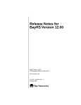
Figure 1 shows a second-generation network topology with a bridge
connecting four LANs or LAN segments, and the same physical topology
with an intelligent switching device (such as one of the Accelar™ family of
routing switches) providing connectivity.
300020-B Rev. 00
7
BayRS Version 12.20 Document Change Notice
Hub
Hub
LAN
Segment 1
LAN Segment 1
Engineering
VLAN
Hub
Hub
LAN
Segment 2
Hub
LAN
Segment 2
Hub
LAN
Segment 3
LAN
Segment 3
Marketing
VLAN
Hub
Hub
LAN
Segment 4
LAN
Segment 4
Bridge
VLAN device
SN0007A
Figure 1.
VLAN Topology
As illustrated in Figure 1, the four VLAN segments can be reconfigured as
two VLANs: the Engineering VLAN, consisting of LAN segments 1 and 2,
and the Marketing VLAN, consisting of LAN segments 3 and 4.
•
A VLAN contains broadcast traffic within software-defined boundaries.
With reference to Figure 1, broadcast traffic within the bridged topology is
propagated across all physical interfaces. For example, a broadcast frame
originated by a workstation on LAN segment 1 is forwarded to LAN
segments 2, 3, and 4. In contrast, within the VLAN topology, a broadcast
frame originated by a workstation on LAN segment 1 is forwarded only to
LAN segment 2. Broadcast traffic is confined with the bounds of the VLAN.
8
300020-B Rev. 00
Configuring Ethernet, FDDI, and Token Ring Services
•
A VLAN provides low-latency, wire-speed communication between VLAN
members.
All members of the Engineering VLAN, for example, communicate at wire
speed whether they are physically connected to LAN segment 1 or 2.
•
A VLAN supports network segmentation or microsegmentation; a VLAN
segment can consist of one or many workstations.
•
A VLAN is a closed bridge group, with boundaries enforced by spanning tree
protocols.
•
Intra-VLAN communication is provided by layer 2 switching.
•
Inter-VLAN communication requires additional layer 3 services. Layer 3
services may be provided by the VLAN device or by an adjacent router.
Intra-VLAN Traffic Flow
Intra-VLAN traffic (where the frame source and the frame destination are both on
the same VLAN) is forwarded at layer 2 by the VLAN device. Forwarding
decisions are based on layer 2 forwarding tables that associate specific MAC/layer
2 addresses with specific device ports.
Inter-VLAN Traffic Flow
Inter-VLAN traffic (where the frame source and the frame destination are not on
the same VLAN) requires layer 3 (routing) services. Certain advanced platforms
(such as the Accelar family of routing switches) can provide these services.
More commonly, however, routing services are provided by an adjacent router, as
shown in Figure 2, where frames originating on the Marketing VLAN and
destined for the Sales VLAN are switched across a dedicated port by the VLAN
device to the attached router. The router, operating at layer 3, redirects the frame
across another dedicated port to the VLAN device, which in turns switches the
frame at layer 2 to the recipient VLAN.
The configuration illustrated in Figure 2 is inefficient for both the router and the
VLAN device, because it requires a dedicated port for each VLAN. In network
topologies that support multiple VLANs, the costs for dedicated ports may be
prohibitive.
300020-B Rev. 00
9
BayRS Version 12.20 Document Change Notice
Engineering
IP VLAN
Marketing
IP VLAN
VLAN
device
Traffic flow
Dedicated VLAN-specific
untagged ports
Sales
IP VLAN
Router
SN0020A
Figure 2.
Connecting VLANs Using a Router
In contrast, Figure 3 depicts a topology in which the same three VLANs share a
common connection to the adjacent router. This common connection is enabled by
a packet encapsulation format specified in IEEE 802.1Q, Draft Standard for
Virtual Bridged Local Area Networks. This packet encapsulation format is
referred to as 802.1Q tagging.
10
300020-B Rev. 00
Configuring Ethernet, FDDI, and Token Ring Services
Engineering
IP VLAN
Marketing
IP VLAN
VLAN
device
Sales
all-protocol VLAN
Traffic flow
Single untagged port serves the
Marketing and Sales VLANs
Router
SN0021A
Figure 3.
Connecting VLANs Using 802.1Q Tagging
802.1Q Tagging
802.1Q tagging enables multiple VLANs to share a common connection to a
router. The router provides layer 3 routing services for the VLAN clients. The
router may provide standard routing services, that is, directing received frames
toward a remote destination; or it may function as a so-called “one-armed” router,
returning frames to the device from which it received them, but forwarding them
to a different logical entity.
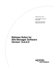
Shared usage of a common physical port (often referred to as a tagged port) is
facilitated by the addition of two 2-byte fields within the standard Ethernet header
(Figure 4).
300020-B Rev. 00
11
BayRS Version 12.20 Document Change Notice
IEEE 802.1Q encapsulation
Ethernet encapsulation
Destination address
(6 octets)
Destination address
(6 octets)
Source address
(6 octets)
Source address
(6 octets)
Tag protocol identifier
(2 octets)
Protocol type
(2 octets)
Tag control information
(2 octets)
Data
(46 to 1496 octets)
Protocol type
(2 octets)
FCS
(4 octets)
Data
(46 to 1496 octets)
Maximum size: 1514 octets
FCS
(4 octets)
Maximum size: 1518 octets
SN0016A
Figure 4.
IEEE 802.1Q Tagging
The IEEE has not yet standardized values for the tag protocol identifier (TPID)
field, leaving vendors to provide their own proprietary values. The Accelar family
of routing switches, for example, writes a value of 8100 (hexadecimal) to this
field.
The tag control information (TCI) field contains a unique value that identifies the
VLAN on which the frame originated. This value is assigned during the
configuration of the layer 2 device.
The addition of the four bytes required for the TPID and TCI fields raises the
possibility of generating frames up to 1518 bytes in length, four bytes larger than
the maximum packet size specified by Ethernet. Consequently, for frames on
which 802.1Q tagging is enabled, BayRS accepts such outsized frames.
12
300020-B Rev. 00
Configuring Ethernet, FDDI, and Token Ring Services
Router Processing of Tagged Frames
802.1Q tagging is supported only on 100BASE-T interfaces that connect the Bay
Networks router to an 802.1Q-compliant switch or routing switch. With 802.1Q
tagging enabled, the physical connection between the router and the adjacent
device supports multiple virtual connections.
The number of connections is equal to the number of virtual connections plus a
default physical connection that provides transit services for other non-VLAN
traffic that may be received from or forwarded to the adjacent device.
Upon receipt of a frame across a virtual connection, a circuit manager strips the
four bytes of 802.1Q header information and directs a now standard Ethernet
frame to a connection-specific routing process. The routing process consults its
forwarding table and, in turn, directs the frame to a circuit manager handling the
next-hop connection. If that connection is a non-tagged, non-virtual connection,
processing is completed as for any other standard Ethernet frame.
However, if the next-hop connection is a tagged, virtual connection, the circuit
manager inserts the four bytes of 802.1Q header information that identify that
VLAN into the standard Ethernet header. After performing the 802.1Q
encapsulation, the circuit manager forwards the frame across the virtual
connection toward the destination VLAN.
Implementation Considerations
Before you configure 802.1Q tagging on a router, note the following
considerations.
300020-B Rev. 00
•
802.1Q tagging is supported only on 100BASE-T interfaces; it is not
supported on other LAN interfaces.
•
802.1Q tagging cannot be used to extend a VLAN across multiple devices.
•
The VLAN type (port-based, protocol-based, address-based, and so on) is
ignored by the router.
13
BayRS Version 12.20 Document Change Notice
Configuring 802.1Q Tagged Circuits
Use Site Manager to configure 802.1Q tagging. This section includes information
about the following topics:
Topic
Page
Adding a Tagged Circuit to an Unconfigured 100BASE-T Interface
-14
Adding a Tagged Circuit to an Existing 100BASE-T Interface
-16
Editing a Tagged Circuit
-17
Disabling a Tagged Circuit
-18
Deleting a Tagged Circuit
-18
Adding a Tagged Circuit to an Unconfigured 100BASE-T Interface
The following procedure describes how to add an 802.1Q tagged circuit to a
previously unconfigured 100BASE-T interface. This procedure assumes that you
are configuring the 802.1Q tagged circuit for IP routing. To enable other routing
protocols on an 802.1Q tagged circuit, see the appropriate guide for that protocol.
Site Manager Procedure
You do this
System responds
1. In the Configuration Manager window,
click on a 100BASE-T connector.
The Add Circuit window opens.
2. Click on OK.
The Select Protocols window opens.
3. Choose VLAN, then click on OK.
The Edit VLAN Interface Parameters
window opens.
4. Click on Add.
The TAG1Q Parameters window opens.
5. Set the following parameters:
• VLAN Name
• Global VLAN Id
Click on Help or see the parameter
descriptions beginning on page -19.
6. Click on OK.
The Edit VLAN Interface Parameters
window opens. Note that 802.1Q tagged
circuits are displayed with a Vn extension.
(continued)
14
300020-B Rev. 00
Configuring Ethernet, FDDI, and Token Ring Services
Site Manager Procedure (continued)
You do this
System responds
7. Select the 802.1Q tagged circuit that you
are adding. Set the Protocol Type (hex)
parameter. Retain the default value for
connection to Bay Networks
802.1Q-enabled devices.
8. Click on Apply and Done.
You return to the Configuration Manager
window.
To add IP routing to the 802.1Q tagged circuit:
9. Choose Circuits.
10. Choose Edit Circuits.
The Circuit List window opens.
11. Select the 802.1Q tagged circuit.
Note that 802.1Q tagged circuits are
displayed with a Vn extension.
12. Click on Edit.
The Circuit Definition window opens.
13. Choose Protocols.
14. Choose Add/Delete.
The Select Protocols window opens.
15. Select IP and click on OK.
The IP Configuration window opens.
16. Enter an IP address and subnet mask and The Circuit Definition window opens.
click on OK.
17. Choose File.
300020-B Rev. 00
18. Choose Exit.
The Circuit List window opens.
19. Click on Done.
You return to the Configuration Manager
window.
15
BayRS Version 12.20 Document Change Notice
Adding a Tagged Circuit to an Existing 100BASE-T Interface
To add an 802.1Q tagged circuit to an existing 100BASE-T interface, complete
the following tasks:
Site Manager Procedure
You do this
System responds
1. In the Configuration Manager window,
click on a 100BASE-T connector.
The Edit Connector window opens.
2. Click on Edit Circuit.
The Circuit Definition window opens.
3. Choose Protocols.
The Protocols menu opens.
4. Choose Add/Delete.
The Select Protocols window opens.
5. Choose VLAN, then click on OK.
The Edit VLAN Interface Parameters
window opens.
6. Click on Add.
The TAG1Q Parameters window opens.
7. Set the following parameters:
• VLAN Name
• Global VLAN Id
Click on Help or see the parameter
descriptions beginning on page -19.
8. Click on OK.
The Edit VLAN Interface Parameters
window opens. Note that 802.1Q tagged
circuits are displayed with a Vn extension.
9. Select the 802.1Q tagged circuit that you
are adding. Set the Protocol Type (hex)
parameter. Retain the default value for
connection to Bay Networks
802.1Q-enabled devices.
10. Click on Apply and Done.
You return to the Configuration Manager
window.
To add IP routing to the 802.1Q tagged circuit:
11. Choose Circuits.
12. Choose Edit Circuits.
The Circuit List window opens.
13. Select the 802.1Q tagged circuit.
Note that 802.1Q tagged circuits are
displayed with a Vn extension.
(continued)
16
300020-B Rev. 00
Configuring Ethernet, FDDI, and Token Ring Services
Site Manager Procedure (continued)
You do this
System responds
14. Click on Edit.
The Circuit Definition window opens.
15. Choose Protocols.
16. Choose Add/Delete.
The Select Protocols window opens.
17. Select IP and click on OK.
The IP Configuration window opens.
18. Enter an IP address and subnet mask and The Circuit Definition window opens.
click on OK.
19. Choose File.
20. Choose Exit.
The Circuit List window opens.
21. Click on Done.
You return to the Configuration Manager
window.
Editing a Tagged Circuit
To edit an 802.1Q tagged circuit, complete the following tasks:
Site Manager Procedure
You do this
System responds
1. In the Configuration Manager window,
choose Protocols.
The Protocols menu opens.
2. Choose VLAN.
The VLAN menu opens.
3. Choose Interfaces.
The Edit VLAN Interface Parameters
window opens.
4. Select the 802.1Q tagged circuit that you
want to edit.
Site Manager displays the current
parameter values for the circuit.
5. Edit the following parameters as required:
• VLAN Name
• Global VLAN Id
• Protocol Type (hex)
Click on Help or see the parameter
descriptions beginning on page -19.
6. Click on Apply and Done.
300020-B Rev. 00
You return to the Configuration Manager
window.
17
BayRS Version 12.20 Document Change Notice
Disabling a Tagged Circuit
To disable an 802.1Q tagged circuit, complete the following tasks:
Site Manager Procedure
You do this
System responds
1. In the Configuration Manager window,
choose Protocols.
The Protocols menu opens.
2. Choose VLAN.
The VLAN menu opens.
3. Choose Interfaces.
The Edit VLAN Interface Parameters
window opens.
4. Select the 802.1Q tagged circuit that you
want to disable.
Site Manager displays the current
parameter values for the circuit.
5. Set the Enable/Disable parameter to
Disable.
6. Click on Apply and Done.
You return to the Configuration Manager
window.
Deleting a Tagged Circuit
To delete an 802.1Q tagged circuit, complete the following tasks:
Site Manager Procedure
18
You do this
System responds
1. In the Configuration Manager window,
choose Protocols.
The Protocols menu opens.
2. Choose VLAN.
The VLAN menu opens.
3. Choose Interfaces.
The Edit VLAN Interface Parameters
window opens.
4. Select the 802.1Q tagged circuit that you
want to delete.
Site Manager displays the current
parameter values for the circuit.
5. Click on Delete and Done.
You return to the Configuration Manager
window.
300020-B Rev. 00
Configuring Ethernet, FDDI, and Token Ring Services
802.1Q Parameters
The Edit VLAN Interface Parameters window contains the parameters for all
802.1Q tagged circuits on the router. The parameter descriptions follow:
Parameter: Enable/Disable
Path:
Default:
Options:
Function:
Instructions:
Configuration Manager > Protocols > VLAN > Interfaces
Enable
Enable | Disable
Enables or disables the 802.1Q tagged circuit.
Set to Disable to disable a previously configured 802.1Q tagged circuit. Set to
Enable to enable a disabled 802.1Q tagged circuit.
MIB Object ID: 1.3.1.6.1.4.1.18.3.5.1.12.6.1.1.1.2
Parameter: VLAN Name
Path:
Default:
Options:
Function:
Configuration Manager > Protocols > VLAN > Interfaces
None
Any character string
Provides a mnemonic to associate with the VLAN. This string is not used by
BayRS.
Instructions: Enter a name for the VLAN.
MIB Object ID: 1.3.1.6.1.4.1.18.3.5.1.12.6.1.1.1.3
Parameter: Global VLAN Id
Path:
Default:
Options:
Function:
Instructions:
Configuration Manager > Protocols > VLAN > Interfaces
None
Any integer value from 1 to 4095
Provides a unique identifier for the VLAN within the layer 2/layer 3 topology
Enter the unique VLAN numeric identifier that was assigned to the VLAN
when it was initially configured on the adjacent layer 2 device. This value must
match the one assigned during the initial VLAN configuration.
MIB Object ID: 1.3.1.6.1.4.1.18.3.5.1.12.6.1.1.1.5
300020-B Rev. 00
19
BayRS Version 12.20 Document Change Notice
Parameter: Protocol Type (hex)
Path:
Default:
Options:
Function:
Configuration Manager > Protocols > VLAN > Interfaces
33024 (8100 hexadecimal)
Any integer value
Specifies the contents of the TPID field in 802.1Q encapsulated frames
originated by this VLAN.
Instructions: Enter (in decimal notation) the TPID value that was assigned to the VLAN
when it was initially configured on the adjacent layer 2 device. This value must
match the one assigned during the initial VLAN configuration.
MIB Object ID: 1.3.1.6.1.4.1.18.3.5.1.12.6.1.1.1.8
20
300020-B Rev. 00
Configuring IP Utilities
Configuring IP Utilities
The following sections are amendments to Configuring IP Utilities:
Section
Page
DNS Overview
-21
Creating the DNS Client
-22
Customizing the DNS Client
-23
Disabling DNS
-28
Deleting DNS
-29
DNS Global Parameters
-29
DNS Server Record Parameters
-33
DNS Overview
The Domain Name System (DNS) is a distributed database system, with DNS
clients requesting host name/address resolution information from various DNS
servers. DNS is used with numerous types of networking applications and
protocols.
Specifically, DNS provides a directory service that allows client devices to
retrieve information from a server-based database. For the Internet, DNS enables
a device to obtain the IP address of a host based on the host’s domain name.
The Bay Networks router functions as a DNS client.
300020-B Rev. 00
21
BayRS Version 12.20 Document Change Notice
Creating the DNS Client
To create the DNS client, first configure an IP interface. Then create and enable
the DNS client by completing the following tasks:
Site Manager Procedure
You do this
System responds
1. In the Configuration Manager window,
choose Protocols.
The Protocols menu opens.
2. Choose Global Protocols.
The Global Protocols menu opens.
3. Choose DNS.
The DNS menu opens.
4. Choose Create DNS.
The DNS Configuration window opens.
5. Click on OK.
You return to the Configuration Manager
window.
After you create and enable the DNS client, you must specify at least one DNS
server. You can specify up to a maximum of three DNS servers. To specify a DNS
server, complete the following tasks:
Site Manager Procedure
You do this
System responds
1. In the Configuration Manager window,
choose Protocols.
The Protocols menu opens.
2. Choose Global Protocols.
The Global Protocols menu opens.
3. Choose DNS.
The DNS menu opens.
4. Choose DNS Servers.
The DNS Server List window opens.
5. Click on Add.
The DNS Server Record window opens.
6. Set the following parameters:
• Index
• IP Address
• Port Number
Click on Help or see the parameter
descriptions beginning on page -33.
(continued)
22
300020-B Rev. 00
Configuring IP Utilities
Site Manager Procedure (continued)
You do this
System responds
7. Click on OK.
The DNS Server List window reopens; it
now lists the index value and the IP
address of the server you configured.
8. Click on Done.
You return to the Configuration Manager
window.
Customizing the DNS Client
When you create the DNS client, default values are in effect for all parameters.
You may want to change these values, depending on the requirements of your
network.
This section provides information about how to customize the DNS client
configuration. It includes information about the following topics:
300020-B Rev. 00
Topic
Page
Modifying the DNS Client Configuration
-24
Disabling the Recursion Bit
-24
Modifying How the DNS Client Handles Server Responses
-25
Modifying the DNS Server List
-26
23
BayRS Version 12.20 Document Change Notice
Modifying the DNS Client Configuration
You can modify how the router makes requests to the DNS server, for example,
how often requests are repeated and how long it waits between requests.
To modify how the router sends DNS requests, complete the following tasks:
Site Manager Procedure
You do this
System responds
1. In the Configuration Manager window,
choose Protocols.
The Protocols menu opens.
2. Choose Global Protocols.
The Global Protocols menu opens.
3. Choose DNS.
The DNS menu opens.
4. Choose Global.
The Edit DNS Global Parameters window
opens.
5. Edit any of the following parameters:
• Time Out
• Max Retransmission
• Max Outstanding Query
• IP Type of Service
• Domain Name
• Use Default Domain Name
Click on Help or see the parameter
descriptions beginning on page -29.
6. Click on OK.
You return to the Configuration Manager
window.
Disabling the Recursion Bit
If the first DNS server that the router contacts does not have the information
requested, you can instruct that server to contact another server that can respond
by setting a recursion bit in the DNS information header packet.
The recursion bit is enabled by default. If you do not want to contact more than
one server, you must disable the recursion bit.
24
300020-B Rev. 00
Configuring IP Utilities
To disable the recursion bit, complete the following tasks:
Site Manager Procedure
You do this
System responds
1. In the Configuration Manager window,
choose Protocols.
The Protocols menu opens.
2. Choose Global Protocols.
The Global Protocols menu opens.
3. Choose DNS.
The DNS menu opens.
4. Choose Global.
The Edit DNS Global Parameters window
opens.
5. Set the Recursion parameter to Disable.
Click on Help or see the parameter
description on page -32.
6. Click on OK.
You return to the Configuration Manager
window.
Modifying How the DNS Client Handles Server Responses
To specify whether the router accepts the DNS server’s response when it contains
a truncation bit or whether the router accepts data from only the authorized DNS
server, complete the following tasks:
Site Manager Procedure
You do this
System responds
1. In the Configuration Manager window,
choose Protocols.
The Protocols menu opens.
2. Choose Global Protocols.
The Global Protocols menu opens.
3. Choose DNS.
The DNS menu opens.
4. Choose Global.
The Edit DNS Global Parameters window
opens.
(continued)
300020-B Rev. 00
25
BayRS Version 12.20 Document Change Notice
Site Manager Procedure (continued)
You do this
System responds
5. Edit one or both of the following
parameters:
• Ignore Truncation Error
• Use Auth Answer Only
Click on Help or see the parameter
descriptions on page -32.
6. Click on OK.
You return to the Configuration Manager
window.
Modifying the DNS Server List
The DNS server list contains the DNS servers (up to a maximum of three) that the
DNS client can query. You can add and delete entries in the DNS server list.
Displaying the DNS Server List
To view the list of DNS servers to which the router can connect, complete the
following tasks:
Site Manager Procedure
26
You do this
System responds
1. In the Configuration Manager window,
choose Protocols.
The Protocols menu opens.
2. Choose Global Protocols.
The Global Protocols menu opens.
3. Choose DNS.
The DNS menu opens.
4. Choose DNS Servers.
The DNS Server List window opens. This
window lists all configured DNS servers.
5. Select a server from the list.
The DNS Server List window displays the
IP address and DNS port for the selected
server.
6. Click on Done.
You return to the Configuration Manager
window.
300020-B Rev. 00
Configuring IP Utilities
Adding Entries to the DNS Server List
To add a new entry (up to a maximum of three) to the DNS server list, complete
the following tasks:
Site Manager Procedure
You do this
System responds
1. In the Configuration Manager window,
choose Protocols.
The Protocols menu opens.
2. Choose Global Protocols.
The Global Protocols menu opens.
3. Choose DNS.
The DNS menu opens.
4. Choose DNS Servers
The DNS Server List window opens. This
window lists all configured DNS servers.
5. Click on Add.
The DNS Server Record window opens.
6. Set the following parameters:
• Index
• IP Address
• Port Number
Click on Help or see the parameter
descriptions on page -33.
7. Click on OK.
The DNS Server List window reopens.
8. Click on Apply and Done.
You return to the Configuration Manager
window.
Deleting Entries from the DNS Server List
To delete an entry from the DNS server list, complete the following tasks:
Site Manager Procedure
You do this
System responds
1. In the Configuration Manager window,
choose Protocols.
The Protocols menu opens.
2. Choose Global Protocols.
The Global Protocols menu opens.
3. Choose DNS.
The DNS menu opens.
(continued)
300020-B Rev. 00
27
BayRS Version 12.20 Document Change Notice
Site Manager Procedure (continued)
You do this
System responds
4. Choose DNS Servers.
The DNS Server List window opens. This
window lists all configured DNS servers.
5. Select the server that you want to delete.
Site Manager highlights the entry.
6. Click on Delete.
Site Manager removes the entry.
7. Click on OK.
The DNS Server List window reopens.
8. Click on Apply and Done.
You return to the Configuration Manager
window.
Disabling DNS
To disable DNS client services from all circuits on the router, complete the
following tasks:
Site Manager Procedure
28
You do this
System responds
1. In the Configuration Manager window,
choose Protocols.
The Protocols menu opens.
2. Choose Global Protocols.
The Global Protocols menu opens.
3. Choose DNS.
The DNS menu opens.
4. Choose Global.
The Edit DNS Global Parameters window
opens.
5. Set the Enable parameter to Disable.
Click on Help or see the parameter
description on page -29.
Site Manager disables DNS on the router.
6. Click on OK.
You return to the Configuration Manager
window.
300020-B Rev. 00
Configuring IP Utilities
Deleting DNS
To delete DNS client services from the router, complete the following tasks:
Site Manager Procedure
You do this
System responds
1. In the Configuration Manager window,
choose Protocols.
The Protocols menu opens.
2. Choose Global Protocols.
The Global Protocols menu opens.
3. Choose DNS.
The DNS menu opens.
4. Choose Delete DNS.
A message window prompts:
Do you REALLY want to delete
DNS?
5. Click on OK.
You return to the Configuration Manager
window.
DNS Global Parameters
The Edit DNS Global Parameters window contains the global DNS parameters for
the DNS client on the router. The parameter descriptions follow.
Parameter: Enable
Path:
Default:
Options:
Function:
Instructions:
Configuration Manager > Protocols > Global Protocols > DNS > Global
Enable
Enable | Disable
Enables or disables DNS on the router.
Accept the default, Enable, to enable DNS client services on this router. To
temporarily disable DNS, set this parameter to Disable.
MIB Object ID: 1.3.6.1.4.1.18.3.5.3.19.1.2
300020-B Rev. 00
29
BayRS Version 12.20 Document Change Notice
Parameter: Time Out
Path:
Default:
Options:
Function:
Configuration Manager > Protocols > Global Protocols > DNS > Global
5
1 to 60 seconds
Specifies, in seconds, the amount of time the router waits before it retransmits a
request to the DNS server.
Instructions: If you have a large network, set this value higher than the default, so that the
router will not time out before it receives a response from the DNS server.
Otherwise, accept the default.
MIB Object ID: 1.3.6.1.4.1.18.3.5.3.19.1.3
Parameter: Max Retransmission
Path:
Default:
Options:
Function:
Configuration Manager > Protocols > Global Protocols > DNS > Global
3
0 to 15
Specifies the maximum number of times that the router can retransmit a request
to the DNS server before it records an error.
Instructions: Accept the default, or enter a value from 0 to 15. Entering a high value may
delay router response time when errors occur.
MIB Object ID: 1.3.6.1.4.1.18.3.5.3.19.1.4
Parameter: Max Outstanding Query
Path:
Default:
Options:
Function:
Configuration Manager > Protocols > Global Protocols > DNS > Global
20
1 to 100
Specifies the maximum number of outstanding queries to the server that the
router allows.
Instructions: Accept the default, or enter a value from 1 to 100. If you select a high value, be
sure that the router has enough memory to accommodate the number of
outstanding queries that you specify.
MIB Object ID: 1.3.6.1.4.1.18.3.5.3.19.1.5
30
300020-B Rev. 00
Configuring IP Utilities
Parameter: IP Type of Service
Path:
Default:
Options:
Function:
Configuration Manager > Protocols > Global Protocols > DNS > Global
Low Delay
Normal | Low Delay
Specifies the type of service set in the IP datagram. The type of service specifies
to the transport layer (UDP) how the router handles DNS packets.
Instructions: Bay Networks recommends Low Delay for DNS packet transfers, because a
Low Delay setting specifies a high priority for the packets.
MIB Object ID: 1.3.6.1.4.1.18.3.5.3.19.1.6
Parameter: Domain Name
Path: Configuration Manager > Protocols > Global Protocols > DNS > Global
Default: None
Options: Any combination of up to 255 alphanumeric characters that specifies a network
domain, for example, baynetworks.com.
Function: Specifies the default domain name that the router uses when trying to reach a
DNS server. You can use this domain name when issuing a ping command to
verify the connection to a DNS server. For Version 12.20, this parameter is valid
only for use with the Technician Interface.
For example, if you want to check the connection from router A to remote Bay
Networks router B, you can set this parameter to baynetworks.com. When you
enter the command ping router, router A, the DNS client, adds
baynetworks.com to the command, making the actual command
ping router.baynetworks.com. The DNS server translates the name to an IP
address.
Instructions: Enter the default domain name.
MIB Object ID: 1.3.6.1.4.1.18.3.5.3.19.1.7
300020-B Rev. 00
31
BayRS Version 12.20 Document Change Notice
Parameter: Recursion
Path:
Default:
Options:
Function:
Configuration Manager > Protocols > Global Protocols > DNS > Global
Enable
Enable | Disable
Sets the recursion bit in the DNS packet header so that if the first server that the
router contacts does not have the required information, that server finds another
server that can respond to the request.
Instructions: Bay Networks recommends that you accept the default, Enable, to implement
recursion for resolving requests to a DNS server.
MIB Object ID: 1.3.6.1.4.1.18.3.5.3.19.1.8
Parameter: Ignore Truncation Error
Path:
Default:
Options:
Function:
Configuration Manager > Protocols > Global Protocols > DNS > Global
Enable
Enable | Disable
Specifies whether the router should reject DNS server responses that contain the
truncation bit in the DNS header. Typically the information that the router uses
is in the first few bytes of the response messages, so it can ignore the rest of the
message.
Instructions: Accept the default, Enable, to ignore the error messages. To accept truncation
error messages, set this parameter to Disable.
MIB Object ID: 1.3.6.1.4.1.18.3.5.3.19.1.9
Parameter: Use Auth Answer Only
Path:
Default:
Options:
Function:
Instructions:
Configuration Manager > Protocols > Global Protocols > DNS > Global
Disable
Enable | Disable
Specifies whether the router should accept data only from the authorized server.
Select Enable to accept data only from an authorized server. Select Disable to
accept data from any server.
MIB Object ID: 1.3.6.1.4.1.18.3.5.3.19.1.10
32
300020-B Rev. 00
Configuring IP Utilities
Parameter: Use Default Domain Name
Path:
Default:
Options:
Function:
Configuration Manager > Protocols > Global Protocols > DNS > Global
Enable
Enable | Disable
If you entered a value for the Domain Name parameter, this parameter instructs
the router to use that name when sending requests to a DNS server.
Instructions: Accept the default, Enable, to use the default domain name. Otherwise, select
Disable.
MIB Object ID: 1.3.6.1.4.1.18.3.5.3.19.1.11
DNS Server Record Parameters
The DNS Server Record window contains the parameters that specify the
“approved” DNS servers for the router’s DNS client. The parameter descriptions
follow.
Parameter: Index
Path: Configuration Manager > Protocols > Global Protocols > DNS > DNS Servers
> Add
Default: None
Options: 1 to 3
Function: Specifies the order in which the router contacts the DNS server. For example,
the router first contacts a server with an index of 1. If that server is not
operating, the router then contacts a server with an index of 2.
Instructions: Determine the order in which you want the router to contact a particular server
and assign the appropriate index value to that server.
MIB Object ID: 1.3.6.1.4.1.18.3.5.3.19.2.1.2
300020-B Rev. 00
33
BayRS Version 12.20 Document Change Notice
Parameter: IP Address
Path: Configuration Manager > Protocols > Global Protocols > DNS > DNS Servers
> Add
Default: 0.0.0.0
Options: Any valid IP address
Function: Specifies the IP address of the DNS server that responds to DNS client requests.
Instructions: Enter a 32-bit IP address.
MIB Object ID: 1.3.6.1.4.1.18.3.5.3.19.2.1.3
Parameter: Port Number
Path: Configuration Manager > Protocols > Global Protocols > DNS > DNS Servers
> Add
Default: 53
Options: 1 to 46000
Function: Specifies the UDP port on the DNS server to which the router should connect.
Instructions: In most cases, accept the default. Only in special situations should you specify
another UDP port number.
MIB Object ID: 1.3.6.1.4.1.18.3.5.3.19.2.1.4
34
300020-B Rev. 00
Configuring OSI Services
Configuring OSI Services
The following sections are amendments to Configuring OSI Services.
Section
Page
Configuring OSI over ATM
-35
Configuring Manual Area Addresses
-36
Configuring OSI and TARP
-38
Configuring OSI over ATM
To configure OSI to run over ATM, complete the following tasks:
Site Manager Procedure
You do this
System responds
1. In the Configuration Manager window,
click on an ATM link module interface
(ATM1).
The Add Circuit window opens.
2. Click on OK.
The Initial ATM Signaling Config window
opens.
3. Edit any parameters you need to change.
Click on Help for more information about
any field. For OSI over ATM, Protocol
Standard can be either UNI_V30 or
UNI_V31.
4. Click on OK.
The Edit ATM Connector window opens.
5. Click on Service Attributes.
The ATM Service Records List window
opens.
6. Click on Add.
The ATM Service Record Parameters
window opens.
7. Set the Data Encapsulation Type
parameter to LLC/SNAP or NLPID.
8. Press the Enter or Tab key to advance to
the Virtual Connection Type parameter.
9. Set the Virtual Connection Type
parameter to PVC.
(continued)
300020-B Rev. 00
35
BayRS Version 12.20 Document Change Notice
Site Manager Procedure (continued)
You do this
System responds
10. Click on OK.
The Select Protocols window opens.
11. Click on OSI, then click on OK.
The OSI Configuration window opens.
12. Set the Router ID parameter. Click on
Help for more information.
13. Click on OK.
Site Manager asks if you want to edit the
OSI interface details.
14. Click on OK to edit OSI interface
parameters or Cancel to accept the
default values.
The ATM Virtual Channel Link window
opens.
15. Click on Add.
The ATM Virtual Channel Link
Parameters window opens.
16. Set the VPI Number parameter. Click on
Help for more information.
17. Set the VCI Number parameter. Click on
Help for more information.
18. Click on OK.
You return to the ATM Virtual Channel
Link window.
19. Click on Done.
You return to the ATM Service Records
List window.
20. Click on Done.
You return to the Edit ATM Connector
window.
21. Click on Done.
You return to the Configuration Manager
window.
Configuring Manual Area Addresses
Manual area addresses are synonymous area addresses configured on the
same intermediate system. You may want to configure manual area addresses
when more than one addressing authority can assign addresses to the routing
domain, or to allow a routing domain to be reconfigured during operation.
Note: The OSI Area Address Alias 1 and Area Address Alias 2 parameters,
used in previous releases to configure manual area addresses, no longer exist.
36
300020-B Rev. 00
Configuring OSI Services
To configure manual area addresses for OSI, complete the following tasks:
Site Manager Procedure
You do this
System responds
1. In the Configuration Manager window,
choose Protocols.
The Protocols menu opens.
2. Choose OSI.
The OSI menu opens.
3. Choose Manual Area Addresses.
The OSI Area Address Configuration
window opens.
4. Click on Add.
The OSI Area Address Configuration Add
window opens.
5. Enter an area address. Click on Help or
see the parameter description below for
more information.
6. Click on OK.
7. To add more area addresses, repeat steps
4 through 6.
8. Click on Done.
Site Manager adds the addresses you
specified.
Parameter: Area Address
Path:
Default:
Options:
Function:
Configuration Manager > Protocols > OSI > Manual Area Addresses
None
Any valid OSI address in hexadecimal notation from 3 to 13 bytes long
Specifies a synonymous area address configured on the same intermediate
system.
Instructions: Enter an area address in hexadecimal notation.
MIB Object ID: 1.3.6.1.4.1.18.3.5.6.1.16
300020-B Rev. 00
37
BayRS Version 12.20 Document Change Notice
Configuring OSI and TARP
OSI uses the TID Address Resolution Protocol (TARP) to map OSI network
service access point (NSAP) Level 3 addresses to target identifier (TID)
addresses. It is similar to the DNS protocol that IP uses, where names are
converted to IP addresses.
A TID is a name that applies to an entire router. It can be any text string, up to 40
characters long, and is similar to a UNIX host name. OSI addresses also apply to
an entire router. An OSI NSAP address consists of the domain address, area
address, the router ID, and a value called the N selector, which is always 00. It can
be up to 13 bytes long.
TARP locates either the OSI NSAP address of a particular TID address or the TID
address of a particular OSI NSAP address.
How TARP Works
TARP resolves the NSAP-to-TID mapping by flooding requests that network
management stations originate throughout the OSI domain. When a request
reaches the network entity that owns the requested TID or NSAP, that entity sends
a response that contains its NSAP and TID back to the originator. When the
management station obtains the address it requested, it can proceed with its
operation, such as polling the device for alarms.
The router’s role is to propagate the requests throughout the network, forwarding
them to Level 1 or Level 2 adjacencies, as appropriate.
TARP Packet Types
TARP has five types of packets (Table 2).
Table 2.
TARP Packet Types
Packet Type
Function
Type 1
Request for the OSI NSAP address that maps to the TID address that
the request packet supplies. Type 1 requests are only flooded within
the originating network entity’s routing area (Level 1 adjacencies).
Type 2
Same request as Type 1, but the requests are flooded throughout the
OSI domain (both Level 1 and Level 2 adjacencies).
(continued)
38
300020-B Rev. 00
Configuring OSI Services
Table 2.
TARP Packet Types (continued)
Packet Type
Function
Type 3
Response to either a Type 1, Type 2, or Type 5 request. This response
is sent directly to the originator of the request.
Type 4
Notification of a change made to either the TID or NSAP address of a
network entity. Type 4 packets are flooded throughout the OSI domain.
Type 5
Request for the TID that maps to the OSI NSAP address included in
the request packet. Because the destination NSAP is known, the
request is sent directly to the network entity.
TARP Packet Fields
Each TARP packet includes the following fields (Table 3):
Table 3.
300020-B Rev. 00
TARP Packet Fields
Name
Length
in Bytes Description
tar_lif
2
TARP lifetime (hops). If the network entity receives a TARP
packet with a tar_lif field equal to 0, it discards the packet.
Before forwarding a TARP packet, a receiving device
decrements this field by 1. If the field then has a value of 0, it
can drop the packet rather than forwarding it to a recipient that
will drop it.
tar_seq
2
TARP sequence number. The originating network entity
assigns a sequence number to each packet it originates. For
each new packet, the sequence number increments by 1.
tar_pro
1
Protocol Address Type. This field must have a value of FE.
tar_tcd
1
TARP type code. The type of TARP packet.
tar_tln
1
Target TID length. The number of octets present in the tar_tor
field.
tar_oln
1
Originator TID length. The number of octets present in the
tar_tor field.
tar_pln
1
NSAP length. The number of octets in the tar_por field.
tar_ttg
N
Target TID.
tar_tor
N
Originator TID.
tar_por
N
NSAP of originator.
39
BayRS Version 12.20 Document Change Notice
Originating TARP Requests
For the router to act as a TARP client, it must be able to originate all five types of
packets. The router maintains a data cache that contains the results of TARP
requests it has made and generates a Type 3 response to Type 1 or Type 5 packets.
The router also generates TARP requests via Technician Interface commands.
Before they send out a TARP request, the TARP entities check the TARP data
network’s caches for a mapping and send out the request only if they do not find
one. Because the main purpose of the Bay Networks implementation of TARP is
to forward TARP packets, the router originates TARP requests for debugging
purposes only, and so sends out requests whether or not there is a match in the
data cache.
Finding an NSAP
If you use the -f option with the Technician Interface tarp pkt command on the
router, you can learn the NSAP of a particular TID. The router sends a Type 1
packet to all Level 1 OSI adjacencies, and the T1 timer is set. If T1 expires before
the router receives a response, it sends a Type 2 request to all Level 1 and Level 2
OSI adjacencies, and the T2 timer is set. If T2 expires before the router receives a
response, the T4 timer is started, and an error recovery procedure begins. When
the T4 timer expires, the router generates a second Type 2 request, and the T2
timer starts again. If T2 expires before the router receives a response, the router
reports back to the application that the TID could not be resolved.
Finding a TID
To learn the TID of a particular NSAP, the router sends a Type 5 packet. Because
it knows the destination NSAP, it does not flood the request out all adjacencies. It
sends the Type 5 request directly to that NSAP, and starts the T3 timer. If the T3
timer expires before the router receives a response, the router reports back to the
application that the NSAP could not be resolved.
40
300020-B Rev. 00
Configuring OSI Services
Receiving TARP Requests
After OSI processes an inbound OSI packet and determines that it is a TARP
packet, the TARP software examines the packet. If the tar_lif field has a value of
0, it discards the packet. If the tar_pro field has a value other than FE, it discards
the packet. It performs the loop detection procedure on the tar_seq field. If the
packet passes all of these checks, TARP then checks to see if the packet is for
itself as follows:
300020-B Rev. 00
•
If the tar_tcd field has a value of 1 or 2 and the tar_ttg field is the router’s
TID, the request is for this router. It responds with a Type 3 packet.
•
If the tar_tcd field has a value of 3, it is either for this router or it could be a
Type 3 response packet to another router. The router checks to see whether it
has any outstanding requests of Type 1, 2, or 5 that match this response. If so,
it removes the request from the queue of outstanding requests that it has sent
and creates an entry in the TARP data cache for the NSAP/TID pair the
response describes. If not, it drops the packet.
•
If the tar_tcd field has a value of 4, the router processes and floods it to its
adjacencies. It checks the TARP data cache for an entry that matches the TID
in the tar_tor field. If found, it updates the TID/NSAP pair in the data cache
with the new information. Then it floods the Type 4 packet to all of its Level 1
and Level 2 adjacencies, except the one that sent the packet, and resets the
sequence number of this packet.
•
If the tar_tcd field has a value of 5, it is a request for this router’s TID. The
router responds with a Type 3 packet or by forwarding a Type 5 packet to
another router.
•
If none of the above cases is true, the router forwards the packet to its
appropriate adjacencies.
41
BayRS Version 12.20 Document Change Notice
Loop Detection
To prevent TARP storms and recursive loops in a looped topology, TARP
maintains a loop detection buffer that keeps a record of the last sequence number
received from a particular NSAP. It checks each TARP PDU that it receives
against any corresponding entry in the loop detection buffer.
If it finds no match:
•
It processes the packet and adds a new entry to the loop detection buffer.
•
It checks the tar_seq field. If the value is 0, it starts a timer set to the value you
configure for the TARP LDB timer. When this timer expires, the entry is
removed.
If there is a match, TARP compares the tar_seq value in the received packet with
the value in the LDB entry.
•
If the packet’s tar_seq value is nonzero and is lower than the value in the
buffer, it discards the packet.
•
If the packet’s tar_seq value is greater than the value in the buffer, TARP
processes the packet and assigns this tar_seq value to the buffer.
•
If the packet’s tar_seq value is 0 and the TARP LDB timer is running, TARP
discards the packet. If the timer is not running, the tar_seq remains 0 and the
TARP LDB timer is started.
Loop Detection Buffer Size
You can configure the maximum number of entries for the loop detection buffer.
When a loop detection buffer that contains the maximum number of entries
receives a new entry, TARP removes the oldest entry.
Loop Detection Timer
Each tar_seq field with a value of 0 has an associated timer, the TARP LDB timer,
that you can configure. When this timer expires, TARP removes the entry from
the buffer.
42
300020-B Rev. 00
Configuring OSI Services
Flush Timer
The loop detection buffer also has a flush timer. When it expires, TARP empties
the entire buffer. You can configure this timer to any value from 0 to 1440
minutes. The default value is 5 minutes.
Configuring TARP
You can use Site Manager to configure TARP parameters. However, to originate
TARP requests and to view the contents of the TARP data caches and the L2 data
cache, you must use the Technician Interface.
To configure TARP, you need to provide a target ID (TID) for the first circuit you
configure. All other parameters have default values, which you can edit to suit the
requirements of your network.
Site Manager Procedure
You do this
System responds
1. In the Configuration Manager window,
choose a link or net module.
The Add Circuit window opens.
2. Click on OK.
The Select Protocols window opens.
3. Choose OSI and TARP, then click on OK.
The OSI Configuration window opens.
4. Set the Router ID parameter. Click on
Help or see the parameter description on
page -48.
5. Click on OK.
A dialog box prompts: “Do you want to
edit the OSI Interface details?”
6. Click on Cancel.
The TARP Parameters window opens.
7. Set the Target Identifier parameter. Click
on Help or see the parameter description
on page -49.
8. Click on OK.
The Edit OSI Interface window opens.
9. Accept the defaults, or edit the parameters You return to the Configuration Manager
as your network requires. When you are
window.
finished, click on OK.
300020-B Rev. 00
43
BayRS Version 12.20 Document Change Notice
Editing TARP Global Parameters
To edit TARP global parameters, complete the following tasks:
Site Manager Procedure
You do this
System responds
1. In the Configuration Manager window,
choose Protocols > OSI > Tarp >
Global.
The Edit TARP Global Parameters
window opens.
2. Edit one or more of the following
parameters:
• Enable
• Target Identifier
• Tarp Originate
• Pkt Lifetime
• Start Sequence Number
• Tarp Data Cache
• Tarp L2 Data Cache
• Tarp T1 Timer
• Tarp T2 Timer
• Tarp T3 Timer
Click on Help or see the parameter
descriptions beginning on page -48.
3. When you are finished, click on OK.
44
You return to the Configuration Manager
window.
300020-B Rev. 00
Configuring OSI Services
Editing TARP Circuit Parameters
To edit TARP circuit parameters, complete the following tasks:
Site Manager Procedure
You do this
System responds
1. In the Configuration Manager window,
choose Protocols > OSI > Tarp >
Circuits.
The TARP Interface Lists window opens.
2. Edit any of the following parameters:
• Enable
• Circuit Propagate Pkts
• Circuit Originate Pkts
Click on Help or see the parameter
descriptions page -52.
3. Click on Done.
You return to the Configuration Manager
window.
Adding or Deleting TARP Static Adjacencies
To add a TARP static adjacency, complete the following tasks:
Site Manager Procedure
You do this
System responds
1. In the Configuration Manager window,
choose Protocols > OSI > Tarp >
ADJ TARP.
The TARP Static Adjacencies window
opens.
2. Click on Add.
The Static Adjacencies Configuration
window opens.
3. Set the Static Adjacent NSAP Address
parameter. Include a 00 NSEL value at the
end of the NSAP address. Click on Help or
see the parameter description on
page -53.
300020-B Rev. 00
4. Click on OK.
The TARP Static Adjacencies window
opens.
5. Click on Done.
You return to the Configuration Manager
window.
45
BayRS Version 12.20 Document Change Notice
To delete a TARP static adjacency, complete the following tasks:
Site Manager Procedure
You do this
System responds
1. In the Configuration Manager window,
choose Protocols > OSI > Tarp >
ADJ TARP.
The TARP Static Adjacencies window
opens.
2. Select a static adjacency address, then
click on Delete.
The Static Adjacencies address is no
longer visible.
3. Click on Done.
You return to the Configuration Manager
window.
Configuring TARP to Ignore a Static Adjacency
To configure TARP to ignore a defined static adjacency, complete the following
tasks:
Site Manager Procedure
You do this
System responds
1. In the Configuration Manager window,
choose Protocols > OSI > Tarp >
ADJ Ignore.
The TARP Ignore Adjacencies window
opens.
2. Click on Add.
The Ignore Adjacencies Configuration
window opens.
3. Set the Ignore Adjacent NSAP Address
parameter. Click on Help or see the
parameter description on page -54.
46
4. Click on OK.
You return to the TARP Ignore
Adjacencies window.
5. Click on Done.
You return to the Configuration Manager
window.
300020-B Rev. 00
Configuring OSI Services
To delete a TARP Ignore Adjacency setting, complete the following tasks:
Site Manager Procedure
You do this
System responds
1. In the Configuration Manager window,
choose Protocols > OSI > Tarp >
ADJ Ignore.
The TARP Ignore Adjacencies window
opens.
2. Select an ignore adjacency address, then
click on Delete.
The selected address is no longer visible.
3. Click on Done.
You return to the Configuration Manager
window.
To enable or disable a TARP Ignore Adjacency setting, complete the following
tasks:
Site Manager Procedure
You do this
System responds
1. In the Configuration Manager window,
choose Protocols > OSI > Tarp >
ADJ Ignore.
The TARP Ignore Adjacencies window
opens.
2. Select an ignore adjacency NSAP
address, then click on Values.
The Values Selection window opens.
3. Set the Enable parameter. Click on Help
or see the parameter description on
page -53.
300020-B Rev. 00
4. Click on OK.
The TARP Ignore Adjacencies window
opens.
5. Click on Done.
You return to the Configuration Manager
window.
47
BayRS Version 12.20 Document Change Notice
TARP Parameter Descriptions
This section describes TARP parameters. This is the same information you receive
using Site Manager online Help.
TARP Global Parameters
This section describes TARP global parameters.
Parameter: Router ID
Path:
Default:
Options:
Function:
Configuration Manager > Protocols > OSI > Global
The router ID set when you initially enable OSI services
Any valid 6-byte system ID
Identifies the router within its local area. The system ID is the ID portion of the
router’s NSAP address.
Instructions: You specify the router ID only the first time you configure an OSI interface. Site
Manager uses this router ID for any additional interfaces you configure. Enter a
new 6-byte system ID in hexadecimal format. If the ID is not 6 bytes, add
leading zeros. Every router in a domain must have a unique system ID; using a
router’s MAC address for the system ID meets this requirement.
MIB Object ID: 1.3.6.1.4.1.18.3.5.6.1.6
Parameter: Enable
Path:
Default:
Options:
Function:
Instructions:
Configuration Manager > Protocols > OSI > Tarp > Global
Enable
Enable | Disable
Enables or disables TARP on this interface.
If you want to use TARP on the interface, accept the default. Otherwise, choose
Disable.
MIB Object ID: 1.3.6.1.4.1.18.3.5.6.14.2
48
300020-B Rev. 00
Configuring OSI Services
Parameter: Target Identifier
Path:
Default:
Options:
Function:
Configuration Manager > Protocols > OSI > Tarp > Global
None
Any text string from 4 to 40 characters (spaces not allowed)
Identifies the router. This is the value that OSI TARP maps to the NSAP
address.
Instructions: Enter the name that identifies this router.
MIB Object ID: 1.3.6.1.4.1.18.3.5.6.14.4
Parameter: Tarp Originate
Path:
Default:
Options:
Function:
Configuration Manager > Protocols > OSI > Tarp > Global
Enable
Enable | Disable
Specifies whether the router can originate TARP packets for this interface. The
only reason for the router to originate TARP packets is for debugging purposes.
A router can forward TARP packets even if it cannot originate TARP packets.
Instructions: If you want the router to originate TARP packets, accept the default. Otherwise,
choose Disable.
MIB Object ID: 1.3.6.1.4.1.18.3.5.6.14.5
Parameter: Pkt Lifetime
Path:
Default:
Options:
Function:
Configuration Manager > Protocols > OSI > Tarp > Global
25
1 to 100
Specifies the maximum number of hops a TARP packet that this router
originates can make.
Instructions: Choose a value within the valid range, or accept the default value.
MIB Object ID: 1.3.6.1.4.1.18.3.5.6.14.6
300020-B Rev. 00
49
BayRS Version 12.20 Document Change Notice
Parameter: Start Sequence Number
Path:
Default:
Options:
Function:
Configuration Manager > Protocols > OSI > Tarp > Global
1
1 to 65535
Each TARP packet that the router originates has a sequence number that
increments by one for each packet sent.
Instructions: Choose the number that you want the router to use for the first packet.
MIB Object ID: 1.3.6.1.4.1.18.3.5.6.14.7
Parameter: Tarp Data Cache
Path:
Default:
Options:
Function:
Configuration Manager > Protocols > OSI > Tarp > Global
Enable
Enable | Disable
Specifies the Level 1 database of the TID-to-NSAP mappings that the router
learns from requests it originates. When it receives a response, the TARP
software stores the new entry in the data cache. The only reason to disable this
parameter is to conserve resources.
Instructions: Accept the default, or choose Disable.
MIB Object ID: 1.3.6.1.4.1.18.3.5.6.14.10
Parameter: Tarp L2 Data Cache
Path:
Default:
Options:
Function:
Configuration Manager > Protocols > OSI > Tarp > Global
Enable
Enable | Disable
Specifies the Level 2 database of the TID-to-NSAP mappings. This cache
functions as a proxy to store mappings at remote sites. If the router receives a
request that is not for it, but that is in the Level 2 cache, it responds to the
request instead of flooding the request to all of its adjacencies.
Instructions: Accept the default, or choose Disable.
MIB Object ID: 1.3.6.1.4.1.18.3.5.6.14.11
50
300020-B Rev. 00
Configuring OSI Services
Parameter: Tarp T1 Timer
Path:
Default:
Options:
Function:
Configuration Manager > Protocols > OSI > Tarp > Global
15
1 to 3600
Specifies the number of seconds the router waits for a response to a Type 1
request it originated.
Instructions: Accept the default, or choose another value.
MIB Object ID: 1.3.6.1.4.1.18.3.5.6.14.12
Parameter: Tarp T2 Timer
Path:
Default:
Options:
Function:
Configuration Manager > Protocols > OSI > Tarp > Global
25
1 to 3600
Specifies the number of seconds the router waits for a response to a Type 2
request it originated.
Instructions: Accept the default, or choose another value.
MIB Object ID: 1.3.6.1.4.1.18.3.5.6.14.13
Parameter: Tarp T3 Timer
Path:
Default:
Options:
Function:
Configuration Manager > Protocols > OSI > Tarp > Global
40
1 to 3600
Specifies the number of seconds the router waits for a response to a Type 5
request it originated.
Instructions: Accept the default, or choose another value.
MIB Object ID: 1.3.6.1.4.1.18.3.5.6.14.14
300020-B Rev. 00
51
BayRS Version 12.20 Document Change Notice
TARP Circuit Parameters
This section describes TARP circuit parameters.
Parameter: Enable
Path:
Default:
Options:
Function:
Configuration Manager > Protocols > OSI > Tarp > Circuits
Enable
Enable | Disable
Enables TARP on this circuit. For TARP to operate properly, OSI must also be
configured on this circuit.
Instructions: To use TARP on the circuit, accept the default, Enable.
MIB Object ID: 1.3.6.1.4.1.18.3.5.6.15.1.2
Parameter: Circuit Propagate Pkts
Path:
Default:
Options:
Function:
Instructions:
MIB Object ID:
Configuration Manager > Protocols > OSI > Tarp > Circuits
Enable
Enable | Disable
Specifies whether this circuit can forward TARP packets.
If you want this circuit to forward TARP packets, accept the default, Enable.
1.3.6.1.4.1.18.3.5.6.15.1.5
Parameter: Circuit Originate Pkts
Path:
Default:
Options:
Function:
Instructions:
MIB Object ID:
52
Configuration Manager > Protocols > OSI > Tarp > Circuits
Enable
Enable | Disable
Specifies whether this circuit can originate TARP packets.
If you want this circuit to originate TARP packets, accept the default, Enable.
1.3.6.1.4.1.18.3.5.6.15.1.6
300020-B Rev. 00
Configuring OSI Services
TARP Static Adjacency Parameters
This section describes TARP static adjacency parameters.
Parameter: Enable
Path:
Default:
Options:
Function:
Configuration Manager > Protocols > OSI > Tarp > Adj Tarp
None
Enable | Disable
Enables the adjacency that you define using the Static Adjacent NSAP Address
parameter.
Instructions: The default, Enable, appears after you add a static adjacent NSAP address.
MIB Object ID: 1.3.6.1.4.1.18.3.5.6.17.1.2
Parameter: Static Adjacent NSAP Address
Path:
Default:
Options:
Function:
Instructions:
MIB Object ID:
Configuration Manager > Protocols > OSI > Tarp > Adj Tarp
None
Any valid NSAP address
Links the router to a specific NSAP address to which it forwards TARP packets.
Enter the address in hexadecimal format.
1.3.6.1.4.1.18.3.5.6.17.1.3
TARP Ignore Adjacencies Parameters
This section describes TARP ignore adjacency parameters.
Parameter: Enable
Path:
Default:
Options:
Function:
Configuration Manager > Protocols > OSI > Tarp > Adj Ignore
None
Enable | Disable
Enables the router to ignore the static adjacency that you defined using the
Ignore Adjacent NSAP Address parameter.
Instructions: Select Enable or Disable.
MIB Object ID: 1.3.6.1.4.1.18.3.5.6.18.1.2
300020-B Rev. 00
53
BayRS Version 12.20 Document Change Notice
Parameter: Ignore Adjacent NSAP Address
Path:
Default:
Options:
Function:
Configuration Manager > Protocols > OSI > Tarp > Adj Ignore
None
Any valid NSAP address
Specifies the adjacency that you want the router to ignore for purposes of
forwarding TARP packets.
Instructions: Enter the address in hexadecimal format.
MIB Object ID: 1.3.6.1.4.1.18.3.5.6.18.1.3
Using the Technician Interface to Send TARP Requests
To request that the router originate a TARP packet, you use the Technician
Interface tarp pkt command. This command accepts the following arguments:
-t <type>
Specifies the type of TARP packet to send (1, 2, 4, or 5).
-i <TID>
TID to include in the request. Valid only for Type 1, Type 2, and Type 4
packets. The request is for the NSAP that maps to this TID.
-n <NSAP>
NSAP to include in the request. Valid only for Type 4 or Type 5 packets.
The request is for the TID that maps to this NSAP.
-f
Enables you to find an NSAP by going through a timer sequence (see
“Finding an NSAP” on page -40).
Using the Technician Interface to View TARP Data Caches
The following commands display TARP data caches:
54
tarp ldb
Displays the loop detection buffer entries.
tarp tdc
Displays the TARP data cache.
300020-B Rev. 00
Configuring PPP Services
Configuring PPP Services
The following sections describe amendments to Configuring PPP Services.
Topic
Page
show ppp alerts
-55
show ppp bad-packets
-56
show ppp disabled
-56
show ppp enabled
-56
show ppp interfaces
-57
show ppp ip
-57
show ppp ipx
-58
show ppp line
-59
show ppp lqr
-61
show ppp alerts
The BCC show ppp alerts command displays information about PPP exception
conditions.
The output contains the following information:
300020-B Rev. 00
Circuit
The circuit for which this command displays information.
Slot/<Module>/Conn
Names the physical interface.
Line State
The operational state of this line.
Protocol
The currently active protocol on this circuit.
State
Indicates whether PPP is enabled or disabled on this circuit.
55
BayRS Version 12.20 Document Change Notice
show ppp bad-packets
The BCC show ppp bad-packets command displays information about invalid
packets received on the specified circuit.
The output contains the following information:
Circuit Name
The circuit for which this command displays information.
# Bad Packets
Number of invalid packets received.
Last Bad Packet
Information about the last invalid packet received.
show ppp disabled
The BCC show ppp disabled command displays information about the protocols
disabled on the specified PPP circuit.
The output contains the following information:
Circuit
The circuit for which this command displays information.
Line #
The line within the circuit to which this information applies.
Protocol
The protocol disabled on this line.
State
The operational state of this line.
show ppp enabled
The BCC show ppp enabled command displays information about the protocols
enabled on the specified PPP circuit.
The output contains the following information:
56
Circuit
The circuit for which this command displays information.
Line #
The line within the circuit to which this information applies.
Protocol
The protocol enabled on this line.
State
The operational state of this line.
300020-B Rev. 00
Configuring PPP Services
show ppp interfaces
The BCC show ppp interfaces command displays configuration information for
each type of interface configured on each circuit.
The output contains the following information:
Circuit
The circuit for which this command displays information.
Slot/<Module>/Conn
Names the physical interface.
Driver State
The operational state of the driver, if one is present.
Protocol
The protocol or protocols configured on this circuit.
State
The operational state of each configured protocol.
Line State
The operational state of each line in the circuit.
show ppp ip
The BCC show ppp ip command displays information about the PPP IP
configuration.
The output contains the following information:
300020-B Rev. 00
Circuit
The circuit for which this command displays information.
State
The operational state of the interface.
Local Config
The IP address that this router wants to use.
Local Address
The IP address that the peer router wants the local router to use.
Remote Config
The IP address that this router wants the remote peer to use.
Remote Address
The IP address that the remote peer wants to use.
57
BayRS Version 12.20 Document Change Notice
show ppp ipx
The BCC show ppp ipx command displays information about the PPP IPX
configuration.
show ppp ipx config
The show ppp ipx config command displays summary information about the
PPP IPX configuration.
The output contains the following information:
Circuit
The circuit for which this command displays information.
State
The operational state of the interface.
Network Number
The configured IPX network number.
Remote Node
The node number that the local router tells the remote peer to use
if the peer sends a node number of 0.
Routing Protocol
The IPX routing protocol on the interface.
show ppp ipx name-local
The show ppp ipx name-local command displays information about the PPP IPX
local router.
The output contains the following information:
58
Circuit name
Names the physical interface.
State
The operational state of the interface.
Local Router Name
The name of the local router.
300020-B Rev. 00
Configuring PPP Services
show ppp ipx name-remote
The show ppp ipx name-remote command displays information about the PPP
IPX remote peer router.
The output contains the following information:
Circuit name
Names the physical interface.
State
The operational state of the interface.
Remote Router Name The name of the remote router.
show ppp ipx negotiated
The show ppp ipx negotiated command displays information about the PPP IPX
negotiated connection.
The output contains the following information:
Circuit
Names the physical interface.
State
The operational state of the interface.
Network Number
The negotiated IPX network number.
Config Complete
Indicates whether IPXCP converged on all required options.
Routing Protocol
The negotiated IPX routing protocol used on the link.
show ppp line
The BCC show ppp line command displays information about the PPP lines
configured for the specified interface.
show ppp line async-map
The show ppp line async-map command displays information about the PPP
async control character map configured for the specified interface.
300020-B Rev. 00
59
BayRS Version 12.20 Document Change Notice
The output contains the following information:
Circuit
The circuit for which this command displays information.
Slot/<Module>/Conn
Names the physical interface.
Configured Async Map The configured value of the async control character map.
Actual Async Map
The actual value of the async control character map.
show ppp line config
The show ppp line config command displays information about the configured
PPP line parameter values for the specified interface.
The output contains the following information:
Circuit
The circuit for which this command displays information.
Slot/<Mod>/Conn Names the physical interface.
LCP
The operational state of the Link Control Protocol.
Restart Timer
The number of seconds that the restart timer waits before
retransmitting data.
Echo Req Freq
The number of seconds that the router waits between the transmission
of echo-request packets.
Echo Rep Loss
The maximum number of unacknowledged echo-reply packets that the
router transmits before declaring the point-to-point link down.
Max Conf Req
The maximum number of unacknowledged configure-request packets
that the router transmits before assuming that the peer router on the
other end of the link is unable to respond.
Max Term Req
The maximum number of unacknowledged terminate-request packets
that the router transmits before assuming that the peer router on the
other end of the link is unable to respond.
Max Conf Fail
The maximum number of configure-NAK packets that the router
transmits before sending a configure-reject packet for those options
that it does not agree with.
show ppp line params
The show ppp line params command displays information about the PPP line
parameters configured for the specified interface.
60
300020-B Rev. 00
Configuring PPP Services
The output contains the following information:
Circuit
The circuit for which this command displays information.
Slot/<Mod>/Conn
Names the physical interface.
LCP
The operational state of the Link Control Protocol.
Magic Number
The operational state of the loopback test that the peer normally
performs as part of its network integrity checking.
MRU
The maximum receive unit size.
Local Auth. Prot
The type of authentication protocol that this interface uses.
Remote Auth. Prot.
The type of authentication protocol that the remote peer uses.
show ppp lqr
The BCC show ppp lqr command displays information about the configured PPP
link quality values for the specified interface.
show ppp lqr config
The show ppp lqr config command displays information about the PPP link
quality reporting configured for the specified interface.
The output contains the following information:
300020-B Rev. 00
Circuit
The circuit for which this command displays information.
Slot/<Module>/Conn
Names the physical interface.
LQ Protocol
The Link Quality Protocol used on this interface.
Remote Timer
Specifies whether the remote peer runs the link quality report
timer.
LQR Repeat Period
The maximum number of seconds between the transmission of
LQR packets.
Inbound Quality
The minimum acceptable success rate (percentage) of packets
that the peer router sent and this router received on this interface
over the last five LQR reporting periods.
Outbound Quality
The minimum acceptable success rate (percentage) of packets
that this router sent on this interface and the peer router received.
61
BayRS Version 12.20 Document Change Notice
show ppp lqr stats
The show ppp lqr stats command displays information about the PPP link
quality reporting statistics for the specified interface.
The output contains the following information:
Circuit
The circuit for which this command displays information.
Slot/<Mod>/Conn Names the physical interface.
LCP State
The operational state of the Link Control Protocol.
LQR Repeat
Period
The maximum number of seconds between the transmission of LQR
packets.
Inbound Quality
The minimum acceptable success rate (percentage) of packets that
the peer router sent and this router received on this interface over the
last five LQR reporting periods.
Outbound Quality The minimum acceptable success rate (percentage) of packets that
this router sent on this interface and the peer router received.
62
LQR In
The current inbound quality.
LQR Out
The current outbound quality.
300020-B Rev. 00
Event Messages for Routers
Event Messages for Routers
Table 4 lists the service and entity names that correspond to the new or amended
sections in Event Messages for Routers.
Table 4.
New and Amended Event Messages
Service
Entity
Section
Page
ATM Half Bridge
AHB
AHB Fault Events
AHB Warning Events
AHB Info Events
-66
-70
-73
ATM LAN Emulation
ATM_LE
ATM_LE Warning Events
ATM_LE Info Events
-74
-75
Border Gateway
Protocol
BGP
BGP Warning Event
-75
Carrier Sense
Multiple Access/
Collision Detection
CSMACD
CSMACD Info Event
-76
RMON Data
Collection Module
(DCM) Middleware
DCMMW
DCMMW Fault Event
DCMMW Warning Events
-76
-77
Domain Name
System
DNS
DNS Fault Event
DNS Info Event
-77
-78
Data Path
DP
DP Warning Events
DP Info Events
DP Trace Event
-78
-79
-81
Multichannel T1/EI
Driver Service
DS1E1
DS1E1 Warning Event
-82
Bay Dial VPN
Services
DVS
DVS Warning Event
DVS Info Events
-82
-82
Frame Relay PVC
Pass Through Events
FRPT
FRPT Fault Event
FRPT Warning Events
FRPT Info Events
FRPT Trace Event
-83
-84
-85
-88
Frame Relay
Switched Virtual
Circuits
FR_SVC
FR_SVC Fault Event
FR_SVC Warning Event
FR_SVC Info Events
-89
-89
-90
(continued)
300020-B Rev. 00
63
BayRS Version 12.20 Document Change Notice
Table 4.
New and Amended Event Messages (continued)
Service
Entity
Section
Page
Frame Relay
Switched Virtual
Circuits API
FR_SVC_API
FR_SVC_API Warning Events
FR_SVC_API Info Events
FR_SVC_API Trace Events
-91
-92
-93
Generic Routing
Encapsulation
GRE
GRE Fault Events
GRE Warning Events
GRE Info Events
-94
-94
-95
Hypertext Transfer
Protocol
HTTP
HTTP Fault Event
HTTP Warning Events
HTTP Info Events
HTTP Trace Events
-95
-96
-97
-98
Intelligent Serial
Daughter Board
ISDB
ISDB Fault Events
ISDB Warning Events
ISDB Info Events
-102
-103
-105
Layer 2 Tunneling
Protocol
L2TP
L2TP Fault Event
L2TP Warning Events
L2TP Info Events
L2TP Trace Events
-107
-108
-111
-113
Learning Bridge
LB
LB Warning Event
-115
Dynamic Loader
LOADER
LOADER Info Events
-115
Mobile IP
MIP
MIP Fault Event
MIP Warning Events
MIP Info Events
-116
-117
-118
Multiple Protocol Over MPS
ATM Server
MPS Fault Events
MPS Warning Events
MPS Info Events
-120
-121
-124
Network Link State
Protocol
NLSP
NLSP Info Event
-126
Open Shortest Path
First
OSPF
OSPF Fault Events
OSPF Warning Events
OSPF Info Event
-127
-128
-129
Point-to-Point
Protocol
PPP
PPP Warning Events
-129
FireWall-1
RFWALL
RFWALL Warning Events
RFWALL Info Events
RFWALL Trace Event
-130
-131
-131
RMONSTAT
RMONSTAT
RMONSTAT Info Event
-132
(continued)
64
300020-B Rev. 00
Event Messages for Routers
Table 4.
New and Amended Event Messages (continued)
Service
Entity
Section
Page
STAC LZS
STAC_LZS
STAC_LZS Fault Event
STAC_LZS Warning Events
STAC_LZS Info Events
STAC_LZS Trace Event
-132
-133
-134
-135
STAC PPP
STAC_PPP
STAC_PPP Fault Event
STAC_PPP Warning Events
STAC_PPP Info Events
STAC_PPP Trace Event
-135
-136
-138
-139
802.1Q
TAG1.Q
TAG1.Q Fault Event
TAG1.Q Warning Event
TAG1.Q Info Events
TAG1.Q Trace Event
-139
-139
-140
-145
Telnet server
TELNET
TELNET Fault Event
TELNET Warning Event
TELNET Info Events
TELNET Trace Events
-146
-146
-147
-149
Virtual circuit service VCCT
for DLSw/APPN
Boundary functionality
VCCT Fault Event
-150
WAN Compression
Protocol
WCP
WCP Fault Event
WCP Warning Events
WCP Info Events
WCP Trace Event
-150
-151
-154
-155
X.25 PAD
X.25_PAD
X.25_PAD Fault Event
X.25_PAD Warning Event
X.25_PAD Info Event
X.25_PAD Trace Event
-155
-156
-157
-157
In addition, the following change applies to the definition of “Trace” events
provided in Event Messages for Routers:
Former (incorrect) definition -- Trace indicates information about each packet that
traversed the network. Bay Networks recommends viewing this type of trap
message only when diagnosing network problems.
300020-B Rev. 00
65
BayRS Version 12.20 Document Change Notice
Corrected definition -- A series of related, time-stamped Trace messages describe
the progress of a specific process running in the device software. A progression of
Trace messages may indicate either a normal or abnormal sequence in the
operation of any internal process. Trace messages for a specific entity (for
example, a protocol) collectively depict the general health of that entity. For this
reason, and because of the amount of information that Trace messages collectively
record, Bay Networks recommends viewing them only when necessary for the
purpose of troubleshooting device operation.
AHB Fault Events
ATM Half Bridge, also known as the AHB entity, issues the following fault event
messages. The entity code assigned to AHB events is 149.
66
Entity Code/Event Code
149/6
Decimal Identifier
16815366
Severity:
Fault
Message:
Unable to initialize BTM
Meaning:
AHB was unable to initialize the bridge table manager (BTM). This condition may be
caused by insufficient memory resources. Check system memory usage.
Action:
Contact the Bay Networks Technical Solutions Center.
Entity Code/Event Code
149/7
Decimal Identifier
16815367
Severity:
Fault
Message:
Bad opcode <opcode_number> in BTM update mesg, message ignored.
Meaning:
Internal error occurred.
Action:
Contact the Bay Networks Technical Solutions Center.
Entity Code/Event Code
149/8
Decimal Identifier
16815368
Severity:
Fault
Message:
Duplicate host sequence number <sequence_number> detected, terminating
Meaning:
An attempt was made to add a new bridge table entry and the unique serial number
assigned was already in use by another bridge table entry.
Action:
Contact the Bay Networks Technical Solutions Center.
300020-B Rev. 00
Event Messages for Routers
Entity Code/Event Code
149/9
Decimal Identifier
16815369
Severity:
Fault
Message:
Unable to add network to local bridge table.
Meaning:
Unable to add a new IP network in the bridge table. This condition may be caused by
insufficient memory resources.
Action:
Check system memory usage.
Entity Code/Event Code
149/10
Decimal Identifier
16815370
Severity:
Fault
Message:
Unable to add remote network mask <mask_address> on slots <slot_numbers>
Meaning:
Unable to add a new IP network in the bridge table. This condition may be caused by
insufficient memory resources.
Action:
Check system memory usage.
Entity Code/Event Code
149/11
Decimal Identifier
16815371
Severity:
Fault
Message:
Unable to delete network <network_number> mask <mask_number>, slot
<slot_number>, ignored
Meaning:
Unable to delete a new IP network in the bridge table. This condition may be caused by
insufficient memory resources.
Action:
Check system memory usage.
Entity Code/Event Code
149/12
Decimal Identifier
16815372
Severity:
Fault
Message:
No circuit available when inserting route for net <network_number>, mask
<mask_address>, circuit <circuit_number>
Meaning:
No available AHB circuit could be found when adding a new route entry in the IP routing
table.
Action:
Check to make sure that at least one AHB circuit is in the up state.
300020-B Rev. 00
67
BayRS Version 12.20 Document Change Notice
68
Entity Code/Event Code
149/13
Decimal Identifier
16815373
Severity:
Fault
Message:
Insert route failed for net <network_number>, mask <mask_address>, circuit
<circuit_number>
Meaning:
Unable to insert an AHB-type route in the IP routing table.
Action:
Check to be sure IP is loaded and operational on the local slot, and that the circuit
identified in this message is in the up state.
Entity Code/Event Code
149/14
Decimal Identifier
16815374
Severity:
Fault
Message:
Delete route failed for net <network_number>, mask <mask_address>, circuit
<circuit_number>
Meaning:
Unable to remove an AHB-type route from the IP routing table.
Action:
Check to be sure IP is loaded and operational on the local slot.
Entity Code/Event Code
149/15
Decimal Identifier
16815375
Severity:
Fault
Message:
Unable to get buffer for map message <message_number> data <data_number>.
Meaning:
No buffers are available for control data.
Action:
Restart AHB.
Entity Code/Event Code
149/16
Decimal Identifier
16815376
Severity:
Fault
Message:
Unable to add new VC <virtual_circuit_number> to cct <circuit_number>
Meaning:
Unable to add a new ATM PVC as directed by the AHB initialization file.
Action:
Verify that ATM is configured properly, and that the maximum number of VCs on this
circuit has not been exceeded.
300020-B Rev. 00
Event Messages for Routers
Entity Code/Event Code
149/17
Decimal Identifier
16815377
Severity:
Fault
Message:
Unable to get circuit <circuit_number> info
Meaning:
Unable to obtain information about the circuit identified in the message.
Action:
Contact the Bay Networks Technical Solutions Center.
Entity Code/Event Code
149/18
Decimal Identifier
16815378
Severity:
Fault
Message:
File Read Error Code <error_code_number>
Meaning:
Error occurred during reading of AHB initialization file (or alternate initialization file).
Action:
Verify that AHB can read the existing initialization data file.
Entity Code/Event Code
149/19
Decimal Identifier
16815379
Severity:
Fault
Message:
Child gate died, type=<type_number>, subsystem restarting
Meaning:
AHB terminated abnormally.
Action:
None
Entity Code/Event Code
149/20
Decimal Identifier
16815380
Severity:
Fault
Message:
Bad message ID <id_number> received by master gate, ignored.
Meaning:
An unrecognized control message was received by AHB.
Action:
If this problem persists, contact the Bay Networks Technical Solutions Center.
Entity Code/Event Code
149/21
Decimal Identifier
16815381
Severity:
Fault
Message:
Failed send to master gate, killing myself.
Meaning:
An internal error occurred.
Action:
Contact the Bay Networks Technical Solutions Center.
300020-B Rev. 00
69
BayRS Version 12.20 Document Change Notice
Entity Code/Event Code
149/22
Decimal Identifier
16815382
Severity:
Fault
Message:
Unable to add AHB cct <circuit_number>.
Meaning:
An internal error occurred.
Action:
Contact the Bay Networks Technical Solutions Center.
Entity Code/Event Code
149/23
Decimal Identifier
16815383
Severity:
Fault
Message:
Proxy reregistration error.
Meaning:
An internal error occurred.
Action:
Contact the Bay Networks Technical Solutions Center.
AHB Warning Events
ATM Half Bridge, also known as the AHB entity, issues the following warning
event messages. The entity code assigned to AHB events is 149.
70
Entity Code/Event Code
149/24
Decimal Identifier
16815384
Severity:
Warning
Message:
Circuit <circuit_number> not found while adding ATM PVCs.
Meaning:
The circuit identified in the bridge entry could not be found when attempting to create a
new PVC (as directed by the host entry in the initialization file).
Action:
Verify that you configured the identified circuit.
Entity Code/Event Code
149/25
Decimal Identifier
16815385
Severity:
Warning
Message:
AHB interface not found for circuit <circuit_number>.
Meaning:
The AHB interface identified by circuit number could not be located when an attempt was
made to add a new bridge table entry.
Action:
Contact the Bay Networks Technical Solutions Center.
300020-B Rev. 00
Event Messages for Routers
Entity Code/Event Code
149/26
Decimal Identifier
16815386
Severity:
Warning
Message:
Unable to set inbound filtering, no ATM control for circuit <circuit_number>.
Meaning:
An internal error occurred.
Action:
Contact the Bay Networks Technical Solutions Center.
Entity Code/Event Code
149/27
Decimal Identifier
16815387
Severity:
Warning
Message:
Unsupported encaps type on circuit <circuit_number>.
Meaning:
AHB was configured on an ATM service record that uses an encapsulation type other than
RFC 1483 SNAP/LLC. This interface will not be used.
Action:
Check the configuration of the ATM service record on which AHB is configured.
Entity Code/Event Code
149/28
Decimal Identifier
16815388
Severity:
Warning
Message:
Reference VC <VC_number> on circuit <circuit_number> not found.
Meaning:
The reference PVC to be used as a template when creating a new ATM PVC could not be
located on the router. The VPI/VCI for this reference PVC is identified within a host entry
in the AHB initialization file.
Action:
Check the ATM PVC list on this service record to verify that you configured the
VPI/VCI, then reload AHB.
Entity Code/Event Code
149/29
Decimal Identifier
16815389
Severity:
Warning
Message:
Error reading SLOT data, line <line_number>.
Meaning:
Missing or invalid slot label in AHB initialization file.
Action:
Check the syntax for the identified line number.
300020-B Rev. 00
71
BayRS Version 12.20 Document Change Notice
72
Entity Code/Event Code
149/30
Decimal Identifier
16815390
Severity:
Warning
Message:
Error reading data, line <line_number>.
Meaning:
Invalid host entry in AHB initialization file.
Action:
Check the syntax for the identified line number.
Entity Code/Event Code
149/31
Decimal Identifier
16815391
Severity:
Warning
Message:
No AHB base record configured.
Meaning:
The AHB base MIB object could not be located.
Action:
Verify that the configuration file exists prior to rebooting.
Entity Code/Event Code
149/32
Decimal Identifier
16815392
Severity:
Warning
Message:
Failed to open file <filename>, using alternate
Meaning:
The initialization file identified in the AHB base record could not be read.
Action:
Verify that this file exists on the router’s flash file system.
Entity Code/Event Code
149/33
Decimal Identifier
16815393
Severity:
Warning
Message:
Failed to open file <filename>, giving up.
Meaning:
The alternate initialization file identified in the AHB base record could not be read.
Action:
Verify that this file exists on the router’s flash file system.
300020-B Rev. 00
Event Messages for Routers
AHB Info Events
ATM Half Bridge, also known as the AHB entity, issues the following info event
messages. The entity code assigned to AHB events is 149.
Entity Code/Event Code
149/34
Decimal Identifier
16815394
Severity:
Info
Message:
AHB interface <interface_number> is up.
Meaning:
The AHB interface is operational and ready to forward packets in either direction.
Entity Code/Event Code
149/35
Decimal Identifier
16815395
Severity:
Info
Message:
AHB interface <interface_number> is down.
Meaning:
The AHB interface is not operational.
Action:
Check the ATM line status and ATM circuit status.
Entity Code/Event Code
149/36
Decimal Identifier
16815396
Severity:
Info
Message:
Reading from data file <filename>
Meaning:
AHB is now reading the initialization file. This condition occurs after you first load the
subsystem or after you perform a reset operation.
Entity Code/Event Code
149/37
Decimal Identifier
16815397
Severity:
Info
Message:
Finished reading data file.
Meaning:
AHB has finished reading the initialization file. The bridge table is now populated with all
bridge entries identified in the initialization file.
300020-B Rev. 00
73
BayRS Version 12.20 Document Change Notice
Entity Code/Event Code
149/38
Decimal Identifier
16815398
Severity:
Info
Message:
AHB initialization complete
Meaning:
AHB has initialized and is now operational on the local slot.
Entity Code/Event Code
149/39
Decimal Identifier
16815399
Severity:
Info
Message:
Read_data: waiting 10 seconds for IP.
Meaning:
AHB is waiting for IP to become operational prior to reading the initialization file.
Action:
If this event persists, verify that IP is loaded and operational on the current slot.
ATM_LE Warning Events
The ATM LAN Emulation service, also known as the ATM_LE entity, supports
the following warning event messages. The entity code assigned to ATM_LE
events is 100.
74
Entity Code/Event Code
100/52
Decimal Identifier
16802868
Severity:
Warning
Message:
Line <line_no.> : Circuit <circuit_no.> : Instance <instance> LES is unreachable.
Meaning:
The indicated LES is not responding.
Entity Code/Event Code
100/54
Decimal Identifier
16802870
Severity:
Warning
Message:
Line <line_no.> : Circuit <circuit_no.> : ATM LEC now trying next le server.
Meaning:
The ATM LAN emulation client is trying the next configured LAN emulation server
(LES).
300020-B Rev. 00
Event Messages for Routers
ATM_LE Info Events
The ATM LAN Emulation service, also known as the ATM_LE entity, supports
the following info event messages. The entity code assigned to ATM_LE events is
100.
Entity Code/Event Code
100/50
Decimal Identifier
16802866
Severity:
Info
Message:
Line <line_no.> : Circuit <circuit_no.> : Instance <instance> LES is deleted.
Meaning:
The indicated LES has been deleted.
Entity Code/Event Code
100/51
Decimal Identifier
16802867
Severity:
Info
Message:
Line <line_no.> : Circuit <circuit_no.> : Instance <instance> LES is disabled.
Meaning:
The indicated LES is disabled.
BGP Warning Event
The Border Gateway Protocol service, also known as the BGP entity, supports the
following warning event message. The entity code assigned to BGP events is 52.
Entity Code/Event Code
52/215
Decimal Identifier
16790743
Severity:
Warning
Message:
Cluster loop detected on <ip_address>.
Meaning:
BGP has detected a loop in a route reflector cluster.
Action:
Check your AS configuration.
300020-B Rev. 00
75
BayRS Version 12.20 Document Change Notice
CSMACD Info Event
The Carrier Sense Multiple Access/Collision Detection service, also known as the
CSMACD entity, supports the following info message. The entity code assigned
to CSMACD events is 9.
Entity Code/Event Code
9/44
Decimal Identifier
16779564
Severity:
Info
Message:
Connector XCVR<connector_no.>: XCHIP and THUNDERSwitchInterface
Initialization Complete
Meaning:
The XCHIP and THUNDERSwitch have been initialized on the CSMA/CD connector
identified by XCVR<connector_no.>.
DCMMW Fault Event
The RMON data collection module (DCM) middleware, also known as the
DCMMW entity, supports the following new fault event message. The entity code
assigned to DCMMW events is 96.
76
Entity Code/Event Code
96/88
Decimal Identifier
16801880
Severity:
Fault
Message:
DCMMW_NO_CSMACD
Meaning:
You must configure the Ethernet interface before you attempt to configure the Ethernet
DCM on the router.
Action:
Configure an Ethernet interface before configuring the Ethernet DCM on the router.
300020-B Rev. 00
Event Messages for Routers
DCMMW Warning Events
The RMON data collection module (DCM) middleware, also known as the
DCMMW entity, supports the following new warning event messages. The entity
code assigned to DCMMW events is 96.
Entity Code/Event Code
96/89
Decimal Identifier
16801881
Severity:
Warning
Message:
DCMMW_DCM_BAD_VERSION
Meaning:
An older version of the Ethernet DCM image is running on the router.
Action:
Upgrade the Ethernet DCM image to Version 2.00.1 to run RMON or RMON2 on the
router.
Entity Code/Event Code
96/90
Decimal Identifier
16801882
Severity:
Warning
Message:
DCMMW_DCM_LOWMEM_RMON2
Meaning:
There is insufficient memory available on the Ethernet DCM to collect RMON2 statistics.
The Ethernet DCM will collect only RMON statistics.
Action:
Increase the Ethernet DCM’s memory to 8 MB to collect RMON2 statistics.
DNS Fault Event
The Domain Name System (DNS), also known as the DNS entity, issues the
following fault event message. The entity code assigned to DNS events is 117.
Entity Code/Event Code
117/1
Decimal Identifier
16807169
Severity:
Fault
Message:
System error, service attempting restart.
Meaning:
The router experienced a fatal error and is restarting automatically. The router will attempt
to restart up to five times.
Action:
Verify that the configuration is correct. Call the Bay Networks Technical Solutions Center
if the router fails to restart.
300020-B Rev. 00
77
BayRS Version 12.20 Document Change Notice
DNS Info Event
The Domain Name System (DNS), also known as the DNS entity, issues the
following info event message. The entity code assigned to DNS events is 117.
Entity Code/Event Code
117/3
Decimal Identifier
16807171
Severity:
Info
Message:
Protocol initializing.
Meaning:
DNS has begun its initialization process.
DP Warning Events
The Data Path service, also known as the DP entity, issues the following modified
and new warning messages. The entity code assigned to DP events is 6.
78
Entity Code/Event Code
6/69
Decimal Identifier
16778821
Severity:
Warning
Message:
Priority Queuing Length Based Filter disabled, cannot use the LBP filter for IP Circuit
<circuit_no.>.
Meaning:
A length-based filter was configured for IP. This is not allowed; therefore, the filter was
disabled.
Action:
Remove this IP filter and specify IP-specific prioritizations.
Entity Code/Event Code
6/83
Decimal Identifier
16778835
Severity:
Warning
Message:
Line <slot_no.>:<connector_no.> MTU <MTU_value>, not same circuit MTU
<MTU_value>, ignoring line.
Meaning:
You tried to group a line with a circuit group that had a different maximum transmission
unit (MTU) value.
Action:
Change the MTU value of the line you are trying to add to match the MTU of the circuit
group.
300020-B Rev. 00
Event Messages for Routers
Entity Code/Event Code
6/93
Decimal Identifier
16778845
Severity:
Warning
Message:
<circuit_no.>: Multiprotocol encapsulation is not configured for Bridging.
Meaning:
You must configure multiprotocol encapsulation (MPE) for this circuit.
Action:
Configure MPE for the ATM interface or circuit.
Entity Code/Event Code
6/100
Decimal Identifier
16778852
Severity:
Warning
Message:
The active IP accounting table is now <percent> percent full.
Meaning:
This message occurs when the active IP Accounting table reaches a specified percentage
of its maximum number of unique entries. The warning prevents loss of information by
enabling you to copy the active table to a checkpoint table and to reset the active table
before it overflows.
Note: You can configure both the maximum number of entries in the active IP
Accounting table and the percentage of maximum entries to initiate this log
message. For information, see Configuring IP Services or the Site Manager
Help for these parameters.
Action:
Copy the active IP Accounting table to the checkpoint IP Accounting table by using
SNMP commands to get the value of wfCkAcctFlag and reset it to the same value. This
action flushes the active table, making space for new entries.
DP Info Events
The Data Path service, also known as the DP entity, issues the following modified
and new info event messages. The entity code assigned to DP events is 6.
Entity Code/Event Code
6/81
Decimal Identifier
16778833
Severity:
Info
Message:
Line <slot_no.>:<connector_no.> added to group of <no._lines> lines for cct
<circuit_no.>.
Meaning:
The specified connector was added to the specified number of lines that make up the
specified circuit group.
300020-B Rev. 00
79
BayRS Version 12.20 Document Change Notice
80
Entity Code/Event Code
6/85
Decimal Identifier
16778837
Severity:
Info
Message:
Last line in circuit died, circuit <circuit_no.> going down.
Meaning:
The last active line in a multiline circuit group has gone down, causing the circuit to go to
the down state.
Entity Code/Event Code
6/86
Decimal Identifier
16778838
Severity:
Info
Message:
Line deleted from circuit <circuit_no.>, <no._lines> active lines left.
Meaning:
A line in a multiline circuit group has gone down, leaving only the specified number of
active lines.
Entity Code/Event Code
6/102
Decimal Identifier
16778854
Severity:
Info
Message:
Firewall syn VM installed.
Meaning:
Firewall is active on this synchronous interface.
Entity Code/Event Code
6/103
Decimal Identifier
16778855
Severity:
Info
Message:
Firewall VM installed.
Meaning:
Firewall is active on this Ethernet interface.
Entity Code/Event Code
6/104
Decimal Identifier
16778856
Severity:
Info
Message:
Firewall 1294sync VM installed.
Meaning:
Firewall is active on this synchronous interface.
300020-B Rev. 00
Event Messages for Routers
Entity Code/Event Code
6/105
Decimal Identifier
16778857
Severity:
Info
Message:
Firewall FDDI VM installed.
Meaning:
Firewall is active on this FDDI interface.
Entity Code/Event Code
6/106
Decimal Identifier
167788858
Severity:
Info
Message:
Firewall Enet VM installed.
Meaning:
Firewall is active on this Ethernet interface.
Entity Code/Event Code
6/107
Decimal Identifier
167788859
Severity:
Info
Message:
Firewall PPP VM installed.
Meaning:
Firewall is active on this PPP interface.
DP Trace Event
The Data Path service, also known as the DP entity, issues the following trace
event message. The entity code assigned to DP events is 6.
Entity Code/Event Code
6/91
Decimal Identifier
16778843
Severity:
Trace
Message:
cct <circuit_no.>: Outgoing pkt dropped; no header space.
Meaning:
The system received a packet from Ethernet or FDDI that was to be bridged over frame
relay or ATM. When frame relay or ATM tried to add the necessary header information to
the packet, there was not enough space for the header. Therefore, the system dropped the
packet.
Action:
No action required.
300020-B Rev. 00
81
BayRS Version 12.20 Document Change Notice
DS1E1 Warning Event
The Multichannel T1/E1 driver service, referred to as the DS1E1 entity, issues the
following warning event message. The entity code assigned to DS1E1 events is
63.
Entity Code/Event Code
63/93
Decimal Identifier
16793437
Severity:
Warning
Message:
Connector COM <connector_no.>, current timeslot assigned is not supported.
Meaning:
On an ARN with a T1 or E1 card, and an ISDN card, the current assignment of DS0s for
the T1 interface on this connector is invalid.
Action:
Have the service provider change the T1 channel assignments. You can also provision
more contiguous channels.
DVS Warning Event
Bay Dial VPN service, also known as the DVS entity, issues the following
warning event message. The entity code assigned to DVS events is 159.
Entity Code/Event Code
159/5
Decimal Identifier
16817925
Severity:
Warning
Message:
<string>
Meaning:
Unexpected buffer or unexpected signal.
DVS Info Events
Bay Dial VPN service, also known as the DVS entity, issues the following info
event messages. The entity code assigned to DVS events is 159.
82
Entity Code/Event Code
159/1
Decimal Identifier
16817921
Severity:
Info
Message:
Protocol initializing.
Meaning:
DVS (Layer 3, Mobile IP Protocol) is loading on this slot.
300020-B Rev. 00
Event Messages for Routers
Entity Code/Event Code
159/2
Decimal Identifier
16817922
Severity:
Info
Message:
Protocol loaded.
Meaning:
DVS (Layer 3, Mobile IP Protocol) is loaded on this slot.
Entity Code/Event Code
159/3
Decimal Identifier
16817923
Severity:
Info
Message:
<circuit_no.>: DVS up on interface <IP_address>
Meaning:
DVS is operational on the indicated circuit on the indicated interface.
Entity Code/Event Code
159/4
Decimal Identifier
16817924
Severity:
Info
Message:
<circuit_no.>: DVS down on interface <IP_address>
Meaning:
DVS is not operational on the indicated circuit on the indicated interface.
FRPT Fault Event
The Frame Relay PVC Pass Through service, also known as the FRPT entity,
issues the following fault event message. The entity code assigned to FRPT events
is 143.
Entity Code/Event Code
143/1
Decimal Identifier
16813825
Severity:
Fault
Message:
System error, FRPT gate attempting restart.
Meaning:
The router experienced a fatal error and is restarting automatically. The router will attempt
to restart up to five times.
Action:
Verify that the configuration is correct. Call the Bay Networks Technical Solutions Center
if the router fails to restart.
300020-B Rev. 00
83
BayRS Version 12.20 Document Change Notice
FRPT Warning Events
The Frame Relay PVC Pass Through service, also known as the FRPT entity,
issues the following warning event messages. The entity code assigned to FRPT
events is 143.
84
Entity Code/Event Code
143/2
Decimal Identifier
16813826
Severity:
Warning
Message:
Config error: New interface <circuit number, DLCI number> ignored, conflicts with
<circuit number, DLCI number>.
Meaning:
A configuration error exists. This newly created mapping interface uses a circuit that
already exists; each PVC configured for pass through must have a dedicated circuit. The
router will not recognize the interface.
Action:
Reconfigure pass through so that each circuit participates in only one pass through
mapping.
Entity Code/Event Code
143/3
Decimal Identifier
16813827
Severity:
Warning
Message:
Config error: New mapping <circuit number, DLCI number to circuit number DLCI
number> ignored, interface(s) not found.
Meaning:
A configuration error exists. The specified pass through entry includes an interface that
does not exist.
Action:
Reconfigure pass through to include only valid circuit numbers and DLCIs.
Entity Code/Event Code
143/4
Decimal Identifier
16813828
Severity:
Warning
Message:
Config error: New mapping <circuit number, DLCI number to circuit number DLCI
number> ignored, interface(s) in use.
Meaning:
A configuration error exists. The new mapping entry specified includes at least one
interface that already participates in a pass through mapping.
Action:
Reconfigure pass through to include each interface in only one mapping.
300020-B Rev. 00
Event Messages for Routers
Entity Code/Event Code
143/5
Decimal Identifier
16813829
Severity:
Warning
Message:
Interface <circuit number, DLCI number> detected unexpected death of partner <circuit
number, DLCI number> (<text>).
Meaning:
The specified interface has detected that the interface to which it maps has failed.
Action:
None required.
Entity Code/Event Code
143/6
Decimal Identifier
16813830
Severity:
Warning
Message:
<text>
Meaning:
This is a generic warning message.
FRPT Info Events
The Frame Relay PVC Pass Through service, also known as the FRPT entity,
issues the following info event messages. The entity code assigned to FRPT
events is 143.
Entity Code/Event Code
143/7
Decimal Identifier
16813831
Severity:
Info
Message:
Service initializing.
Meaning:
Pass through service is starting up.
Entity Code/Event Code
143/8
Decimal Identifier
16813832
Severity:
Info
Message:
Service down.
Meaning:
Pass through service is not working.
300020-B Rev. 00
85
BayRS Version 12.20 Document Change Notice
86
Entity Code/Event Code
143/9
Decimal Identifier
16813833
Severity:
Info
Message:
Interface initializing (<circuit number, DLCI number>).
Meaning:
The specified pass through interface is starting up.
Entity Code/Event Code
143/10
Decimal Identifier
16813834
Severity:
Info
Message:
Interface down (<circuit number, DLCI number>).
Meaning:
The specified pass through interface is not working.
Entity Code/Event Code
143/11
Decimal Identifier
16813835
Severity:
Info
Message:
Interface added (<circuit number, DLCI number>).
Meaning:
The specified pass through interface has been added to the network.
Entity Code/Event Code
143/12
Decimal Identifier
16813836
Severity:
Info
Message:
Interface deleted (<circuit number, DLCI number>).
Meaning:
The specified pass through interface has been deleted from the network.
Entity Code/Event Code
143/13
Decimal Identifier
16813837
Severity:
Info
Message:
Interface Enabled (<circuit number, DLCI number>).
Meaning:
The specified pass through interface is enabled.
300020-B Rev. 00
Event Messages for Routers
Entity Code/Event Code
143/14
Decimal Identifier
16813838
Severity:
Info
Message:
Interface Disabled (<circuit number, DLCI number>).
Meaning:
The specified pass through interface is disabled.
Entity Code/Event Code
143/15
Decimal Identifier
16813839
Severity:
Info
Message:
Interface <circuit number, DLCI number> unable to raise partner <circuit number, DLCI
number>.
Meaning:
The specified pass through interface is unable to reach the interface to which it maps.
Entity Code/Event Code
143/16
Decimal Identifier
16813840
Severity:
Info
Message:
Mapping added (<circuit number, DLCI number to circuit number DLCI number>).
Meaning:
The specified mapping has been added to the network.
Entity Code/Event Code
143/17
Decimal Identifier
16813841
Severity:
Info
Message:
Mapping deleted (<circuit number, DLCI number to circuit number DLCI number>).
Meaning:
The specified mapping has been deleted from the network.
Entity Code/Event Code
143/18
Decimal Identifier
16813842
Severity:
Info
Message:
Mapping Enabled (<circuit number, DLCI number to circuit number DLCI number>).
Meaning:
The specified mapping is enabled.
300020-B Rev. 00
87
BayRS Version 12.20 Document Change Notice
Entity Code/Event Code
143/19
Decimal Identifier
16813843
Severity:
Info
Message:
Mapping Disabled (<circuit number, DLCI number to circuit number DLCI number>).
Meaning:
The specified mapping is disabled.
Entity Code/Event Code
143/20
Decimal Identifier
16813844
Severity:
Info
Message:
Mapping became Active (<circuit number, DLCI number to circuit number DLCI
number>).
Meaning:
The specified mapping is active.
Entity Code/Event Code
143/21
Decimal Identifier
16813845
Severity:
Info
Message:
Mapping became Inactive (<circuit number, DLCI number to circuit number DLCI
number>).
Meaning:
The specified mapping is inactive.
FRPT Trace Event
The Frame Relay PVC Pass Through service, also known as the FRPT entity,
issues the following trace event message. The entity code assigned to FRPT events
is 143.
88
Entity Code/Event Code
143/22
Decimal Identifier
16813846
Severity:
Trace
Message:
<text>
Meaning:
This is a generic message.
300020-B Rev. 00
Event Messages for Routers
FR_SVC Fault Event
The Frame Relay Switched Virtual Circuits service, also known as the FR_SVC
entity, issues the following fault event message. The entity code assigned to
FR_SVC events is 136.
Entity Code/Event Code
136/1
Decimal Identifier
16812033
Severity:
Fault
Message:
FR SVC System Error
Meaning:
The frame relay subsystem experienced a fatal error and is restarting automatically.
Action:
Verify that the configuration is correct. Call the Bay Networks Technical Solutions Center
if the router fails to restart.
FR_SVC Warning Event
The Frame Relay Switched Virtual Circuits service, also known as the FR_SVC
entity, issues the following warning event message. The entity code assigned to
FR_SVC events is 136.
Entity Code/Event Code
136/2
Decimal Identifier
16812034
Severity:
Warning
Message:
Client registration error cct <circuit_name> of type <type description>
Meaning:
The specified client registration error has occurred on the specified circuit.
Action:
Contact the Technical Solutions Center.
300020-B Rev. 00
89
BayRS Version 12.20 Document Change Notice
FR_SVC Info Events
The Frame Relay Switched Virtual Circuits service, also known as the FR_SVC
entity, issues the following info event messages. The entity code assigned to
FR_SVC events is 136.
90
Entity Code/Event Code
136/3
Decimal Identifier
16812035
Severity:
Info
Message:
Service initializing
Meaning:
Frame relay SVC service is initializing.
Entity Code/Event Code
136/4
Decimal Identifier
16812036
Severity:
Info
Message:
Master gate down.
Meaning:
The frame relay master gate is down.
Entity Code/Event Code
136/5
Decimal Identifier
16812037
Severity:
Info
Message:
Frame relay SVC MIB initializing.
Meaning:
The frame relay SVC MIB is initializing.
Entity Code/Event Code
136/6
Decimal Identifier
16812038
Severity:
Info
Message:
Frame relay SVC sig ctrl initializing
Meaning:
The frame relay SVC signaling control function is initializing.
Entity Code/Event Code
136/7
Decimal Identifier
16812039
Severity:
Info
Message:
Frame relay SVC sig ctrl rcvd LAPF link up.
Meaning:
Frame relay SVC signaling control has received a message that the LAPF link is up.
300020-B Rev. 00
Event Messages for Routers
Entity Code/Event Code
136/8
Decimal Identifier
16812040
Severity:
Info
Message:
Frame relay SVC sig ctrl rcvd LAPF link down.
Meaning:
Frame relay SVC signaling control has received a message indicating that the LAPF link
is down.
FR_SVC_API Warning Events
The Frame Relay SVC API service, also known as the FR_SVC_API entity, issues
the following warning event messages. The entity code assigned to FR_SVC_API
events is 146.
Entity Code/Event Code
146/1
Decimal Identifier
16814593
Severity:
Warning
Message:
Message sent to API Gate failed.
Meaning:
An internal message the router sent failed to reach the API gate.
Action:
Contact the Bay Networks Technical Solutions Center.
Entity Code/Event Code
146/2
Decimal Identifier
16814594
Severity:
Warning
Message:
Frame relay master gate died.
Meaning:
The frame relay master gate failed.
Action:
Contact the Bay Networks Technical Solutions Center.
Entity Code/Event Code
146/7
Decimal Identifier
16814599
Severity:
Warning
Message:
Unexpected error signalling Setup Gate.
Meaning:
An error occurred in trying to set up an SVC.
Action:
Contact the Technical Solutions Center.
300020-B Rev. 00
91
BayRS Version 12.20 Document Change Notice
FR_SVC_API Info Events
The Frame Relay SVC API service, also known as the FR_SVC_API entity, issues
the following info event messages. The entity code assigned to FR_SVC_API
events is 146.
92
Entity Code/Event Code
146/6
Decimal Identifier
16814598
Severity:
Info
Message:
Connect confirm received from FR subsystem.
Meaning:
A connect confirmation message has been received from the frame relay subsystem.
Entity Code/Event Code
146/9
Decimal Identifier
16814601
Severity:
Info
Message:
Success message sent to Setup Gate.
Meaning:
The connection has completed successfully.
Entity Code/Event Code
146/11
Decimal Identifier
16814603
Severity:
Info
Message:
Q933 registration success received on cct <circuit _name>.
Meaning:
Q933 has completed registration successfully on the specified circuit.
Entity Code/Event Code
146/12
Decimal Identifier
16814604
Severity:
Info
Message:
Q933 ack'd request <request ID>.
Meaning:
Q933 has acknowledged the specified request.
Entity Code/Event Code
146/13
Decimal Identifier
16814605
Severity:
Info
Message:
CCT Gate on circuit <circuit _name> registered.
Meaning:
The circuit gate on the specified circuit has registered.
300020-B Rev. 00
Event Messages for Routers
Entity Code/Event Code
146/14
Decimal Identifier
16814606
Severity:
Info
Message:
Request for a new SVC received.
Meaning:
The frame relay subsystem has received a request for a new SVC.
Entity Code/Event Code
146/15
Decimal Identifier
16814607
Severity:
Info
Message:
Request sent to signaling gate on circuit <circuit_name>.
Meaning:
The frame relay subsystem has sent a request to the signaling gate on the specified circuit.
FR_SVC_API Trace Events
The Frame Relay SVC API service, also known as the FR_SVC_API entity, issues
the following trace event messages. The entity code assigned to FR_SVC_API
events is 146.
Entity Code/Event Code
146/3
Decimal Identifier
16814595
Severity:
Trace
Message:
lapf gate created.
Meaning:
The LAPF gate is created.
Entity Code/Event Code
146/4
Decimal Identifier
16814596
Severity:
Trace
Message:
lapf gate called.
Meaning:
The LAPF gate has been called.
300020-B Rev. 00
93
BayRS Version 12.20 Document Change Notice
GRE Fault Event
The Generic Routing Encapsulation service, referred to as the GRE entity, issues
the following fault event message. The entity code assigned to GRE events is 114.
Entity Code/Event Code
114/6
Decimal Identifier
16806406
Severity:
Warning
Message:
<message>
Meaning:
This is a fault message.
GRE Warning Events
The Generic Routing Encapsulation service, referred to as the GRE entity, issues
the following warning event messages. The entity code assigned to GRE events is
114.
94
Entity Code/Event Code
114/5
Decimal Identifier
16806405
Severity:
Warning
Message:
<message>
Meaning:
This is a warning message.
Entity Code/Event Code
114/17
Decimal Identifier
16806417
Severity:
Warning
Message:
GRE tunnel misconfiguration caused internal loop - dropping packet
Meaning:
The GRE tunnel configuration caused an internal loop.
Action:
Reconfigure the GRE tunnel.
300020-B Rev. 00
Event Messages for Routers
GRE Info Events
The Generic Routing Encapulation service, referred to as the GRE entity, issues
the following info event messages. The entity code assigned to GRE events is 114.
Entity Code/Event Code
114/1
Decimal Identifier
16806401
Severity:
Info
Message:
<message>
Meaning:
This is a log message.
Entity Code/Event Code
114/3
Decimal Identifier
16806403
Severity:
Info
Message:
<circuit number> GRE up on interface <IP address>
Meaning:
DVS is ready to receive tunneled traffic from the RAS.
Entity Code/Event Code
114/4
Decimal Identifier
16806404
Severity:
Info
Message:
<circuit number> GRE down on interface <IP address>
Meaning:
DVS is no longer able to receive tunneled traffic from the RAS.
HTTP Fault Event
The HTTP Server software, referred to as the HTTP entity, issues the following
fault event message. The entity code assigned to HTTP events is 145.
Entity Code/Event Code
145/1
Decimal Identifier
16814337
Severity:
Fault
Message:
System error, service attempting restart.
Meaning:
HTTP experienced a fatal error and is restarting automatically.
Action:
Verify that the configuration is correct. Call the Bay Networks Technical Solutions Center
if HTTP fails to restart.
300020-B Rev. 00
95
BayRS Version 12.20 Document Change Notice
HTTP Warning Events
The HTTP Server software, referred to as the HTTP entity, issues the following
warning event messages. The entity code assigned to HTTP events is 145.
96
Entity Code/Event Code
145/7
Decimal Identifier
16814343
Severity:
Warning
Message:
Failed to initialize HTTP Server for host <IP_address>, remote port <port_number>.
Meaning:
The HTTP Server for the indicated device and port failed to initialize.
Entity Code/Event Code
145/8
Decimal Identifier
16814344
Severity:
Warning
Message:
TCP failed to establish connection with host <IP_address>, remote port <port_number>.
Meaning:
The indicated TCP connection did not open.
Entity Code/Event Code
145/9
Decimal Identifier
16814345
Severity:
Warning
Message:
TCP transmit returned bad status code <code>.
Meaning:
TCP transmission returned an error, indicated by the status code.
Entity Code/Event Code
145/10
Decimal Identifier
16814346
Severity:
Warning
Message:
Authorization failed (AUTH_FAILED), HTTP status: 401 Unauthorized
host <IP_address>, port <port_number>, URL '<url>', method '<method>'
realm <realm>, user <user>, Referer: '<referer>', User-agent: '<user_agent>'
Meaning:
The indicated user is attempting to access an entity without having appropriate access
privileges. The variables identify the protected entity, the user making the attempt, the
referrer, and the user agent.
300020-B Rev. 00
Event Messages for Routers
Entity Code/Event Code
145/11
Decimal Identifier
16814347
Severity:
Warning
Message:
Bad msg digest (AUTH_FORGERY), HTTP status: 401 Unauthorized
host <IP_address>, port <port_number>, URL '<url>', method '<method>'
realm <realm>, user <user>, Referer: '<referer>', User-agent: '<user_agent>'
Meaning:
The indicated user is attempting to access an entity without having appropriate access
privileges. The variables identify the protected entity, the user making the attempt, the
referrer, and the user agent.
HTTP Info Events
The HTTP Server software, referred to as the HTTP entity, issues the following
info event messages. The entity code assigned to HTTP events is 145.
Entity Code/Event Code
145/2
Decimal Identifier
16814338
Severity:
Info
Message:
Protocol Initializing.
Meaning:
The HTTP protocol is initializing.
Entity Code/Event Code
145/3
Decimal Identifier
16814339
Severity:
Info
Message:
Server listening for requests on local port <port_number>.
Meaning:
The HTTP Server is listening for requests on the indicated local port.
Entity Code/Event Code
145/4
Decimal Identifier
16814340
Severity:
Info
Message:
Server is disabled.
Meaning:
The HTTP Server is not enabled.
300020-B Rev. 00
97
BayRS Version 12.20 Document Change Notice
Entity Code/Event Code
145/5
Decimal Identifier
16814341
Severity:
Info
Message:
Adding user <user_ID> to group <group_ID>.
Meaning:
The specified user is being added to the indicated group.
Entity Code/Event Code
145/6
Decimal Identifier
16814342
Severity:
Info
Message:
<message_string>
Meaning:
This message is a variable string that indicates one of several possible information
messages.
Entity Code/Event Code
145/32
Decimal Identifier
16814368
Severity:
Info
Message:
Server not listening for requests on local port <interface_number>.
Meaning:
The HTTP Server has stopped listening for requests on the indicated interface.
Entity Code/Event Code
145/33
Decimal Identifier
16814369
Severity:
Info
Message:
Server down.
Meaning:
The HTTP Server is not operational.
HTTP Trace Events
The HTTP Server software, referred to as the HTTP entity, issues the following
trace event messages. The entity code assigned to HTTP events is 145.
98
Entity Code/Event Code
145/12
Decimal Identifier
16814348
Severity:
Trace
Message:
Loading archive <archive_ID>.
Meaning:
The indicated archive is loading.
300020-B Rev. 00
Event Messages for Routers
Entity Code/Event Code
145/13
Decimal Identifier
16814349
Severity:
Trace
Message:
Rejecting connection from host <IP_address>.
Meaning:
A connection request from the indicated host has not been accepted.
Entity Code/Event Code
145/14
Decimal Identifier
16814350
Severity:
Trace
Message:
Opening connection with host <IP_address>, remote port <port_number>.
Meaning:
The HTTP Server is opening a connection with the indicated host and port.
Entity Code/Event Code
145/15
Decimal Identifier
16814351
Severity:
Trace
Message:
Closing connection with host <IP_address>, remote port <port_number>.
Meaning:
HTTP is closing a connection with the indicated host and port.
Entity Code/Event Code
145/16
Decimal Identifier
16814352
Severity:
Trace
Message:
TCP aborted with status = <code>.
Meaning:
TCP abnormally terminated for the reason code shown in this message.
Entity Code/Event Code
145/17
Decimal Identifier
16814353
Severity:
Trace
Message:
Received unexpected TCP message, type <integer> while in <string> state.
Meaning:
HTTP received a TCP message unusual in this context. The variables indicate the type of
message and the HTTP state.
300020-B Rev. 00
99
BayRS Version 12.20 Document Change Notice
100
Entity Code/Event Code
145/18
Decimal Identifier
16814354
Severity:
Trace
Message:
Bad request (BAD_REQUEST), HTTP status: 400 Bad request
host <IP_address>, port <port_number>, URL '<url>', method '<method>'
realm <realm>, user <user>, Referer: '<referer>', User-agent: '<user_agent>'
Meaning:
HTTP received an invalid request. The variables in the message indicate the source of the
request, the user making the attempt, the referrer, and the user agent.
Entity Code/Event Code
145/19
Decimal Identifier
16814355
Severity:
Trace
Message:
Form data parse error (BAD_FORM), HTTP status: 400 Bad request
host <IP_address>, port <port_number>, URL '<url>', method '<method>'
realm <realm>, user <user>, Referer: '<referer>', User-agent: '<user_agent>'
Meaning:
An error occurred in parsing form data. The request is invalid. The variables in the
message indicate the source of the problem, the user making the attempt, the referrer, and
the user agent.
Entity Code/Event Code
145/20
Decimal Identifier
16814356
Severity:
Trace
Message:
Bad imagemap (BAD_IMAGEMAP), HTTP status: 400 Bad request
host <IP_address>, port <port_number>, URL '<url>', method '<method>'
realm <realm>, user <user>, Referer: '<referer>', User-agent: '<user_agent>'
Meaning:
A problem exists with an image map. The variables in the message indicate the source of
the problem, the user making the attempt, the referrer, and the user agent.
Entity Code/Event Code
145/21
Decimal Identifier
16814357
Severity:
Trace
Message:
Archive not loaded (UNAVAILABLE), HTTP status: 503 Unavailable
host <IP_address>, port <port_number>, URL '<url>', method '<method>'
realm <realm>, user <user>, Referer: '<referer>', User-agent: '<user_agent>'
Meaning:
The requested archive is not available. The variables in the message indicate the source of
the problem, the user making the attempt, the referrer, and the user agent.
300020-B Rev. 00
Event Messages for Routers
Entity Code/Event Code
145/22
Decimal Identifier
16814358
Severity:
Trace
Message:
No resources (NO_RESOURCES), HTTP status: 503 Unavailable
host <IP_address>, port <port_number>, URL '<url>', method '<method>'
realm <realm>, user <user>, Referer: '<referer>', User-agent: '<user_agent>'
Meaning:
The requested resource is not available. The variables in the message indicate the source
of the problem, the user making the attempt, the referrer, and the user agent.
Entity Code/Event Code
145/23
Decimal Identifier
16814359
Severity:
Trace
Message:
Unknown EWS status code <code>
host <IP_address>, port <port_number>, URL '<url>', method '<method>'
realm <realm>, user <user>, Referer: '<referer>', User-agent: '<user_agent>'
Meaning:
HTTP has received a nonstandard status code, indicated in the message. The variables in
the message indicate the source of the problem, the user making the attempt, the referrer,
and the user agent.
Entity Code/Event Code
145/24
Decimal Identifier
16814360
Severity:
Trace
Message:
Internal Error, HTTP status: 500 Internal Error
host <IP_address>, port <port_number>, URL '<url>', method '<method>'
realm <realm>, user <user>, Referer: '<referer>', User-agent: '<user_agent>'
Meaning:
An error internal to HTTP has occurred. The variables in the message indicate the source
of the problem, the user making the attempt, the referrer, and the user agent.
300020-B Rev. 00
101
BayRS Version 12.20 Document Change Notice
ISDB Fault Events
The ISDB (Intelligent Serial Daughter Board) service, also known as the ISDB
entity, issues the following fault event messages. The entity code assigned to
ISDB events is 151.
102
Entity Code/Event Code
151/1
Decimal Identifier
16815873
Severity:
Fault
Message:
<fatal_error_message>
Meaning:
The ISDB experienced a fatal error and is restarting automatically.
Action:
Verify that the configuration is correct. Call the Bay Networks Technical Solutions Center
if the router fails to restart.
Entity Code/Event Code
151/18
Decimal Identifier
16815890
Severity:
Fault
Message:
Isdb Hardware Flash Burn Failure
Meaning:
The ISDB flash burn has failed.
Action:
Try to reformat the flash. If this does not work, call the Bay Networks Technical Solutions
Center.
Entity Code/Event Code
151/19
Decimal Identifier
16815891
Severity:
Fault
Message:
Isdb Hardware Flash Burn Failure - Time Exceeded
Meaning:
The ISDB flash burn has failed because the connection between the ISDB and the router
has failed.
Action:
Check that the router and the ISDB hardware are properly connected.
300020-B Rev. 00
Event Messages for Routers
ISDB Warning Events
The ISDB (Intelligent Serial Daughter Board) service, also known as the ISDB
entity, issues the following warning event messages. The entity code assigned to
ISDB events is 151.
Entity Code/Event Code
151/2
Decimal Identifier
16815874
Severity:
Warning
Message:
<text>
Meaning:
This is a generic warning message.
Entity Code/Event Code
151/3
Decimal Identifier
16815875
Severity:
Warning
Message:
<Function_name> received an unexpected buffer
Meaning:
The ISDB has received buffers it should not have received. The router code is
malfunctioning.
Action:
The contents of the buffer will appear in the router log. Report the contents to the Bay
Networks Technical Solutions Center.
Entity Code/Event Code
151/4
Decimal Identifier
16815876
Severity:
Warning
Message:
<Function_name> received an unexpected signal.
Meaning:
The ISDB has received signals it should not have received. The router code is
malfunctioning.
Action:
Contact the Bay Networks Technical Solutions Center.
Entity Code/Event Code
151/5
Decimal Identifier
16815877
Severity:
Warning
Message:
A file <read | write | open | seek | close> error of type <error_type> has occurred.
Meaning:
A read, write, open, seek, or close error of the specified type has occurred.
Action:
Contact the Bay Networks Technical Solutions Center.
300020-B Rev. 00
103
BayRS Version 12.20 Document Change Notice
104
Entity Code/Event Code
151/6
Decimal Identifier
16815878
Severity:
Warning
Message:
Download/Upload operation aborted
Meaning:
An ISDB download or upload operation has aborted.
Action:
None
Entity Code/Event Code
151/7
Decimal Identifier
16815879
Severity:
Warning
Message:
Receive ERROR <error_type>
Meaning:
The ISDB has received an error of the specified type.
Action:
None
Entity Code/Event Code
151/20
Decimal Identifier
16815892
Severity:
Warning
Message:
Transfer Already In Progress
Meaning:
An ISDB image transfer is occurring.
Action:
None
Entity Code/Event Code
151/21
Decimal Identifier
16815893
Severity:
Warning
Message:
Download Attempted on Non-Present Connector
Meaning:
A download of an ISDB image has been attempted on a connector that is not active.
Action:
Locate the correct connector and attach the ISDB board.
300020-B Rev. 00
Event Messages for Routers
Entity Code/Event Code
151/22
Decimal Identifier
16815894
Severity:
Warning
Message:
Isdb Hardware Failure FFFFFF00 Connector <connector_ID>
Meaning:
An ISDB hardware failure has occurred.
Action:
Verify that you installed the correct version of arn.exe to support the ISDB. Verify that
there is an ISDB on this slot.
ISDB Info Events
The ISDB (Intelligent Serial Daughter Board) service, also known as the ISDB
entity, issues the following info event messages. The entity code assigned to ISDB
events is 151.
Entity Code/Event Code
151/8
Decimal Identifier
16815880
Severity:
Info
Message:
<text>
Meaning:
This is a generic information message.
Entity Code/Event Code
151/9
Decimal Identifier
16815881
Severity:
Info
Message:
ISDB Gate up
Meaning:
The ISDB gate is up.
Entity Code/Event Code
151/10
Decimal Identifier
16815882
Severity:
Info
Message:
ISDB Gate down
Meaning:
The ISDB gate is down.
300020-B Rev. 00
105
BayRS Version 12.20 Document Change Notice
106
Entity Code/Event Code
151/11
Decimal Identifier
16815883
Severity:
Info
Message:
Download Started
Meaning:
An ISDB download has begun.
Entity Code/Event Code
151/12
Decimal Identifier
16815884
Severity:
Info
Message:
Upload Started
Meaning:
An ISDB upload has begun.
Entity Code/Event Code
151/13
Decimal Identifier
16815885
Severity:
Info
Message:
Download/Upload operation complete
Meaning:
The ISDB download or upload operation is complete.
Entity Code/Event Code
151/23
Decimal Identifier
16815895
Severity:
Info
Message:
Isdb Hardware Stop Connector <connector_ID>
Meaning:
The ISDB hardware on the specified connector has stopped.
Entity Code/Event Code
151/24
Decimal Identifier
16815896
Severity:
Info
Message:
Isdb Hardware Start Connector <connector_ID>
Meaning:
The ISDB hardware on the specified connector has started.
300020-B Rev. 00
Event Messages for Routers
Entity Code/Event Code
151/25
Decimal Identifier
16815897
Severity:
Info
Message:
Isdb Hardware Flash Burn Starting
Meaning:
An ISDB flash burn is starting.
Entity Code/Event Code
151/26
Decimal Identifier
16815898
Severity:
Info
Message:
Isdb Hardware Flash Burn Complete
Meaning:
An ISDB flash burn is complete.
Entity Code/Event Code
151/29
Decimal Identifier
16815901
Severity:
Info
Message:
Isdb Hardware Reset Connector <connector_ID>
Meaning:
The ISDB hardware is resetting for the specified connector.
L2TP Fault Event
The Layer 2 Tunneling Protocol (L2TP), also known as the L2TP entity, issues the
following fault event message. The entity code for L2TP is 150.
Entity Code/Event Code
150/1
Decimal Identifier
16815617
Severity:
Fault
Message:
System error, service attempting restart
Meaning:
L2TP experienced a fatal error. L2TP will attempt to restart automatically.
Action:
Verify that the configuration is correct. Call the Bay Networks Technical Solutions Center
if L2TP fails to restart.
300020-B Rev. 00
107
BayRS Version 12.20 Document Change Notice
L2TP Warning Events
The Layer 2 Tunneling Protocol (L2TP), also known as the L2TP entity, issues the
following warning event messages. The entity code for L2TP is 150.
108
Entity Code/Event Code
150/12
Decimal Identifier
16815628
Severity:
Warning
Message:
Proxy LCP unsuccessful, SID = <session_ID_no.>, TID = <tunnel_ID_no.>
Meaning:
LCP negotiations were unsuccessful.
Entity Code/Event Code
150/14
Decimal Identifier
16815630
Severity:
Warning
Message:
Failed to authenticate user <user_name>, SID = <session_ID_no.>,
TID = <tunnel_ID_no.>
Meaning:
The RADIUS server could not verify the remote user’s identity.
Action:
Check the RADIUS server’s user name configuration.
Entity Code/Event Code
150/21
Decimal Identifier
16815637
Severity:
Warning
Message:
Max. retransmit reached. Taking down tunnel, TID <tunnel_ID_no.>,
LAC IP: <LAC_IP_address>, LNS IP: <LNS_IP_address>
Meaning:
The router has reached the maximum number of times it will retransmit data. The LNS is
now disconnecting the L2TP tunnel.
Action:
Try another call or try increasing the values of the Retransmit Timer, Maximum
Retransmit, and Hello Timer configuration parameters.
Entity Code/Event Code
150/22
Decimal Identifier
16815638
Severity:
Warning
Message:
Retransmit buffer ring full, dropping outbound buffers, TID: <tunnel_ID_no.>
Meaning:
The router is running low on buffer space.
Action:
Increase the buffer allocation.
300020-B Rev. 00
Event Messages for Routers
Entity Code/Event Code
150/23
Decimal Identifier
16815639
Severity:
Warning
Message:
The LAC has invalid Protocol Version <version_no.>, LAC IP: <LAC_IP_address>
Meaning:
The LAC has the wrong L2TP software version.
Action:
Update the LAC’s L2TP software. Ensure that you are not running PPTP or L2F.
Entity Code/Event Code
150/24
Decimal Identifier
16815640
Severity:
Warning
Message:
<control_message> has invalid Framing Capabilities <hex_value>,
LAC IP: <LAC_IP_address>
Meaning:
The LAC requires a framing capability that the router does not support.
Action:
None
Entity Code/Event Code
150/25
Decimal Identifier
16815641
Severity:
Warning
Message:
<control_message> has invalid Framing Type <hex_value>, LAC SID: <session_ID_no.>,
TID: <tunnel_ID_no.>, LAC IP: <LAC_IP_address>.
Meaning:
The LAC requires a framing type that the router does not support.
Action:
None
Entity Code/Event Code
150/26
Decimal Identifier
16815642
Severity:
Warning
Message:
<control_message> has invalid Bearer Capabilities <hex_value>,
LAC IP: <LAC_IP_address>
Meaning:
The LAC requires a bearer capability that the router does not support.
Action:
None
300020-B Rev. 00
109
BayRS Version 12.20 Document Change Notice
110
Entity Code/Event Code
150/27
Decimal Identifier
16815643
Severity:
Warning
Message:
<control_message> has invalid Bearer Type <hex_value>, LAC TID: <tunnel_ID_no.>,
LAC IP: <LAC_IP_address>
Meaning:
The LAC requires a bearer type that the router does not support.
Action:
None
Entity Code/Event Code
150/29
Decimal Identifier
16815645
Severity:
Warning
Message:
Attempted to establish session using existing LAC SID <session_ID_no.>,
TID <tunnel_ID_no.>, IP: <LAC_IP_address>
Meaning:
The LAC is using the same session ID as an existing session.
Action:
Try the call again.
Entity Code/Event Code
150/30
Decimal Identifier
16815646
Severity:
Warning
Message:
Could not find CID <call_ID_no.>
Meaning:
The packet arrived for a session that does not exist.
Action:
None
Entity Code/Event Code
150/31
Decimal Identifier
16815647
Severity:
Warning
Message:
Sequenced Payload unsupported TID <tunnel_ID_no.>, CID <circuit_ID_no.>
Meaning:
The LNS asked the LAC to disable the sequenced payload, (optional L2TP feature).
Action:
None
300020-B Rev. 00
Event Messages for Routers
L2TP Info Events
The Layer 2 Tunneling Protocol (L2TP), also known as the L2TP entity, issues the
following info event messages. The entity code for L2TP is 150.
Entity Code/Event Code
150/2
Decimal Identifier
16815618
Severity:
Info
Message:
L2TP Initializing
Meaning:
L2TP is activating.
Entity Code/Event Code
150/3
Decimal Identifier
16815619
Severity:
Info
Message:
L2TP Down
Meaning:
L2TP is not active yet.
Entity Code/Event Code
150/4
Decimal Identifier
16815620
Severity:
Info
Message:
L2TP LNS IP Address <LNS_IP_address> is up for slot <slot_no.>.
Meaning:
L2TP is operating correctly on this LNS slot.
Entity Code/Event Code
150/5
Decimal Identifier
16815621
Severity:
Info
Message:
L2TP LNS IP Address <LNS_IP_address> is down.
Meaning:
The LNS on this slot is not active.
Entity Code/Event Code
150/6
Decimal Identifier
16815622
Severity:
Info
Message:
Creating tunnel. LAC IP: <LAC_IP_address>, TID: <tunnel_ID_no.>,
LNS IP: <LNS_IP_address>
Meaning:
The router is setting up a tunnel with the specified LAC.
300020-B Rev. 00
111
BayRS Version 12.20 Document Change Notice
112
Entity Code/Event Code
150/7
Decimal Identifier
16815623
Severity:
Info
Message:
Tunnel established. LAC IP: <LAC_IP_address>, TID: <tunnel_ID_no.>,
LNS IP: <LNS_IP_address>, TID: <tunnel_ID_no.>
Meaning:
The L2TP tunnel setup is complete.
Entity Code/Event Code
150/8
Decimal Identifier
16815624
Severity:
Info
Message:
Session terminated. SID: <session_ID_no.>, TID: <tunnel_ID_no.>,
LAC IP: <LAC_IP_address>, LNS IP: <LNS_IP_address>
Meaning:
The L2TP session is no longer active. The user has disconnected the call at the PC, that is,
there was a modem or ISDN TA hang-up.
Entity Code/Event Code
150/9
Decimal Identifier
16815625
Severity:
Info
Message:
Session established. SID: <session_ID_no.>, TID: <tunnel_ID_no.>,
LAC IP: <LAC_IP_address>, LNS IP: <LNS_IP_address>
Meaning:
The L2TP session is active.
Entity Code/Event Code
150/13
Decimal Identifier
16815629
Severity:
Info
Message:
User <user_name> authenticated successfully.
Meaning:
The RADIUS server authenticated the remote user successfully.
Entity Code/Event Code
150/15
Decimal Identifier
16815631
Severity:
Info
Message:
User <user_name> assigned address <assigned_IP_address> by RADIUS.
(SID: <session_ID_no.>, TID: <tunnel_ID_no.>)
Meaning:
The RADIUS server has assigned an IP address to the authenticated remote user.
300020-B Rev. 00
Event Messages for Routers
Entity Code/Event Code
150/39
Decimal Identifier
16815655
Severity:
Info
Message:
Tunnel terminated. LAC IP: <LAC_IP_address>, TID: <tunnel_ID_no.>,
LNS IP: <LNS_IP_address>, TID: <tunnel_ID_no.>
Meaning:
The L2TP tunnel is terminated because the last session in the tunnel ended or the tunnel is
no longer reliable, that is, no acknowledgments are received when the LNS sends a Hello
packet.
Entity Code/Event Code
150/40
Decimal Identifier
16815656
Severity:
Info
Message:
Session (SID: <session_ID_no.>, TID: <tunnel_ID_no.>) uses line <line_no.>,
circuit <circuit_no.>
Meaning:
The L2TP session is using the specified line and circuit.
Entity Code/Event Code
150/41
Decimal Identifier
16815657
Severity:
Info
Message:
User <user_name> assigned address <assigned_IP_address> by RADIUS,
SID: <session_ID_no.>, TID: <tunnel_ID_no.>
Meaning:
The RADIUS server assigned an IP address to the remote tunnelled user.
L2TP Trace Events
The Layer 2 Tunneling Protocol (L2TP), also known as the L2TP entity, issues the
following trace event messages. The entity code for L2TP is 150.
Entity Code/Event Code
150/10
Decimal Identifier
16815626
Severity:
Trace
Message:
Skipping Proxy LCP, starting LCP renegotiation, SID = <session_ID_no.>,
TID = <tunnel_ID_no.>
Meaning:
The router is renegotiating LCP because the LAC did not send a proxy LCP message or
does not support proxy LCP.
300020-B Rev. 00
113
BayRS Version 12.20 Document Change Notice
114
Entity Code/Event Code
150/11
Decimal Identifier
16815627
Severity:
Trace
Message:
Proxy LCP completed successfully, SID = <session_ID_no.>, TID = <tunnel_ID_no.>
Meaning:
The router completed LCP negotiations successfully. The LCP state is now up.
Entity Code/Event Code
150/16
Decimal Identifier
16815632
Severity:
Trace
Message:
L2TP wfL2TPEntry MIB record added.
Meaning:
An L2TP record has been added to the router’s MIB.
Entity Code/Event Code
150/19
Decimal Identifier
16815635
Severity:
Trace
Message:
L2TP LNS failed to register with <IP_address>, status <status_message>
Meaning:
L2TP LNS uses IP/UDP port 1709 and this port was unavailable.
Entity Code/Event Code
150/20
Decimal Identifier
16815636
Severity:
Trace
Message:
No Tunnel Authentication Secret
Meaning:
You have not configured the router with a tunnel authentication password.
Entity Code/Event Code
150/37
Decimal Identifier
16815653
Severity:
Trace
Message:
Tunnel Authentication Successful, TID: <tunnel_ID_no.>, LAC IP: <LAC_IP_address>
Meaning:
The router has completed tunnel authentication successfully with the specified LAC.
L2TP sessions are now allowed from this LAC.
300020-B Rev. 00
Event Messages for Routers
Entity Code/Event Code
150/38
Decimal Identifier
16815654
Severity:
Trace
Message:
Tunnel Authentication Failed, TID: <tunnel_ID_no.>, LAC IP: <LAC_IP_address>
Meaning:
The router has not completed tunnel authentication with the specified LAC. The tunnel is
taken down and sessions will not be accepted from this unauthorized LAC.
Entity Code/Event Code
150/57
Decimal Identifier
16815673
Severity:
Trace
Message:
No matched tunnel with TID <tunnel_ID_no.> found
Meaning:
Packets arrived for a tunnel that does not exist.
LB Warning Event
The Learning Bridge service, also known as the LB entity, supports the following
new warning message. The entity code assigned to LB events is 1.
Entity Code/Event Code
1/77
Decimal Identifier
16777549
Severity:
Warning
Message:
The interface is disabled on <circuit_no.> because the learning bridge base record is
disabled.
Meaning:
When you disable the learning bridge base record on the router, learning bridge no longer
learns new bridge entries on the interface on which it is configured.
LOADER Info Events
The Dynamic Loader service, also known as the LOADER entity, issues an info
event message previously documented as a warning message (55/8). The
LOADER entity also issues one new info event message (55/78). The entity code
assigned to LOADER events is 55.
300020-B Rev. 00
115
BayRS Version 12.20 Document Change Notice
Entity Code/Event Code
55/8
Decimal Identifier
16791304
Severity:
Info
Message:
Can’t find active boot image <release_ID>, searching volumes for another image
Meaning:
The boot image that was originally booted cannot be found. The file system volume may
have been moved to another slot, or the image may have been renamed.
Action:
Ensure that the Dynamic Loader is able to locate the image and load all applications. If
not, call the Bay Networks Technical Solutions Center.
Entity Code/Event Code
55/78
Decimal Identifier
16791374
Severity:
Info
Message:
Unloading RMONSTAT.exe because DCMMW.exe was loaded.
or:
Unloading DCMMW.exe because RMONSTAT.exe was loaded.
Meaning:
The two executables cannot occupy memory at the same time. Loading one automatically
unloads the other.
Action:
None
MIP Fault Event
The Mobile IP service, referred to as the MIP entity, issues the following fault
event message. The entity code assigned to MIP events is 113.
Entity Code/Event Code
113/19
Decimal Identifier
16806163
Severity:
Fault
Message:
One of the following generic messages can appear for this event code:
Meaning:
116
1.
Invalid protocol type, MIP only supports FR/PPP.
2.
Failed to get a buffer, registering MIP.
3.
Failed to get a RPC, registering MIP.
The corresponding meanings are:
1.
A user attempted to configure DVS on a WAN protocol that is not supported.
2.
MIP registration failed due to a buffer malfunction.
3.
MIP failed to register with IP.
300020-B Rev. 00
Event Messages for Routers
MIP Warning Events
The Mobile IP service, referred to as the MIP entity, issues the following warning
event messages. The entity code assigned to MIP events is 113.
Entity Code/Event Code
113/12
Decimal Identifier
16806156
Severity:
Warning
Message:
MIP registration from COA <IP_address>.
Meaning:
The specified IP address (of the RAS) attempted to register a tunnel and failed.
Entity Code/Event Code
113/13
Decimal Identifier
16806157
Severity:
Warning
Message:
Cannot create IP encaps gate on DLCI <DLCI_number>.
Meaning:
The software could not create an IP encapsulation gate for the identified DLCI.
Entity Code/Event Code
113/14
Decimal Identifier
16806158
Severity:
Warning
Message:
Cannot create IPX encaps gate on DLCI <DLCI_number>.
Meaning:
The software could not create an IPX encapsulation gate for the identified DLCI.
Entity Code/Event Code
113/18
Decimal Identifier
16806162
Severity:
Warning
Message:
<message_string>
Meaning:
An unexpected action occurred, but the operation continues normally.
300020-B Rev. 00
117
BayRS Version 12.20 Document Change Notice
MIP Info Events
The Mobile IP service, referred to as the MIP entity, issues the following info
event messages. The entity code assigned to MIP events is 113.
118
Entity Code/Event Code
113/1
Decimal Identifier
16806145
Severity:
Info
Message:
Registration accepted for IP client <IP_address> on COA <IP_address>.
Meaning:
Registration succeeded for the identified IP client on the identified COA.
Entity Code/Event Code
113/2
Decimal Identifier
16806146
Severity:
Info
Message:
Registration failed for IP client <IP_address> on COA <IP_address>.
Meaning:
Registration failed for the identified IP client on the identified COA.
Entity Code/Event Code
113/3
Decimal Identifier
16806147
Severity:
Info
Message:
Registration accepted for IPX client <IPX_address> from COA <IP_address>.
Meaning:
Registration succeeded for the identified IPX client on the identified COA.
Entity Code/Event Code
113/4
Decimal Identifier
16806148
Severity:
Info
Message:
Registration failed for IPX client <IPX_address> from COA <IP_address>.
Meaning:
Registration failed for the identified IPX client on the identified COA.
Entity Code/Event Code
113/5
Decimal Identifier
16806149
Severity:
Info
Message:
Registration failed from COA <IP_address>.
Meaning:
Registration failed for the identified COA.
300020-B Rev. 00
Event Messages for Routers
Entity Code/Event Code
113/6
Decimal Identifier
16806150
Severity:
Info
Message:
Mobile IP deregistration complete for IP client <IP_address>.
Meaning:
The deregistration of Mobile IP for the identified IP client was completed.
Entity Code/Event Code
113/7
Decimal Identifier
16806151
Severity:
Info
Message:
Mobile IP deregistration complete for IPX client <IPX_address>.
Meaning:
The deregistration of Mobile IP for the identified IPX client was completed.
Entity Code/Event Code
113/8
Decimal Identifier
16806152
Severity:
Info
Message:
Authentication from COA <IP_address> failed.
Meaning:
The authentication process for the identified COA failed.
Entity Code/Event Code
113/9
Decimal Identifier
16806153
Severity:
Info
Message:
IPX ISAP gate created.
Meaning:
The ISAP gate for IPX is created.
Entity Code/Event Code
113/10
Decimal Identifier
16806154
Severity:
Info
Message:
Circuit <circuit_number>: MIP up on interface <IP_address>.
Meaning:
MIP is active for the identified circuit and interface.
300020-B Rev. 00
119
BayRS Version 12.20 Document Change Notice
Entity Code/Event Code
113/11
Decimal Identifier
16806155
Severity:
Info
Message:
Circuit <circuit_number>: MIP down on interface <IP_address>.
Meaning:
MIP is inactive for the identified circuit and interface.
Entity Code/Event Code
113/16
Decimal Identifier
16806160
Severity:
Info
Message:
IP ISAP gate created.
Meaning:
DVS is now receiving all IP traffic to the WAN interface.
MPS Fault Events
The Multiple Protocol Over ATM Server, referred to as the MPS entity, issues the
following fault event messages. The entity code assigned to MPS events is 156.
120
Entity Code/Event Code
156/1
Decimal Identifier
16817153
Severity:
Fault
Message:
MPS System error, service attempting restart.
Meaning:
The MPOA server experienced a fatal error and is restarting automatically.
Action:
Verify that the configuration is correct. Call the Bay Networks Technical Solutions Center
if the MPS fails to restart.
Entity Code/Event Code
156/2
Decimal Identifier
16817154
Severity:
Fault
Message:
MPS Control System error, service attempting restart.
Meaning:
The MPS control system experienced an unexpected event or lack of resources and is
restarting automatically.
Action:
Contact the Bay Networks Technical Solutions Center if the MPS fails to restart.
300020-B Rev. 00
Event Messages for Routers
Entity Code/Event Code
156/3
Decimal Identifier
16817155
Severity:
Fault
Message:
MPS Process System error, service attempting restart.
Meaning:
The MPS message processing system experienced an unexpected event or lack of
resources and is restarting automatically.
Action:
Contact the Bay Networks Technical Solutions Center if the MPS fails to restart.
Entity Code/Event Code
156/4
Decimal Identifier
16817156
Severity:
Fault
Message:
MPS Ingress Process System error, service attempting restart.
Meaning:
The MPS ingress message processing system experienced an unexpected event or lack of
resources and is restarting automatically.
Action:
Contact the Bay Networks Technical Solutions Center if the MPS fails to restart.
Entity Code/Event Code
156/5
Decimal Identifier
16817157
Severity:
Fault
Message:
MPS Control (ID: <server_no.>): Restart due to ATMSIG restart.
Meaning:
A fatal error has occurred in the Signaling code, causing ATM signaling to restart. As a
result, MPS control also restarts. ATM Signaling attempts to restart up to five times.
Action:
Contact the Bay Networks Technical Solutions Center if the MPS fails to restart.
MPS Warning Events
The Multiple Protocol Over ATM Server, referred to as the MPS entity, issues the
following warning event messages. The entity code assigned to MPS events is
156.
Entity Code/Event Code
156/18
Decimal Identifier
16817169
Severity:
Warning
Message:
MPOA Server (ID: <server_no.>) is disabled.
Meaning:
The specified MPOA server has been disabled.
Action:
You can reenable the MPOA server through the configuration tool.
300020-B Rev. 00
121
BayRS Version 12.20 Document Change Notice
122
Entity Code/Event Code
156/19
Decimal Identifier
16817170
Severity:
Warning
Message:
MPS Control (ID: <server_no.>): Configuration error.
Meaning:
The MPS experienced an error retrieving information from the LECS. The MPS uses local
configuration information instead.
Action:
Verify that the LECS is operational.
Entity Code/Event Code
156/20
Decimal Identifier
16817171
Severity:
Warning
Message:
MPS Control (ID: <server_no.>) (vcc: <vcc_no.>) does not exist in the VC table.
Meaning:
The MPS control has established a VCC, but that VCC does not currently exist in the VC
table.
Action:
Call the Bay Networks Technical Solutions Center if the problem persists.
Entity Code/Event Code
156/21
Decimal Identifier
16817172
Severity:
Warning
Message:
MPS Control (ID: <server_no.>) Failed to open a VCC (call_ref: <call_ref_no.>).
Meaning:
The specified MPS control attempted to open a VCC but failed. The router provides the
call reference number.
Action:
Verify that the MPS has not reached the maximum number of VCs it can open. Call the
Bay Networks Technical Solutions Center if the problem persists.
Entity Code/Event Code
156/22
Decimal Identifier
16817173
Severity:
Warning
Message:
MPS received NHRP Resolution request--- <error_description>.
Meaning:
MPS received an NHRP request that cannot be processed due to the error described in the
message, due to lack of resources.
Action:
Report the error description to the Technical Solutions Center.
300020-B Rev. 00
Event Messages for Routers
Entity Code/Event Code
156/23
Decimal Identifier
16817174
Severity:
Warning
Message:
Unknown timer associated with EREQ_ENTRY.
Meaning:
This message is for debugging purposes only. The MPS was trying to free an unexpected
timer structure.
Action:
Call the Bay Networks Technical Solutions Center if the problem persists.
Entity Code/Event Code
156/24
Decimal Identifier
16817175
Severity:
Warning
Message:
t_stoptimer: Attempting to free timer descriptor, when there is no entry.
Meaning:
This message is for debugging purposes only. The MPS was trying to free a nonexistent
timer descriptor.
Action:
Call the Bay Networks Technical Solutions Center if the problem persists.
Entity Code/Event Code
156/25
Decimal Identifier
16817176
Severity:
Warning
Message:
MPS Egress Cache cannot be created: No ID for MPC <user_part>.
Meaning:
This message is for debugging purposes only. The MPS could not create an egress cache
because it could not find the MPC ID in its list of MPCs.
Action:
Call the Bay Networks Technical Solutions Center if the problem persists.
Entity Code/Event Code
156/26
Decimal Identifier
16817177
Severity:
Warning
Message:
MPS Control (ID: <server_no.>): Received buffer before signal.
Meaning:
The MPS control received an unexpected buffer.
Action:
Call the Bay Networks Technical Solutions Center if the problem persists.
300020-B Rev. 00
123
BayRS Version 12.20 Document Change Notice
Entity Code/Event Code
156/27
Decimal Identifier
16817178
Severity:
Warning
Message:
MPS Processor (ID: <server_no.>): Received buffer before signal.
Meaning:
The specified MPS processor received an unexpected buffer.
Action:
Call the Bay Networks Technical Solutions Center if the problem persists.
MPS Info Events
The Multiple Protocol Over ATM Server, referred to as the MPS entity, issues the
following info event messages. The entity code assigned to MPS events is 156.
124
Entity Code/Event Code
156/6
Decimal Identifier
16817158
Severity:
Info
Message:
MPOA Server (ID: <server_no.>) initiated.
Meaning:
The specified MPS has been initiated.
Entity Code/Event Code
156/7
Decimal Identifier
16817159
Severity:
Info
Message:
MPOA Server (ID: <server_no.>) is operational.
Meaning:
The specified MPS is operational.
Entity Code/Event Code
156/8
Decimal Identifier
16817160
Severity:
Info
Message:
MPOA Server (ID: <server_no.>) Process gate initiated.
Meaning:
The specified MPS process gate has been initiated.
300020-B Rev. 00
Event Messages for Routers
Entity Code/Event Code
156/9
Decimal Identifier
16817161
Severity:
Info
Message:
MPS Master on slot <slot_no.> entering dormant state.---- <reason>
Meaning:
The MPS master for the specified slot is entering the dormant state due to the specified
reason. Either the MPS is disabled or NHRP is not operational on the slot.
Entity Code/Event Code
156/11
Decimal Identifier
16817162
Severity:
Info
Message:
MPS Master on slot <slot_no.> initialization completed.
Meaning:
The MPS master on the specified slot has completed its initialization process.
Entity Code/Event Code
156/12
Decimal Identifier
16817163
Severity:
Info
Message:
MPS Master on slot <slot_no.> attributes Modified.
Meaning:
The attributes associated with the MPS master on the specified slot have been modified.
Entity Code/Event Code
156/13
Decimal Identifier
16817164
Severity:
Info
Message:
Last RTBL entry for Destination Address <ip_address> deleted.
Meaning:
The last egress cache entry for the specified destination address has been deleted.
Entity Code/Event Code
156/14
Decimal Identifier
16817165
Severity:
Info
Message:
Cache Imposition reply for Dest Address <ip_address> received with no CIE.
Meaning:
The MPS received an invalid MPOA cache imposition reply from the egress MPC for the
specified destination address.
300020-B Rev. 00
125
BayRS Version 12.20 Document Change Notice
Entity Code/Event Code
156/15
Decimal Identifier
16817166
Severity:
Info
Message:
Cache Imposition NAK Reply for Dest Address <ip_address> received.
Meaning:
The MPS received a negative cache imposition reply from the egress MPC for the
specified destination address.
Action:
View the MPC logs for more information. The MPC may send negative replies due to lack
of resources.
Entity Code/Event Code
156/16
Decimal Identifier
16817167
Severity:
Info
Message:
Cache Imposition Reply for Dest Address <ip_address> received.
Meaning:
The MPS received a cache imposition reply for the specified destination address. The
egress MPC has agreed to accept a shortcut.
Entity Code/Event Code
156/17
Decimal Identifier
16817168
Severity:
Info
Message:
Attempt to open VC to send KeepAlive to MPC <user_part> failed.
Meaning:
An attempt by the MPS to open a VC for the purpose of sending a KeepAlive message to
the specified MPC failed.
Action:
Ensure that the egress MPC is operational. Verify that ATM signaling for the egress MPC
is functioning properly.
NLSP Info Event
The Network Link State Protocol, referred to as the NLSP entity, issues the
following info event. The entity code assigned to NLSP events is 97.
126
Entity Code/Event Code
97/1
Decimal Identifier
16802049
Severity:
Info
Message:
This sub-system is not supported.
Meaning:
The NLSP subsystem is not supported for this release.
300020-B Rev. 00
Event Messages for Routers
OSPF Fault Events
The Open Shortest Path First service, also known as the OSPF entity, supports the
following new fault event messages. The entity code assigned to OSPF events is
12.
Entity Code/Event Code
12/122
Decimal Identifier
16780410
Severity:
Fault
Message:
UNEXPECTED DEATH of MSPF gate new_gh 0x%08x for area <area>.
Meaning:
MOSPF experienced an internal inconsistency while performing the multicast OSPF
calculations. OSPF is restarting automatically. OSPF will attempt to restart up to five
times.
Action:
Call the Bay Networks Technical Solutions Center if OSPF fails to restart.
Entity Code/Event Code
12/123
Decimal Identifier
16780411
Severity:
Fault
Message:
UNEXPECTED DEATH of MOSPF_LSA gate new_gh 0x%08x.
Meaning:
MOSPF experienced a fatal error and is restarting automatically. OSPF will attempt to
restart up to five times.
Action:
Call the Bay Networks Technical Solutions Center if OSPF fails to restart.
300020-B Rev. 00
127
BayRS Version 12.20 Document Change Notice
OSPF Warning Events
The Open Shortest Path First service, also known as the OSPF entity, supports the
following new warning event messages. The entity code assigned to OSPF events
is 12.
128
Entity Code/Event Code
12/121
Decimal Identifier
16780409
Severity:
Warning
Message:
Invalid MOSPF configuration: wfOspfMulticastExtensions == 0x%08x.
Meaning:
The configured value for the OSPF Global Multicast Extensions parameter was illegal.
Action:
Set the OSPF Global Multicast Extensions parameter to the appropriate value: 0 (no
multicast forwarding is enabled), 1 (intra-area multicasting only), 3 (intra-area and
inter-area multicasting), 5 (intra-area and inter-AS multicasting), or 7 (intra-area,
inter-area, and inter-AS multicasting).
Entity Code/Event Code
12/124
Decimal Identifier
16780412
Severity:
Warning
Message:
MTU from <neighbor_address> on interface <local_address> too large, dropping DD
packet.
Meaning:
The neighbor’s MTU size configured for the interface is larger than the MTU size
configured for the local interface.
Action:
An adjacency is not established with this neighbor. OSPF packets that exceed the local
interface MTU will be lost, possibly affecting assimilation and causing flooding of Link
State Advertisements.
300020-B Rev. 00
Event Messages for Routers
OSPF Info Event
The Open Shortest Path First service, also known as the OSPF entity, supports the
following new info event message. The entity code assigned to OSPF events is 12.
Entity Code/Event Code
12/125
Decimal Identifier
16780413
Severity:
Info
Message:
%s interface <local_address> received duplicate DD packet from <neighbor_address>.
Meaning:
A duplicate database description packet was received from the specified neighbor on the
specified interface.
Action:
The duplicate packet is ignored.
PPP Warning Events
The Point-to-Point Protocol service, also known as the PPP entity, supports the
following new warning event messages. The entity code assigned to PPP events is
44.
Entity Code/Event Code
44/232
Decimal Identifier
16788712
Severity:
Warning
Message:
Received attribute value pair with incorrect length, session ID number =
<session_ID_no.>, tunnel ID number = <tunnel_ID_no.>
Meaning:
The router received an attribute-value pair (session ID number and tunnel ID number) with
an incorrect length.
Action:
Make sure that the session ID number and tunnel ID number use the correct format.
Entity Code/Event Code
44/233
Decimal Identifier
16788713
Severity:
Warning
Message:
Proxy link control protocol unsuccessful on <control_message> attribute-value pair,
session ID number = <session_ID_no.>, tunnel ID number = <tunnel_ID_no.>,
renegotiating link control protocol.
Meaning:
The router failed to negotiate its link control protocol due to the specified attribute-value
pair. The router will now renegotiate its link control protocol.
300020-B Rev. 00
129
BayRS Version 12.20 Document Change Notice
RFWALL Warning Events
The FireWall service, also known as the RFWALL entity, issues the following
revised warning event messages. The entity code assigned to RFWALL events is
119.
130
Entity Code/Event Code
119/27
Decimal Identifier
16807707
Severity:
Warning
Message:
fw_skey_getkey_client: <IP_address> not found
Meaning:
The router’s IP address could not be found in NVRAM during a get operation.
Action:
Reissue the skey command.
Entity Code/Event Code
119/28
Decimal Identifier
16807708
Severity:
Warning
Message:
fw_skey_changekey_client: <IP_address> not found
Meaning:
The router’s IP address could not be found in NVRAM during a changekey operation.
Action:
Reissue the skey command.
Entity Code/Event Code
119/31
Decimal Identifier
16807711
Severity:
Warning
Message:
fw_skey_getkey_server: <IP_address> not found
Meaning:
The IP address of the FireWall management station could not be found in NVRAM during
a get operation.
Action:
None
300020-B Rev. 00
Event Messages for Routers
RFWALL Info Events
The FireWall service, also known as the RFWALL entity, supports the following
revised info event messages. The entity code assigned to RFWALL events is 119.
Entity Code/Event Code
119/37
Decimal Identifier
16807717
Severity:
Info
Message:
FWALLC initializing.
Meaning:
FireWall is initializing. This is a normal state during boot or reboot.
Entity Code/Event Code
119/97
Decimal Identifier
16807776
Severity:
Info
Message:
FIREWALL FILTER DOWNLOAD COMPLETE ON: line <line_no.>.
Meaning:
Filter has been downloaded successfully on the specified line.
Entity Code/Event Code
119/116
Decimal Identifier
16807796
Severity:
Info
Message:
DP: Couldn’t find firewall instance to delete for slot <slot_no.>, <port_no.>.
Meaning:
Could not delete firewall because it could not be found on the specified interface.
RFWALL Trace Event
The FireWall service, also known as the RFWALL entity, supports the following
revised trace event message. The entity code assigned to RFWALL events is 119.
Entity Code/Event Code
119/99
Decimal Identifier
16807778
Severity:
Trace
Message:
FWALLC, IF_CHG_MSG: Line = <line_no.>, STATE = <state>
Meaning:
State trace message.
300020-B Rev. 00
131
BayRS Version 12.20 Document Change Notice
RMONSTAT Info Events
The RMONSTAT service, also known as the RMONSTAT entity, issues the
following info event messages. The entity code assigned to RMONSTAT events is
154.
Entity Code/Event Code
154/17
Decimal Identifier
16816666
Severity:
Info
Message:
RMONSTAT_IF_FAILURE
Meaning:
The RMONStat subagent was unable to determine the interface number for the Ethernet
interface. This condition is likely to occur when you attempt to load the RMONStat
subsystem before you configure an Ethernet interface on the router.
Action:
Configure an Ethernet interface before you configure the RMONStat subagent on the
router.
Entity Code/Event Code
154/18
Decimal Identifier
16816667
Severity:
Info
Message:
RMONSTAT_DATA_RESET
Meaning:
The Ethernet controller has been reset on the router. This resets the RMON counters and
deletes the cumulative history table on the ARN 100 router.
STAC_LZS Fault Event
The STAC LZS compression protocol, also known as the STAC_LZS entity, issues
the following fault event message. The entity code assigned to STAC_LZS events
is 142.
132
Entity Code/Event Code
142/1
Decimal Identifier
16813569
Severity:
Fault
Message:
System error, service attempting restart.
Meaning:
Stac LZS experienced a fatal error. Stac LZS will attempt to restart automatically.
Action:
Verify that the configuration is correct. Call the Bay Networks Technical Solutions Center
if Stac LZS fails to restart.
300020-B Rev. 00
Event Messages for Routers
STAC_LZS Warning Events
The STAC LZS compression protocol, also known as the STAC_LZS entity, issues
the following warning event messages. The entity code assigned to STAC_LZS
events is 142.
Entity Code/Event Code
142/2
Decimal Identifier
16813570
Severity:
Warning
Message:
Maximum number of wfStacCircuitEntry reached. Ignoring entry.
Meaning:
The maximum number of Stac LZS interfaces has been configured. You cannot add any
more interfaces.
Action:
Verify that the number of Stac LZS circuits does not exceed 1024.
Entity Code/Event Code
142/3
Decimal Identifier
16813571
Severity:
Warning
Message:
Invalid compression mode. Using default value.
Meaning:
You configured a compression mode that Stac LZS does not support.
Action:
Accept the default compression mode, which is mode 3.
Entity Code/Event Code
142/4
Decimal Identifier
16813572
Severity:
Warning
Message:
Invalid engine type. Using default value.
Meaning:
You tried to configure a compression engine type (software or hardware) that is not valid
for this interface.
Action:
Accept the default engine type.
Entity Code/Event Code
142/5
Decimal Identifier
16813573
Severity:
Warning
Message:
Engine Registration failed for circuit <circuit_no.> compression down.
Meaning:
The compression engine registration did not complete.
Action:
None
300020-B Rev. 00
133
BayRS Version 12.20 Document Change Notice
Entity Code/Event Code
142/6
Decimal Identifier
16813574
Severity:
Warning
Message:
CCP Registration failed for circuit <circuit_no.> compression down on this circuit.
Meaning:
Stac LZS CCP registration did not complete successfully.
Action:
None
STAC_LZS Info Events
The STAC LZS compression protocol, also known as the STAC_LZS entity, issues
the following info event messages. The entity code assigned to STAC_LZS events
is 142.
134
Entity Code/Event Code
142/7
Decimal Identifier
16813575
Severity:
Info
Message:
Service initializing.
Meaning:
Stac LZS is initializing.
Entity Code/Event Code
142/8
Decimal Identifier
16813576
Severity:
Info
Message:
Service is up.
Meaning:
Stac LZS service is active.
Entity Code/Event Code
142/9
Decimal Identifier
16813577
Severity:
Info
Message:
Attempt to connect circuit <circuit_no> has timed out.
Meaning:
The router did not activate the circuit in the specified time period.
300020-B Rev. 00
Event Messages for Routers
Entity Code/Event Code
142/10
Decimal Identifier
16813578
Severity:
Info
Message:
Attempt to disconnect circuit <circuit_no> has timed out.
Meaning:
The router did not disconnect the circuit in the specified time period.
STAC_LZS Trace Event
The STAC LZS compression protocol, also known as the STAC_LZS entity, issues
the following trace event message. The entity code assigned to STAC_LZS events
is 142.
Entity Code/Event Code
142/11
Decimal Identifier
16813579
Severity:
Trace
Message:
Sequence # error: Expected seq. #: = <sequence_no.> Rcvd seq. # = <sequence_no>.
Sequence # mismatch, Reset cir: <circuit_no.>
Meaning:
The decompressor has detected an error, for example, an expected sequence number did
not match the received sequence number. The local decompression history and the
sender’s compression history must be reset.
STAC_PPP Fault Event
The STAC PPP compression service, also referred to as the STAC_PPP entity,
issues the following fault event message. The entity code assigned to STAC_PPP
events is 143.
Entity Code/Event Code
143/1
Decimal Identifier
16813825
Severity:
Fault
Message:
System error, service attempting restart.
Meaning:
The software is attempting to reestablish compression service.
Action:
Contact the Bay Networks Technical Solutions Center if compression is not reestablished.
300020-B Rev. 00
135
BayRS Version 12.20 Document Change Notice
STAC_PPP Warning Events
The STAC PPP compression service, also known as the STAC_PPP entity, issues
the following warning event messages. The entity code assigned to STAC_PPP
events is 143.
136
Entity Code/Event Code
143/2
Decimal Identifier
16813826
Severity:
Warning
Message:
Maximum number of wfStacCircuitEntry reached. Ignoring entry.
Meaning:
The maximum number of circuits for compression service has been reached. The system
ignores attempts to add another circuit.
Entity Code/Event Code
143/3
Decimal Identifier
16813827
Severity:
Warning
Message:
Invalid compression mode. Using default value.
Meaning:
The specified compression mode is invalid. The system will use the default compression
mode.
Entity Code/Event Code
143/4
Decimal Identifier
16813828
Severity:
Warning
Message:
Invalid engine type. Using default value.
Meaning:
The specified engine type is invalid. The system will use the default engine type.
Entity Code/Event Code
143/5
Decimal Identifier
16813829
Severity:
Warning
Message:
Engine registration failed for circuit <circuit_number> compression down on this circuit.
Meaning:
Compression is inactive on the identified circuit because the engine registration failed.
300020-B Rev. 00
Event Messages for Routers
Entity Code/Event Code
143/6
Decimal Identifier
16813830
Severity:
Warning
Message:
CCP registration failed for circuit <circuit_number> compression down on this circuit.
Meaning:
Compression is inactive on the identified circuit because the CCP registration failed.
Entity Code/Event Code
143/19
Decimal Identifier
16813843
Severity:
Warning
Message:
Invalid fallback compression mode type. Using default value.
Meaning:
The specified fallback compression mode is invalid. The system will use the default
fallback compression mode.
Entity Code/Event Code
143/20
Decimal Identifier
16813844
Severity:
Warning
Message:
HW compression registration failed for circuit <circuit_number>, with failure code =
<failure_code>.
Meaning:
Hardware compression registration failed for the identified circuit for the reason identified
by the failure code.
Entity Code/Event Code
143/21
Decimal Identifier
16813845
Severity:
Warning
Message:
Using SW compression for Cct <circuit_number>.
Meaning:
The system will use software compression for the identified circuit.
300020-B Rev. 00
137
BayRS Version 12.20 Document Change Notice
STAC_PPP Info Events
The STAC PPP compression service, also known as the STAC_PPP entity, issues
the following info event messages. The entity code assigned to STAC_PPP events
is 143.
138
Entity Code/Event Code
143/7
Decimal Identifier
16813831
Severity:
Info
Message:
Service initializing.
Meaning:
Compression service is initializing.
Entity Code/Event Code
143/8
Decimal Identifier
16813832
Severity:
Info
Message:
Service is up.
Meaning:
Compression service is active.
Entity Code/Event Code
143/9
Decimal Identifier
16813833
Severity:
Info
Message:
Attempt to connect circuit <circuit_number> has timed out.
Meaning:
The duration of time allowed to establish the identified circuit elapsed.
Entity Code/Event Code
143/10
Decimal Identifier
16813834
Severity:
Info
Message:
Attempt to disconnect circuit <circuit_number> has timed out.
Meaning:
The duration of time allowed to disconnect the identified circuit elapsed.
300020-B Rev. 00
Event Messages for Routers
STAC_PPP Trace Event
The STAC PPP compression service, also known as the STAC_PPP entity, issues
the following trace event message. The entity code assigned to STAC_PPP events
is 143.
Entity Code/Event Code
143/11
Decimal Identifier
16813835
Severity:
Trace
Message:
Bad decompressor status. Resetting.
Meaning:
The decompression operation malfunctioned. The system is attempting to restart the
decompression operation.
TAG1.Q Fault Event
The 802.1Q service, also known as the TAG1.Q entity, issues the following fault
event message. The entity code assigned to TAG1.Q events is 157.
Entity Code/Event Code
157/1
Decimal Identifier
16817409
Severity:
Fault
Message:
System error, TAG1Q gate attempting restart.
Meaning:
The router experienced a fatal error and is restarting automatically. The router will attempt
to restart up to five times.
Action:
Verify that the configuration is correct. Call the Bay Networks Technical Solutions Center
if the router fails to restart.
TAG1.Q Warning Event
The 802.1Q service, also known as the TAG1.Q entity, issues the following
warning event message. The entity code assigned to TAG1.Q events is 157.
Entity Code/Event Code
157/2
Decimal Identifier
16817410
Severity:
Warning
Message:
<character_strings>
Meaning:
These messages alert you to miscellaneous 802.1Q anomalous conditions.
300020-B Rev. 00
139
BayRS Version 12.20 Document Change Notice
TAG1.Q Info Events
The 802.1Q service, also known as the TAG1.Q entity, issues the following info
event messages. The entity code assigned to TAG1.Q events is 157.
140
Entity Code/Event Code
157/3
Decimal Identifier
16817411
Severity:
Info
Message:
Loaded.
Meaning:
The 802.1Q software has successfully loaded as part of the router initialization process.
Entity Code/Event Code
157/4
Decimal Identifier
16817412
Severity:
Info
Message:
Service initializing.
Meaning:
The 802.1Q software has started its initialization process.
Entity Code/Event Code
157/5
Decimal Identifier
16817413
Severity:
Info
Message:
Service terminating.
Meaning:
The 802.1Q software has started its termination process.
Entity Code/Event Code
157/6
Decimal Identifier
16817414
Severity:
Info
Message:
Line <line_number>: Driver gate died.
Meaning:
A low-level driver process on the specified physical line has ceased operation.
Action:
None is required. If this message is generated in response to a driver error, the software
will recover.
300020-B Rev. 00
Event Messages for Routers
Entity Code/Event Code
157/7
Decimal Identifier
16817415
Severity:
Info
Message:
Line <line_number>: Tag1q Demux gate died.
Meaning:
A low-level multiplexing process on the specified physical line has ceased operation.
Action:
None is required. If this message is generated in response to an internal error, the software
will recover.
Entity Code/Event Code
157/8
Decimal Identifier
16817416
Severity:
Info
Message:
Line <line_number> Cct <circuit_number>, Cct_Type <circuit_type>: Tag1q Decaps gate
died.
Meaning:
A low-level encapsulation process on the specified circuit has ceased operation.
Action:
None is required. If this message is generated in response to an internal error, the software
will recover.
Entity Code/Event Code
157/9
Decimal Identifier
16817417
Severity:
Info
Message:
Line <line_number>, Cct <circuit_number>, Cct_Type <circuit_type>: Tag1q Decaps
gate unknown cct type.
Meaning:
A low-level encapsulation process on the specified circuit has received a frame from an
unknown circuit type.
Action:
None is required. The software will recover.
Entity Code/Event Code
157/10
Decimal Identifier
16817418
Severity:
Info
Message:
Line <line_number>, Cct <circuit_number>, state <state_code>: Tag1q unknown vlan
state.
Meaning:
The 802.1Q software detected an internal error in the VLAN state machine.
Action:
None is required. The software will recover.
300020-B Rev. 00
141
BayRS Version 12.20 Document Change Notice
142
Entity Code/Event Code
157/11
Decimal Identifier
16817419
Severity:
Info
Message:
Line <line_number>, Cct <circuit_number>, state <state_code>: Tag1q vlan cct not
found.
Meaning:
The 802.1Q software detected an internal error in the VLAN state machine.
Action:
None is required. The software will recover.
Entity Code/Event Code
157/12
Decimal Identifier
16817420
Severity:
Info
Message:
Line <line_number>, Cct <circuit_number>: Vlan Record Deleted.
Meaning:
The 802.1Q software has deleted the specified VLAN.
Entity Code/Event Code
157/13
Decimal Identifier
16817421
Severity:
Info
Message:
Line <line_number>, Cct <circuit_number>: Vlan Record Disabled.
Meaning:
The 802.1Q software has disabled the specified VLAN.
Entity Code/Event Code
157/14
Decimal Identifier
16817422
Severity:
Info
Message:
Line <line_number>, Cct <circuit_number>: Vlan Record Enabled.
Meaning:
The 802.1Q software has enabled the specified VLAN.
Entity Code/Event Code
157/15
Decimal Identifier
16817423
Severity:
Info
Message:
Line <line_number>, Cct <circuit_number>: Missing dot1qtag_config_entry instance
record.
Meaning:
The 802.1Q software is missing a VLAN record.
Action:
Reconfigure the VLAN.
300020-B Rev. 00
Event Messages for Routers
Entity Code/Event Code
157/16
Decimal Identifier
16817424
Severity:
Info
Message:
Line <line_number>: Created Line rtbl entry.
Meaning:
The 802.1Q software has added an entry to its route table.
Entity Code/Event Code
157/17
Decimal Identifier
16817425
Severity:
Info
Message:
Line <line_number>: Deleted Line rtbl entry.
Meaning:
The 802.1Q software has deleted an entry from its route table.
Entity Code/Event Code
157/18
Decimal Identifier
16817426
Severity:
Info
Message:
Line <line_number>: Line rtbl entry not found.
Meaning:
The 802.1Q cannot find an entry in its route table.
Action:
If necessary, reconfigure the 802.1Q tagged circuit.
Entity Code/Event Code
157/19
Decimal Identifier
16817427
Severity:
Info
Message:
Local Vlan Id <local_vlan_id>: Created Vlan rtbl entry.
Meaning:
The 802.1Q software has added an entry to its VLAN table.
Entity Code/Event Code
157/20
Decimal Identifier
16817428
Severity:
Info
Message:
Local Vlan Id <local_vlan_id>: Deleted vlan rtbl entry.
Meaning:
The 802.1Q software has deleted an entry from its VLAN table.
300020-B Rev. 00
143
BayRS Version 12.20 Document Change Notice
144
Entity Code/Event Code
157/21
Decimal Identifier
16817429
Severity:
Info
Message:
Local Vlan Id <local_vlan_id>: Vlan entry not found.
Meaning:
The 802.1Q software cannot find an entry in its route table.
Action:
If necessary, reconfigure the 802.1Q tagged circuit.
Entity Code/Event Code
157/22
Decimal Identifier
16817430
Severity:
Info
Message:
Destination Decaps GH <hexadecimal_value>.
Meaning:
This message passes an address of an internal decapsulation process.
Action:
Ignore this message.
Entity Code/Event Code
157/23
Decimal Identifier
16817431
Severity:
Info
Message:
Line <line_number>, Cct <circuit_number>: Gvid <global_vlan_id>: Duplicate Global
Vlan Id: Vlan cct not created.
Meaning:
The 802.1Q software detected a duplicate global VLAN ID; two VLANs are using the
same numeric identifier.
Action:
Reconfigure one of the VLANs to ensure that each VLAN has a unique global ID.
Entity Code/Event Code
157/24
Decimal Identifier
16817432
Severity:
Info
Message:
Line <line_number>, Cct <circuit_number>: Gvid <global_vlan_id>: Invalid Global Vlan
Id: Vlan cct not created.
Meaning:
The 802.1Q software detected an invalid global VLAN ID (probably out of range).
Action:
Reconfigure the VLAN to ensure that the global ID is within the range 1 to 4095.
300020-B Rev. 00
Event Messages for Routers
Entity Code/Event Code
157/25
Decimal Identifier
16817433
Severity:
Info
Message:
Line <line_number>, Cct <circuit_number>: Vport <port_type>: Invalid Virtual Port
Type: Vlan cct not created.
Meaning:
The 802.1Q software detected an invalid port type.
Action:
This message should never be seen if the VLAN is configured with Site Manager.
Reconfigure the VLAN with Site Manager to ensure that the Port Type parameter is set to
Tagged.
Entity Code/Event Code
157/26
Decimal Identifier
16817434
Severity:
Info
Message:
Line <line_number>, Cct <circuit_number>: Protocol <protocol_type>: Invalid Protocol
Type: Vlan cct not created.
Meaning:
The 802.1Q software has detected an invalid protocol type.
Action:
Reconfigure the VLAN with Site Manager. Ensure that the value set for the Protocol Type
(hex) parameter is the decimal equivalent of the VLAN-specific TPID value.
TAG1.Q Trace Event
The 802.1Q service, also known as the TAG1.Q entity, issues the following trace
event message. The entity code assigned to TAG1.Q events is 157.
Entity Code/Event Code
157/27
Decimal Identifier
16817435
Severity:
Trace
Message:
<character_string>
Meaning:
These messages trace 802.1Q frames through the network.
300020-B Rev. 00
145
BayRS Version 12.20 Document Change Notice
TELNET Fault Event
The Telnet Server service, also known as the TELNET entity, issues the following
fault event message. This message contains the corrected decimal identifier. The
entity code assigned to TELNET events is 40.
Entity Code/Event Code
40/1
Decimal Identifier
16787457
Severity:
Fault
Message:
System error, service attempting restart.
Meaning:
The Telnet application utility experienced a fatal error and is restarting automatically.
Telnet will attempt to restart up to five times.
Action:
Verify that the configuration is correct. Call the Bay Networks Technical Solutions Center
if Telnet fails to restart.
TELNET Warning Event
The Telnet Server service, also known as the TELNET entity, issues the following
warning event message. This message contains the corrected decimal identifier.
The entity code assigned to TELNET events is 40.
146
Entity Code/Event Code
40/2
Decimal Identifier
16787458
Severity:
Warning
Message:
Missing Telnet configuration record -- Disabled.
Meaning:
Telnet is not configured for the router platform.
Action:
Configure Telnet, if desired.
300020-B Rev. 00
Event Messages for Routers
TELNET Info Events
The Telnet Server service, also known as the TELNET entity, issues the following
info event messages. The messages contain corrected decimal identifiers. The
entity code assigned to TELNET events is 40.
Entity Code/Event Code
40/3
Decimal Identifier
16787459
Severity:
Info
Message:
Connection Manager received connection request from <client_IP_address>
Meaning:
The specified client is attempting to establish a Telnet connection with the Technician
Interface.
Entity Code/Event Code
40/4
Decimal Identifier
16787460
Severity:
Info
Message:
Connection Manager initializing.
Meaning:
The Telnet server is initializing.
Entity Code/Event Code
40/5
Decimal Identifier
16787461
Severity:
Info
Message:
Connection Manager listening on TCP port <TCP_port_no.>
Meaning:
The Telnet server is ready to receive client connections on the specified TCP port.
Entity Code/Event Code
40/6
Decimal Identifier
16787462
Severity:
Info
Message:
Connection Manager down. Awaiting TELNET enable.
Meaning:
Telnet is not enabled for the router platform.
Action:
Enable the Telnet server to process incoming client requests.
300020-B Rev. 00
147
BayRS Version 12.20 Document Change Notice
148
Entity Code/Event Code
40/7
Decimal Identifier
16787463
Severity:
Info
Message:
Connection manager down. Awaiting TELNET Configuration.
Meaning:
Telnet is not configured for the router platform.
Action:
Configure the Telnet server to process incoming client requests.
Entity Code/Event Code
40/8
Decimal Identifier
16787464
Severity:
Info
Message:
Connection manager down. Awaiting TCP Enable.
Meaning:
TCP is not enabled for the router platform.
Action:
Enable TCP (and the Telnet server) to process incoming client requests.
Entity Code/Event Code
40/9
Decimal Identifier
16787465
Severity:
Info
Message:
Session Manager initializing.
Meaning:
A Telnet connection is being established.
Entity Code/Event Code
40/10
Decimal Identifier
16787466
Severity:
Info
Message:
Session Manager terminating for <client_IP_address> <client_port_no.> connection.
Meaning:
The specified Telnet session is terminating.
Entity Code/Event Code
40/11
Decimal Identifier
16787467
Severity:
Info
Message:
Session Manager up for <client_IP_address> <client_port_no.> connection.
Meaning:
The specified Telnet session is ready.
300020-B Rev. 00
Event Messages for Routers
Entity Code/Event Code
40/12
Decimal Identifier
16787468
Severity:
Info
Message:
Session Manager down for <client_IP_address> <client_port_no.> connection.
Meaning:
The specified Telnet session is disabled.
Entity Code/Event Code
40/13
Decimal Identifier
16787469
Severity:
Info
Message:
State of TELNET MIB object changed; restarting
Meaning:
The Telnet MIB has been reconfigured. All Telnet sessions are being terminated.
Entity Code/Event Code
40/14
Decimal Identifier
16787470
Severity:
Info
Message:
TELNET MIB attribute update signal received.
Meaning:
The MIB attribute changed. The change is effective for the following Telnet session.
TELNET Trace Events
The Telnet Server service, also known as the TELNET entity, issues the following
trace event messages. The messages contain corrected decimal identifiers. The
entity code assigned to TELNET events is 40.
Entity Code/Event Code
40/15
Decimal Identifier
16787471
Severity:
Trace
Message:
Connection manager refused connection from <client_IP_address> <client_port_no.>.
State: <state>.
Meaning:
A request for a Telnet session has been rejected due to insufficient system resources.
300020-B Rev. 00
149
BayRS Version 12.20 Document Change Notice
Entity Code/Event Code
40/16
Decimal Identifier
16787472
Severity:
Trace
Message:
Remote session from <client_IP_address> <client_port_no.> disconnected.
Meaning:
The specified Telnet session has been terminated.
Entity Code/Event Code
40/17
Decimal Identifier
16787473
Severity:
Trace
Message:
Session Manager flow control failed, input queue overflow.
Meaning:
An internal error occurred.
VCCT Fault Event
The virtual circuit service for DLSw/APPN Boundary functionality, also known
as the VCCT entity, issues the following fault event message. The entity code
assigned to VCCT events is 153.
Entity Code/Event Code
153/1
Decimal Identifier
16816385
Severity:
Fault
Message:
System error, service attempting restart.
Meaning:
VCCT experienced a fatal error and is restarting automatically.
Action:
Verify that the configuration is correct. Contact the Bay Networks Technical Solutions
Center if this condition persists.
WCP Fault Event
The WAN Compression Protocol service, referred to as the WCP entity, issues the
following fault event message. The entity code assigned to WCP events is 84.
150
Entity Code/Event Code
84/1
Decimal Identifier
16798721
Severity:
Fault
Message:
System error, service attempting restart.
Meaning:
The software is attempting to reestablish compression service.
300020-B Rev. 00
Event Messages for Routers
WCP Warning Events
The WAN Compression Protocol service, referred to as the WCP entity, issues the
following warning event messages. The entity code assigned to WCP events is 84.
Entity Code/Event Code
84/2
Decimal Identifier
16798722
Severity:
Warning
Message:
Unable to allocate WCP VC. Maximum number of VCs reached.
Meaning:
The system cannot allocate resources for another WCP virtual circuit because the
maximum number allowed has been created.
Entity Code/Event Code
84/3
Decimal Identifier
16798723
Severity:
Warning
Message:
Maximum number of wfWcpCircuitEntry reached. Ignoring entry.
Meaning:
The maximum number of circuits for compression service has been reached. The system
ignores attempts to add another circuit.
Entity Code/Event Code
84/4
Decimal Identifier
16798724
Severity:
Warning
Message:
Invalid compression mode. Using default value.
Meaning:
The specified compression mode is invalid. The system will use the default compression
mode.
Entity Code/Event Code
84/5
Decimal Identifier
16798725
Severity:
Warning
Message:
Invalid history size. Using default value.
Meaning:
The specified history size is invalid. The system will use the default history size.
300020-B Rev. 00
151
BayRS Version 12.20 Document Change Notice
152
Entity Code/Event Code
84/6
Decimal Identifier
16798726
Severity:
Warning
Message:
Invalid buffer size. Using default value.
Meaning:
The specified buffer size is invalid. The system will use the default buffer size.
Entity Code/Event Code
84/7
Decimal Identifier
16798727
Severity:
Warning
Message:
Invalid engine type. Using default value.
Meaning:
The specified engine type is invalid. The system will use the default engine type.
Entity Code/Event Code
84/23
Decimal Identifier
16798743
Severity:
Warning
Message:
Invalid search depth size <size> configured. Using default value.
Meaning:
The specified search depth size is invalid. The system will use the default search depth
size.
Entity Code/Event Code
84/24
Decimal Identifier
16798744
Severity:
Warning
Message:
Invalid fallback compression mode type. Using default value.
Meaning:
The specified fallback compression mode is invalid. The system will use the default
fallback compression mode.
Entity Code/Event Code
84/25
Decimal Identifier
16798745
Severity:
Warning
Message:
VC registration failed for protocol <protocol>, Line <line_number>, Cct
<circuit_number>, VcId <virtual_circuit_ID> with failure code = <failure_code>.
Meaning:
The virtual circuit for the specified protocol failed on the specified line and circuit for the
reason indicated by the failure code.
300020-B Rev. 00
Event Messages for Routers
Entity Code/Event Code
84/26
Decimal Identifier
16798746
Severity:
Warning
Message:
Using SW compression for protocol <protocol>, Line <line_number>, Cct
<circuit_number>, VcId <virtual_circuit_ID>.
Meaning:
The system is using software compression for the specified protocol on the specified line
and circuit.
Entity Code/Event Code
84/27
Decimal Identifier
16798747
Severity:
Warning
Message:
Using PPC Hw compression for protocol <protocol>, Line <line_number>, Cct
<circuit_number>, VcId <virtual_circuit_ID>.
Meaning:
The system is using PPC hardware compression for the specified protocol on the specified
line and circuit.
Entity Code/Event Code
84/28
Decimal Identifier
16798748
Severity:
Warning
Message:
No compression for protocol <protocol>, Line <line_number>, Cct <circuit_number>,
VcId <virtual_circuit_ID>.
Meaning:
No compression service is provided for the specified protocol on the specified line and
circuit.
Entity Code/Event Code
84/34
Decimal Identifier
16798754
Severity:
Warning
Message:
Engine registration failed for line <line_number>, llindex <logical_line_index>,
compression down on this line.
Meaning:
Compression is inactive on the specified circuit because the engine registration failed.
Entity Code/Event Code
84/36
Decimal Identifier
16798756
Severity:
Warning
Message:
Engine change failed for line <line_number>, llindex <logical_line_index>.
Meaning:
An attempt to change the engine type failed for the specified line and logical line.
300020-B Rev. 00
153
BayRS Version 12.20 Document Change Notice
WCP Info Events
The WAN Compression Protocol service, referred to as the WCP entity, issues the
following info event messages. The entity code assigned to WCP events is 84.
154
Entity Code/Event Code
84/8
Decimal Identifier
16798728
Severity:
Info
Message:
Service initializing.
Meaning:
Compression service is initializing.
Entity Code/Event Code
84/9
Decimal Identifier
16798729
Severity:
Info
Message:
Service is up.
Meaning:
Compression service is active.
Entity Code/Event Code
84/10
Decimal Identifier
16798730
Severity:
Info
Message:
Attempt to connect line <line_number>, llindex <logical_line_index_number>, circuit
<circuit_number>, vcid <virtual_circiut_ID> has timed out.
Meaning:
The time allowed to establish the specified circuit elapsed.
Entity Code/Event Code
84/11
Decimal Identifier
16798731
Severity:
Info
Message:
Attempt to disconnect line <line_number>, llindex <logical_line_index_number>, circuit
<circuit_number>, vcid <virtual_circuit_ID> has timed out.
Meaning:
The time allowed to disconnect the specified circuit elapsed.
300020-B Rev. 00
Event Messages for Routers
WCP Trace Event
The WAN Compression Protocol service, referred to as the WCP entity, issues the
following trace event message. The entity code assigned to WCP events is 84.
Entity Code/Event Code
84/12
Decimal Identifier
16798732
Severity:
Trace
Message:
Bad decompressor status. Resetting.
Meaning:
The decompression operation malfunctioned. The system is attempting to restart the
decompression operation.
X.25_PAD Fault Event
The X.25 PAD service, also known as the X.25_PAD entity, issues the following
fault event message. The entity code assigned to X.25_PAD events is 152.
Entity Code/Event Code
152/1
Decimal Identifier
16816129
Severity:
Fault
Message:
X.25 PAD Error: <fatal_error_message>
Meaning:
The router experienced a fatal error and is restarting automatically. The router will attempt
to restart up to five times.
Action:
Verify that the configuration is correct. Call the Bay Networks Technical Solutions Center
if the router fails to restart.
300020-B Rev. 00
155
BayRS Version 12.20 Document Change Notice
X.25_PAD Warning Events
The X.25 PAD service, also known as the X.25_PAD entity, issues the following
warning event messages. The entity code assigned to X.25_PAD events is 152.
156
Entity Code/Event Code
152/2
Decimal Identifier
16816130
Severity:
Warning
Message:
<text>
Meaning:
This is a generic warning message.
Entity Code/Event Code
152/3
Decimal Identifier
16816131
Severity:
Warning
Message:
<Function> received an unexpected buffer
Meaning:
The PAD has received buffers it should not have received. The router code is
malfunctioning.
Action:
The contents of the buffer will appear in the router log. Report the contents to the Bay
Networks Technical Solutions Center.
Entity Code/Event Code
152/4
Decimal Identifier
16816132
Severity:
Warning
Message:
<Function_name> received an unexpected signal.
Meaning:
The PAD has received signals it should not have received. The router code is
malfunctioning.
Action:
Contact the Bay Networks Technical Solutions Center.
300020-B Rev. 00
Event Messages for Routers
X.25_PAD Info Event
The X.25 PAD service, also known as the X.25_PAD entity, issues the following
info event message. The entity code assigned to X.25_PAD events is 152.
Entity Code/Event Code
152/5
Decimal Identifier
16816133
Severity:
Info
Message:
<text>
Meaning:
This is a generic information message.
X.25_PAD Trace Event
The X.25 PAD service, also known as the X.25_PAD entity, issues the following
trace event message. The entity code assigned to X.25_PAD events is 152.
Entity Code/Event Code
152/6
Decimal Identifier
16816134
Severity:
Trace
Message:
<text>
Meaning:
This is a generic trace message.
300020-B Rev. 00
157
BayRS Version 12.20 Document Change Notice
Managing Your Network Using the HTTP Server
The following sections are amendments to Managing Your Network Using the
HTTP Server:
•
Starting the HTTP Server Using the BCC
•
Customizing HTTP Server Parameters Using the BCC
Starting the HTTP Server Using the BCC
You can now use the BCC to start the HTTP Server on the router. Adding the
HTTP Server to a router automatically loads TCP on all slots.
To add the HTTP Server to a router, navigate to the box prompt and enter:
http
Customizing HTTP Server Parameters Using the BCC
When you add the HTTP Server to a router, default values are in effect for all
parameters. You can change the values for these parameters, as described in the
following sections.
Disabling and Reenabling the HTTP Server
By default, the HTTP Server is enabled when you start it on a router. To disable or
reenable the HTTP Server, navigate to the http prompt and enter:
state state
state is enabled or disabled. The default value is enabled.
For example, to disable the HTTP Server, enter the following command:
http# state disabled
Specifying the Port Number
To specify the port number on which you are enabling the HTTP Server, navigate
to the http prompt and enter:
port number
158
300020-B Rev. 00
Managing Your Network Using the HTTP Server
number is a value from 0 to 4096. The default value is 80.
For example, to set the HTTP Server port number to 100, enter the following
command:
http# port 100
Specifying the Maximum Number of Cached Archives
To specify the maximum number of archives cached on the router, navigate to the
http prompt and enter:
max-cached-archives number
number is a value from 3 to 10. The default value is 3.
For example, to set the maximum number of cached archives to 8, enter the
following command:
http# max-cached-archives 8
Specifying the Maximum Time of Cached Archives
To specify the maximum time (in seconds) that an archive remains in system
RAM (cache), navigate to the http prompt and enter:
cache-aging-timer number
number is a value from 1 to 10. The default value is 3.
For example, to set the maximum time to 6 seconds, enter the following
command:
http# cache-aging-timer 6
300020-B Rev. 00
159
BayRS Version 12.20 Document Change Notice
Upgrading Routers from Version 7-11.xx to Version 12.00
The following section is an amendment to Upgrading Routers from Version
7-11.xx to Version 12.00.
Boot and Diagnostic PROM Upgrades for Version 12.20
Table 5 lists the routers that require a new version of boot and diagnostic PROMs
for BayRS Version 12.20. Upgrade the PROMs if the features you need depend on
a PROM version more recent than the version now in your router.
Table 5.
Required Boot and Diagnostic PROMs for BayRS Version 12.20
Router
Model
Boot
PROM Boot PROM
Version File Name
AN/ANH
9.00c
anboot.exe
AN200
11.01
an200boot.exe New hardware
platform support
ARE (BN)
11.02
areboot.ppc
New hardware
platform support
arediag.ppc
V1.16
ARE (5000BH)
12.10
areboot.ppc
New hardware
platform support
arediag.ppc
V1.16
ARE s5000
11.00
s5000boot.exe N/A
ARN
V1.21
arnboot.exe
ARN_PDBROM.ROM
-----
------
Reason for
Upgrading PROM
New hardware
platform support
Diagnostic
PROM File
Name
Diagnostic
PROM
Version
andiag.exe
V7.32
an200diag.exe V1.00
S5000diag.exe V0.04
Support for ARN
platform and
miscellaneous bug
fixes
arndiag.exe
V2.06
Support for PDB
diagnostics for the
ARN platform
arndiag.exe
V1.06
ASN
12.10
asnboot.exe
N/A
asndiag.exe
V2.30
BN
12.20
freboot.exe
N/A
frediag.exe
V5.12
BN
9.01
areboot.exe
ARE/ATM-specific
feature
No action
required
Not
applicable
160
300020-B Rev. 00
Using Technician Interface Scripts
Using Technician Interface Scripts
The following entities have new or amended sections in Using Technician Interface
Scripts.
Show commands:
• AHB
• NHRP
• BGP
• OSI
• FR
• OSPF
• FWALL
• PPP
• HI/FN
• SR
• L2TP
• STAC
• LANE LES
• SYNC
• MOSPF
• WCP
• MPOA
show <entity_name> version commands:
All entities display the following message in response to the show <entity_name>
version command:
<entity_name>.bat Release 12.20
enable/disable commands:
• STAC
Deleted command:
The show dvmrp stats vifs command has been removed.
300020-B Rev. 00
161
BayRS Version 12.20 Document Change Notice
show ahb
The show ahb <option> commands display information about the ATM Half-Bridge
(AHB) protocol. For detailed information about the Bay Networks implementation of
AHB, see Configuring ATM Half-Bridge Services.
The show ahb command supports the following subcommand options:
base
circuits
hosts [<slot> | <cctnum> | <vpi> | <vci> | <addr>]
routes
stats
base
Displays the base record information for the AHB protocol. The base record controls the
AHB for the entire system.
The columns displayed have the following meanings:
162
Protocol
Name of protocol, in this case AHB.
Forwarding Mode
Indicates the state of AHB packet forwarding (enabled or
disabled).
Inbound Filtering
Indicates that inbound packet filtering is enabled on the AHB
router.
Learn Method
Method by which AHB automatically learns new bridge entries on
the AHB router. You can configure AHB in one of the following
learning methods:
• Secure
• Unsecure
• Both
• None
Debug Level
Indicates the level of debug messaging you want the AHB router to
display in its log file.
300020-B Rev. 00
Using Technician Interface Scripts
circuits
Displays circuit and state information for all AHB circuits.
The columns displayed have the following meanings:
Circuit
Name of the circuit on which you configured AHB.
Num
Number of the circuit on which you configured AHB.
Status
Current state of the AHB protocol: Not Present (enabled but not
yet started), or Up.
Proxy Arp
Indicates whether proxy ARP is enabled or disabled on the AHB
router. If enabled, the AHB router responds to ARP requests sent
from ATM-attached hosts with its own hardware address as the
target MAC address. If disabled, the AHB router ignores ARP
requests sent from ATM-attached hosts.
Def Subnet Mask
IP subnet mask for host entries learned unsecurely.
300020-B Rev. 00
163
BayRS Version 12.20 Document Change Notice
hosts [<slot> | <cctnum> | <vpi> | <vci> | <addr>]
Displays the host record information for AHB.
<slot>
Shows only hosts on the specified slot
<cctnum>
Shows only hosts on the specified circuit
<vpi>
Shows only hosts on the specified VPI
<vci>
Shows only hosts on the specified VCI
<addr>
Shows only hosts with the specified IP address
The columns displayed have the following meanings:
164
Slt
Indicates the slot on which the AHB router learned the CPE host
address.
Host Addr
IP address of the CPE host that sends packets to the AHB router.
Subnet
Subnet mask of the CPE host.
Cct
Circuit number on which AHB is configured on the router.
VPI
Indicates the virtual path of the PVC configured on the ATM
inteface. The VPI is part of the cell header, which can contain a
maximum of 8 VPI bits.
VCI
Identifies the virtual channel of the PVC configured on the ATM
interface. The VCI is part of the cell header, which can contain a
maximum of 16 VCI bits.
F1
Indicates “Flags” field:
0x2= host learned dynamically
0x10=disabling forwarding to/from host
0x20= host learned in unsecure mode
TxPkts
Number of packets the router transmits to the CPE host at the
remote site.
RxPkts
Number of packets the router receives from the CPE host at the
remote site.
300020-B Rev. 00
Using Technician Interface Scripts
routes
Displays information from the AHB routing table.
The columns displayed have the following meanings:
Destination
Destination IP address for this route. 0.0.0.0 indicates a default
route.
Mask
Subnet mask to be combined with the destination address and then
compared with the value in Destination. If the value of Destination
is 0.0.0.0 (a default route), then the value of Mask is also 0.0.0.0.
Proto
Routing method through which the router learned this route: Other,
Local, Netmgmt, ICMP, EGP, GGP, Hello, RIP, IS-IS, OSPF, or
BGP.
Age
Number of seconds since this route was last updated or verified to
be correct. The meaning of “too old” depends on the routing
protocol specified under Proto.
Cost
Number of hops to reach the destination.
NextHop Addr/AS
IP address of the next hop and next Autonomous System of this
route. If the next hop is an unnumbered interface, the command
displays 0.0.0.n, where n is the number of the circuit on which the
interface has been configured.
stats
Displays all AHB statistics for each circuit.
The fields displayed have the following meanings:
Tot Nets
The total number of networks in the AHB configuration.
Tot Hosts
The total number of hosts configured on the network.
State
The current state of the AHB protocol: Disabled (manually
disabled), Down, Init (Initializing), Not Present (enabled but not yet
started), or Up.
Incoming Pkts
The total number of packets that the AHB router receives from the
IP routed network.
300020-B Rev. 00
165
BayRS Version 12.20 Document Change Notice
Outgoing Pkts
The total number of outgoing packets that the AHB router transmits
to the IP routed network.
CCT
The total number of circuits configured for AHB.
TxPkts
The total number of packets transmitted by the AHB router.
TxDrop
The total number of packets dropped by the AHB router.
RxPkts
The total number of packets that the AHB router receives from CPE
hosts.
RxDrop
The total number of packets that the router drops because they are
not contained in the bridge table.
show bgp
The show bgp <option> command displays state, configuration, and statistical
information about the Border Gateway Protocol (BGP). For detailed information about the
Bay Networks implementation of BGP, see Configuring IP Services.
The show bgp peers and show bgp summary commands display new information about
BGP route servers and clients.
peers
Displays information about each BGP peer and virtual peer on the router. Virtual peers are
peers connected by means of a route server. The table includes the following information:
166
Local Addr
Router’s local interface address and port.
Remote Addr
Peer’s IP address and port.
Remote AS
Autonomous System in which the peer resides.
Hold Time Cfg
Configured hold time.
Hold Time Act
Negotiated hold time.
Keep Alive Time Cfg
Configured keepalive time.
Keep Alive Time Act
Negotiated keepalive time.
Connection State
State of the connection between the peers: Idle, Connect, Active,
Open Sent, Open Confrmd, or Established.
300020-B Rev. 00
Using Technician Interface Scripts
Total Routes
Number of routes that the router received from this peer and is
maintaining.
Peer Mode
Route server mode of the BGP peer: None (the peer is not a route
server), Client (the peer is an RS client), Internal (the peer is a route
server in the local RS cluster), external (the peer is a route server in
another RS cluster).
Identifier
BGP identifier of the virtual peer.
Last update
Time elapsed since the last update.
summary
Displays a brief summary of BGP information including the following items:
•
State of BGP: Absent, Disabled, Down, Init (initializing), Invalid, or Up.
•
Local BGP identifier.
•
Local Autonomous System number.
•
Whether Intra-AS IBGP routing is enabled or disabled.
•
Number of peers configured.
•
Number of routes BGP has received, used and total.
•
Number of different path attributes BGP has.
•
State of BGP-3 and BGP-4: Configured, Not Configured, Enabled, or Disabled.
•
Whether BGP is running in Route Server mode as a server or client.
300020-B Rev. 00
167
BayRS Version 12.20 Document Change Notice
show fr
The show fr <option> commands display configuration, state, and statistical information
about frame relay services. For details on the Bay Networks implementation of frame
relay services, see Configuring Frame Relay Services.
The show fr command supports new options for the following subcommands:
pt <options>
svcs <options>
stats lapf <options>
vcs [<line> | <line.llindex> | <line.llindex.DLCI>]
stats signalling <options>
pt <options>
Displays PVC pass through statistics for all PVCs or for a specified PVC.
The show fr pt command includes the following subcommand options:
•
stat
•
map
The table includes the following information, depending on the subcommand option:
168
Circuit name
Identifies the circuit.
DLCI
Identifies the DLCI.
Rx Frames
Number of frames received.
Tx Frames
Number of frames transmitted.
Discards
Number of frames discarded.
Drops
Number of frames dropped.
State
State of the connection.
Circuit name (A) Cct (A)
DLCI (A)
Identifies the first circuit in a pass through mapping.
Cct Name (B) Cct (B)
DLCI (B)
Identifies the second circuit in a pass through mapping.
300020-B Rev. 00
Using Technician Interface Scripts
stats lapf <options>
Displays LAPF statistics for all VCs or for a specified VC. These messages conform to
ITU-T Recommendation Q.921, Digital Subscriber Signalling System No. 1 (DSS1) ISDN User-Network Interface, Data Link Layer Specification, March 1993.
The show fr stats lapf command includes the following subcommand options:
•
errors
•
receive
•
traffic
•
transmit
The table includes the following information, depending on the subcommand option:
Line.LLIndex.DLCI
Line or instance identifier for the service record.
Window
Number of unacknowledged frames that LAPF can send before
receiving an acknowledgment.
SABME
Number of SABME (Set Asynchronous Balanced Mode Extended)
commands sent. SABME frames start multiple frame operation.
UA
Unnumbered Acknowledgment messages sent. If a station that
receives a SABME or DISC command is able to execute the
command, it responds with a UA.
DISC
Disconnect command; releases multiple frame operation.
DM
Disconnected Mode, which indicates collision of commands and
responses, with the consequence that multiple frame operation
cannot execute.
FRMR
Frame reject errors that cannot be recovered by retransmitting an
information frame.
REJ
Reject messages, which request retransmission of information
frames.
RNR
Receive Not Ready messages, indicating information frames
received when the receiving station was temporarily busy.
RR
Receive Ready frames. These are sent if the station is ready to
receive information frames, to acknowledge previously received
information frames, and to clear a previous busy condition.
XID
Exchange ID messages, which convey station identification
information.
300020-B Rev. 00
169
BayRS Version 12.20 Document Change Notice
170
Retransmit Timer Expiry
Status (T200)
Number of times the T200 timer has expired.
Idle Time Expiry (T203)
Number of times the T203 timer has expired.
Retransmit Limit Exceeded
(N200)
Number of times the N200 retransmit limit has been exceeded.
Frame Size Exceeded
(N201)
Number of times the N201 frame size limit has been exceeded.
Unnumbered Info Frames
Sent
Count of unnumbered information frames sent.
Numbered Info Frames
Sent
Count of numbered information frames sent.
Unnumbered Info Frames
Received
Count of unnumbered information frames received.
Numbered Info Frames
Received
Count of numbered information frames received.
300020-B Rev. 00
Using Technician Interface Scripts
stats signalling <options>
Displays signalling statistics for all VCs or for a specified VC. These messages conform to
ITU-T Recommendation Q.931, Digital Subscriber Signalling System No. 1 (DSS1) ISDN User-Network Interface, Layer 3 Specification for Basic Call Control, March 1993.
The show fr stats signalling command includes the following subcommand options:
•
receive
•
transmit
The table includes the following information, depending on the subcommand option:
Line.LLIndex.DLCI
Line or instance identifier for the service record.
Call setup
Number of call setups between the calling user and the network to
initiate a call.
Call proceed
Number of calls between the calling user and the network to
indicate requested call establishment has begun.
Connect
Number of calls between the calling user and the network to
indicate call acceptance by the called user.
Disconnect
Number of calls by the calling user to request the network to clear
an end-to-end connection, or by the network to indicate that the
connection is cleared.
Release
Number of messages between the calling user and the network to
indicate that the sender has disconnected the call.
Release Complete
Number of messages between the calling user and the network to
indicate that the sender has released the call reference.
Status
Number of messages between the calling user and the network to
report error conditions.
Status Enquiry
Number of messages between the calling user and the network to
solicit a Status message.
300020-B Rev. 00
171
BayRS Version 12.20 Document Change Notice
svcs <options>
Displays statistics for all SVCs or for a specified SVC.
The show fr svc command includes the following subcommand options:
•
calls
•
numbers
•
priority
•
shaping
The table includes the following information, depending on the subcommand option:
172
Line.LLIndex.DLCI
Line or instance identifier for the service record.
Call direction
States whether the call is inbound or outbound.
Circuit
Identifies the circuit.
Duration in HH:MM:SS
Duration of the call in hours, minutes, and seconds.
Number
The outbound/inbound calling number.
Subaddress
The subaddress of the calling number.
Plan
The addressing plan: X.121 or E.164.
Type
The type of number: International or Unknown.
Data priority current
The current priority for this circuit.
Data priority lowest
The lowest acceptable priority for this circuit.
Gain priority current
The current gain priority for this circuit.
Gain priority lowest
The lowest acceptable gain priority for this circuit.
Keep priority current
The current keep priority for this circuit.
Keep priority lowest
The lowest acceptable keep priority for this circuit.
Inbound CIR
The CIR for inbound traffic.
Inbound Committed Burst
The committed burst value for inbound traffic.
Inbound Excess Burst
The excess burst value for inbound traffic.
Outbound CIR
The CIR for outbound traffic.
Outbound Committed Burst
The committed burst value for outbound traffic.
Outbound Excess Burst
The excess burst value for outbound traffic.
300020-B Rev. 00
Using Technician Interface Scripts
vcs [<line> | <line.llindex> | <line.llindex.DLCI>]
Displays information about all or selected frame relay virtual connections. You can use the
following options with the vcs command:
<line>
Limits the display to the specified frame relay line.
<line.llindex>
Limits the display to the specified frame relay interface.
<line.llindex.DLCI>
Limits the display to the specified PVC. <line.llindex> specifies
the frame relay interface; <dlci> specifies the individual PVC.
The table includes the following information:
Line.LLIndex.DLCI
Line or instance identifier for the frame relay interface plus the
PVC identifier (DLCI).
State
State of the virtual circuit as follows:
• Invalid - Circuit is configured but the switch has not confirmed it.
• Active - Circuit is usable.
• Inactive - Circuit is configured but not active.
Type
Way the virtual circuit was created:
• Static - User manually configured the VC.
• Dynamic - VC was created during operations.
• SVC - A switched virtual circuit
Mode
Operational mode of the VC, as follows:
• Direct - Upper-layer protocols view this VC as a point-to-point
connection that is, an individual network interface.
• Group - Upper-layer protocols treat this VC as one of a group of
destinations to the switched network. The upper-layer protocols
use a single network address to send all traffic destined for the
switched network to the frame relay network interface.
• Hybrid - Allows protocols to view this VC as part of the group
while the bridge views the VC in direct mode.
Congestion
Status of the congestion control mechanisms: Disabled, Enabled,
or Inherit. Inherit indicates that the VC should use the parameters
from the DLCMI record.
Serv
Circuit number of the VC, unless this is a hybrid circuit. If this is a
hybrid circuit, Serv is the circuit number of the group.
Circuit
Name of the frame relay circuit for the VC unless the circuit is
hybrid. If this is a hybrid circuit, Circuit is the name of the hybrid
circuit.
300020-B Rev. 00
173
BayRS Version 12.20 Document Change Notice
show fwall
The show fwall <option> commands display information about the BaySecure FireWall-1
configuration.
The show fwall command supports the following subcommand options:
summary
interface
summary
Displays the configuration of BaySecure FireWall-1.
The columns displayed have the following meanings:
Configured state
Indicates whether the firewall is enabled or disabled on the router.
Current state
Indicates whether the firewall is active or inactive.
Primary Management Station Displays the IP address of the primary management station.
174
Secondary Management
Station 1
Displays the IP address of the first backup management station.
Secondary Management
Station 2
Displays the IP address of the second backup management station.
Local Host IP
Displays the IP address of the router where the firewall software is
installed.
Version
Displays the version of firewall software.
300020-B Rev. 00
Using Technician Interface Scripts
interface
Displays the current state of BaySecure FireWall-1 on an interface.
The columns displayed have the following meanings:
Slot/Port
Slot and port numbers, separated by a slash.
Config State
State of the firewall on the slot/port pair.
Port Type
Type of port.
Name
Name assigned to the port.
show hifn
The show hifn <option> command displays information and statistics about the device
running Hi/fn LZS compression.
The show hifn command supports the following subcommand option:
hwcomp [stats | error]
hwcomp
The show hifn hwcomp command displays information that identifies the location of the
device running Hi/fn LZS compression, whether it is currently active, the module type, the
number of active CPC contexts, and the number of unused CPC contexts.
The display includes the following information:
Slot
Slot number location of the module.
Module
Modules per slot (always 1).
State
Whether Hi/fn LZS compression is active or inactive.
Hardware Compression
Module Type
The type of hardware compression module (contexts based on
8 KB history size).
Active 2K CPC Contexts
Number of active 2 KB CPC contexts.
Unused 2K CPC Contexts
Number of unused 2 KB CPC contexts.
300020-B Rev. 00
175
BayRS Version 12.20 Document Change Notice
hwcomp stats
The show hifn hwcomp stats command displays information that identifies the location
of the device running Hi/fn LZS compression and statistics for compressed,
decompressed, expanded, and uncompressed packets.
The display includes the following information:
Slot
Slot number location of the module.
Module
Modules per slot (always 1).
Total Compressed Packets
Total number of compressed packets.
Total Decompressed Packets
Total number of decompressed packets.
Total Tx Expanded Packets
Total number of expanded packets transmitted.
Total Rx NonCompressed Packets
Total number of uncompressed packets received.
hwcomp error
The show hifn hwcomp error command displays information that identifies the location
of the device running Hi/fn LZS compression, statistics about compression and
decompression errors, uncompressed packets, and dropped packets.
The display includes the following information:
176
Slot
Slot number location of the module.
Module
Modules per slot (always 1).
Total Mod Compress Errors
Total number of compression errors that occurred.
Total Mod Decompress Errors
Total number of decompression errors that occurred.
Total Tx NonCompress Packets
Total number of uncompressed packets transmitted.
Total Rx Dropped Packets
Total number of received packets that were dropped.
300020-B Rev. 00
Using Technician Interface Scripts
show l2tp
The show l2tp <option> commands display information about the Layer 2 Tunneling
Protocol (L2TP). For information about L2TP, see Configuring L2TP Services.
The show l2tp command supports the following subcommand options:
auth_info
stats
auth_statistics
tunnels
configuration
users
sessions
auth_info
Displays information about tunnel authentication for a specific L2TP interface. The
display includes the following information:
Slot
The slot number of the L2TP interface.
Auth State
The state of tunnel authentication, that is, whether tunnel
authentication is enabled or disabled for the interface.
Secret
The authentication password.
auth_statistics
Displays tunnel authentication and session statistics for a specific circuit. The display
includes the following information:
Slot Number
Slot number used for L2TP.
Success
Number of successful tunnel authentication attempts and sessions.
Fail
Number of failed tunnel authentication attempts.
Count
Number of active tunnels and sessions.
300020-B Rev. 00
177
BayRS Version 12.20 Document Change Notice
configuration
Displays the L2TP configuration for the router. The display includes the following
information:
IP State
The LNS IP state, that is, whether or not it is active.
LNS Address
The IP address of the router serving as the LNS.
LNS Host Name
The router’s host name.
Tunnel Auth.
Indicates whether tunnel authentication is enabled or disabled.
sessions
Displays L2TP session information. The display includes the following information:
LNS Tun ID
LNS tunnel ID for the L2TP session.
LNS Call ID
LNS call ID for the L2TP session.
LAC Tun ID
LAC tunnel ID for the L2TP session.
LAC Call ID
LAC call ID for the L2TP session.
Calling Number
Phone number of the remote user.
Called Number
Phone number of the router.
Conn. Speed
Speed of the connection in bits/second.
Frame Type
Framing type used in the ICCN message.
Bear Type
Bearer type used in the ICRQ message.
Chan. ID
Physical channel ID used in the ICCN message.
stats
Displays the L2TP statistics for establishing an L2TP tunnel. The display includes the
following information:
178
Slot
Slot number of the L2TP interface.
SCCRQ Valid/Invalid
Number of valid and invalid SCCRQ requests.
SCCCN Valid/Invalid
Number of valid and invalid SCCCN messages.
ICRQ Valid/Invalid
Number of valid and invalid ICRQ messages.
ICCN Valid/Invalid
Number of valid and invalid ICCN messages.
300020-B Rev. 00
Using Technician Interface Scripts
tunnels
Displays the L2TP tunnel information. The display includes the following information:
Slot Num
Number of the slot for the L2TP interface.
LNS Tun. ID
Router’s tunnel ID.
LNS Address
Router’s IP address.
LAC Tun. ID
LAC’s tunnel ID.
LAC Address
LAC’s IP address.
LAC Host Name
LAC’s host name.
# of Active Sessions
Number of active L2TP sessions.
users
Displays information about L2TP users.
This display provides the following information:
Dial Username
Dial-in user name.
Connect Time
Time the call connected.
LNS TunID
Tunnel ID for the LNS.
LNS CallID
Call ID for the LNS.
LAC TunID
Tunnel ID for the LAC.
LAC CallID
Call ID for the LAC.
Tx Packets
Number of packets transmitted by the LNS for the session.
Rx Packets
Number of packets received by the LNS for the session.
300020-B Rev. 00
179
BayRS Version 12.20 Document Change Notice
show lane les
The show lane <options> command displays information about ATM LAN Emulation.
For a complete list of show lane options, see Using Technician Interface Scripts. For
details about the Bay Networks implementation of ATM, see Configuring ATM Services.
The show lane command now supports the les [<circuit_name>] option.
les [<circuit_name>]
Displays ATM LAN Emulation Server (LES) state and address information for all circuits,
or for a specific circuit.
The display includes the following information:
180
Cct#
Circuit number of the LEC.
Circuit Name
Circuit name of the LEC.
Inst
The instance (that is, circuit number and order of preference) for
each configured LES.
State
The state of the LES (enable or disable).
LES Address
The configured ATM address of the LES that the LAN emulation
client uses.
300020-B Rev. 00
Using Technician Interface Scripts
show mospf
The show mospf <option> command displays information about OSPF multicast
extensions (MOSPF). For detailed information about the Bay Networks implementation of
MOSPF, see Configuring IP Multicasting and Multimedia Services.
The show mospf command now supports group address arguments for the fwd command
option.
fwd
Displays the following information from the MOSPF forwarding database:
Group
Multicasting group.
Source
Multicasting source.
Upstream Interface
IP address of the upstream interface.
Downstream Interface
IP address of the downstream interface.
In addition, you can add a group address argument to the fwd subcommand to limit table
entries to those matching the argument. The argument can contain the wildcard character
(*), for example:
show mospf fwd
Shows forwarding entries for all group addresses
show mospf fwd 224.2.*
Shows forwarding entries for all group addresses starting
with 224.2
show mospf fwd 225.3.12.1
Shows the forwarding entry for the group address
225.3.12.1
300020-B Rev. 00
181
BayRS Version 12.20 Document Change Notice
show mpoa
The show mpoa <option> commands display information about the Multiple Protocol
Over ATM (MPOA) feature. The show mpoa command supports the following
subcommand options:
servers
egress cache
lane clients
version
ingress cache
servers
Displays information about configured MPOA servers.
This display includes the following information:
Slot
The number of the chassis slot containing the MPS.
Id
The server ID number for that slot.
State
The state of the server.
Control ATM Address
The server ATM address.
lane_clients
Displays information about the mapping between LECs and MPOA servers.
This display includes the following information:
182
LANE Client Cct
The circuit number assigned to the LEC.
LANE Client Elan_Name
The name of the emulated LAN of which the LEC is a
member.
MPOA Server ID
The ID number of the MPS.
MPOA Server Slot
The slot number in which the MPS resides.
300020-B Rev. 00
Using Technician Interface Scripts
ingress_cache
Displays information about the current cache entries for the ingress router.
This display includes the following information:
index
The index number associated with this cache entry.
MPC Id
The ID number of the MPOA client.
State
The state of the cache entry.
Hold Time
The amount of time the cache information is valid.
MPS Slot
The number of the chassis slot containing the MPS.
Src Prot Addr
The source protocol (for example, IP) address.
Source ATM Address
The source ATM address.
Dst Prot Addr
The destination protocol (for example, IP) address.
Dest ATM Address
The destination ATM address.
egress_cache
Displays information about the current cache entries for the egress router. This display
includes the following information:
index
The index number associated with this cache entry.
MPC Id
The ID number of the MPOA client.
State
The state of the cache entry.
Cache Id
The egress cache ID.
Hold Time
The amount of time the cache information is valid.
Elan Id
The ID number associated with the emulated LAN of
which the LEC is a member.
MPS Slot
The number of the chassis slot containing the MPS.
Next-Hop Prot
The next-hop protocol (for example, IP) address.
Source ATM Address
The source ATM address.
DLL Header
The data link layer supplied to the egress MPC.
300020-B Rev. 00
183
BayRS Version 12.20 Document Change Notice
version
Displays the current MPOA software version.
show nhrp
The show nhrp <option> commands display information about the Next Hop Routing
Protocol (NHRP). For information about NHRP, see Configuring ATM Services.
The show nhrp command supports the following subcommand options:
circuits
nhcache
client nets
server nets
client stats
server stats
defnhs
version
circuits
Displays circuit information about the NHRP circuits. The display includes the following
information:
184
Circuit Number
Service record number.
L2
Data link protocol.
VC
Protocol for the virtual circuit.
Type
Indicates whether this is a PVC or an SVC.
Pkts Xmit
Number of packets transmitted across the circuit.
Enable
Indicates whether the circuit is active.
300020-B Rev. 00
Using Technician Interface Scripts
client nets
Displays the NHRP client configuration. The display includes the following information:
Protocol
Designates that this is the NHRP client.
Layer2/Layer3
Data link and network layer protocols.
Enable
Indicates whether or not the client is enabled.
Request Timeout
Amount of time, in seconds, that the client waits for a reply from
the server in response to a request.
Request Retries
Number of times that the client resends a request to the server
before it sends an error back to the requesting application.
Max Pending Reqs
Maximum number of requests from applications that the client can
accept.
Register Interval
Amount of time between client registrations sent to the NHRP
server. The client registers the networks it supports.
Register HoldTime
Amount of time, in seconds, that the registration information
remains valid.
Debug Level
Specifies whether debug messages are displayed in the router’s
event log.
300020-B Rev. 00
185
BayRS Version 12.20 Document Change Notice
client stats
Displays the NHRP client statistics. The display includes the following information:
Protocol
Designates that this is the NHRP client.
Layer2/Layer3
Data link and network layer protocols.
NHR Request
Number of next-hop resolution requests that the client sends (Tx) to
the server.
Number of acknowledgments (Ack) and negative
acknowledgments (Nak) that the client receives from the server in
response to a next-hop resolution request.
Register Request
Number of registration requests that the client sends (Tx) to the
server. The client registers the networks it supports.
Number of acknowledgments (Ack) and negative
acknowledgments (Nak) that the client receives from the server in
response to a registration request.
Purge Request
Number of purge requests that the client sends (Tx) to the server.
Number of acknowledgments (Ack) and negative
acknowledgments (Nak) that the client receives from the server in
response to a purge request.
186
Unsolicited Purge
Number of unsolicited purge requests that the client receives from
the server. The server instructs the client to delete information it
sent.
Error Indications
Number of NHRP error indication messages that both the client
and server send (Tx) and receive (Rx).
Local Errors
Number of error messages that the client sends locally to the
application that it serves.
Local Retries
Number of times that the client resends a previous request
(resolution or purge) to the server because the server did not reply.
300020-B Rev. 00
Using Technician Interface Scripts
defnhs
Displays the NHRP server configuration. The display includes the following information:
Index
Server’s priority ranking.
L2
Data link protocol used by the server.
Cct
Circuit number for the interface.
VCID1
ID number of a virtual circuit.
VCID2
ID number of a virtual circuit.
NHS Protocol Addr
IP address of the server.
Serving Network
Network address for which the NHRP server can provide next-hop
resolution information in response to client requests.
Serving Netmask
Network mask for which the NHRP server can provide next-hop
resolution information in response to client requests. Together with
the serving network, it provides a range of addresses served by the
NHRP server.
Status
Indicates whether the NHRP server can be used.
nhcache
Displays information about the server’s next-hop cache memory. The display includes the
following information:
S1
Circuit name.
L2
Data link protocol used by the server.
Destination_Range
Range of destination networks supported by the server. This
number represents the network address and mask.
NextHopProtoAddr
IP address of the next-hop destination.
NextHopNbmaAddr
NBMA address of the next-hop destination.
HldTme
Time that a network address entry in the server’s cache is valid.
300020-B Rev. 00
187
BayRS Version 12.20 Document Change Notice
Fl
6-bit flag value instructing the server about the network entry. The
value can be as follows:
1=Entry is valid
2=Entry is result of authoritative source
4=NMBA address is valid
8=Protocol address is valid
16=Reply was a valid hold timer
32 = Entry is no longer valid and is being removed
PfV
Preference value of the network address entry. This value
prioritizes the next-hop entries.
Mtu
Maximum transmission unit, which indicates the size of the data
that can be sent across the network.
server nets
Displays the NHRP server configuration. The display includes the following information:
188
Protocol
Designates that this is the NHRP server.
Layer2/Layer3
Data link and network layer protocols.
Enable
Indicates whether the NHRP server is enabled or disabled.
Forwarding Enable
Indicates whether forwarding is enabled or disabled. Server
requests are forwarded to another server if the original server
cannot respond.
Max CIE’s/Reply
Maximum number of client information entries and replies. These
are the next-hop address entries that the server sends to the client.
Max Pending Reqs
Maximum number of requests (from 1 to 100) that the server
accepts from the NHRP client.
Next Hop Load Bal
Indicates whether next-hop load balancing is enabled or disabled.
Load balancing prioritizes the next-hop entries if there are more
than one.
Max NH Cache Size
Maximum number of IP address entries in the next-hop cache.
Max QOS Cache Size
Maximum number of quality of service entries in the QoS cache.
Max Addr Cache Size
Maximum number of NBMA address entries in the address cache.
Use local BGPRS
Specifies whether the NHRP server is using the BGP route server
to get next-hop IP addresses.
Use DNS Server
Specifies whether the NHRP server is using the DNS server to get
next-hop NBMA addresses.
300020-B Rev. 00
Using Technician Interface Scripts
DNS Proxy Port
DNS proxy port for queries issued by the NHRP server.
Use Negative Caching
Indicates whether caching of negative DNS records is enabled (1)
or disabled (2).
Negativ Caching TTL
Time to Live (TTL), that is, the amount of time, in seconds, that the
value of negative caching (enable or disable) is valid.
Debug Level
Specifies whether debug messages are included in the event log;
enabled = 1, disabled = 0.
server stats
Displays the NHRP server statistics. The display includes the following information:
Protocol
Designates that this is the NHRP server.
Layer2/Layer3
Indicates the data link and network layer protocols.
NHR Req
Number of next-hop resolution requests that the server receives (Rx) from
the client.
Number of acknowledgments (Ack) and negative acknowledgments (Nak)
that the server sends to the client in response to a next-hop resolution request.
Number of next-hop resolution requests one server forwards (Fwd) to
another server.
Register Req
Number of registration requests the server receives (Rx) from the client.
Number of acknowledgments (Ack) and negative acknowledgments (Nak)
that the server sends in response to a client registration request.
Number of registration requests that the server forwards (Fwd) to another
server.
Purge Req
Number of purge requests that the server receives (Rx) from the client.
Number of acknowledgments (Ack) and negative acknowledgments (Nak)
that the server sends to the client in response to the client’s purge request.
Number of purge requests that the server forwards (Fwd) to another server.
Error Indications
Number of NHRP error indication messages that both the client and server
send (Tx), receive (Rx), and forward (Fwd).
Dropped Pkts
Number of NHRP packets that the server drops.
300020-B Rev. 00
189
BayRS Version 12.20 Document Change Notice
Next Hop Cache
Maximum and current number of IP address entries in the server’s next-hop
cache.
QOS Cache
Maximum and current number of quality of service entries in the server’s
QoS cache.
Addr Cache
Maximum and current number of NBMA address entries in the server’s
address cache.
show osi
The show osi <option> command displays configuration, state, and statistical information
about Open Systems Interconnection (OSI) services. For more information about the Bay
Networks implementation of OSI, see Configuring OSI Services.
The show osi command supports the following new subcommand options:
tarp pkt
tarp tdc
tarp ldb
tarp pkt
Requests that the router originate a TARP packet. The command accepts the following
arguments:
190
-t <type>
Specifies the type of TARP packet to send (1, 2, 4, or 5).
-i <TID>
TID to include in the request. Valid only for Type 1, Type 2, and Type
4 packets. The request is for the NSAP that maps to this TID.
-n <NSAP>
NSAP to include in the request. Valid only for Type 4 or Type 5
packets. The request is for the TID that maps to this NSAP.
-f
Enables you to find an NSAP by going through a timer sequence (see
“Finding an NSAP” on page -40).
300020-B Rev. 00
Using Technician Interface Scripts
tarp ldb
Displays the loop detection buffer entries.
tarp tdc
Displays the TARP data cache.
show ospf
The show ospf <option> commands display state, configuration, and statistical
information about the Open Shortest Path First (OSPF) protocol. For details on the Bay
Networks implementation of OSPF, see Configuring IP Services.
The show ospf base command displays a new ASE Metric Support column, and the
show ospf interface command indicates a new interface type, “passive.”
base
Displays global information for the OSPF router. The base record controls OSPF for the
entire system. The display includes the following information:
Router Id
Router identifier, which is unique among all OSPF routers.
State
State of the protocol: Disabled, Down, Init (initializing), Not Pres
(enabled but not yet started), or Up.
Area Border Router
Whether or not the router is an area border router: Yes or No.
AS Boundary Router
Whether or not the router is an Autonomous System boundary
router: Yes or No.
Slot Running Primary
The slot on which the OSPF soloist is running and where the link
state database exists. (If the primary soloist goes down, the router
attempts to use the backup soloist.)
Slot Running Backup
The slot on which the backup OSPF soloist is running.
ASE Metric Support
Whether or not ASE metric support is enabled or disabled. (This
metric is not compatible with OSPF ASE metrics used prior to
Version 8.0 of router software.)
300020-B Rev. 00
191
BayRS Version 12.20 Document Change Notice
ASE Default Tags
How tags are generated for ASEs unaltered by an export route filter
or an announce route policy:
• Default (1) - Use a value of zero.
• Automatic (2) - Generate an automatic tag, per RFC 1403.
• Proprietary (3) - Use the next hop for IGP routes and the neighbor
AS for EGP routes (Bay Networks proprietary scheme).
Hold Down Time
Holddown timer for calculating the Shortest Path First (SPF,
Dijkstra) algorithm. Determines how often the algorithm runs.
A value of 0 means no holddown.
Slot Mask
Identifies slots on which OSPF can run. The MSB represents slot 1;
the next significant bit represents slot 2; and so on.
interface
Displays a table of OSPF interfaces. The display includes the following information:
192
IP Address
IP address of the OSPF interface.
Area Id
Identifier of the area where the interface belongs.
Type
Type of interface link, as follows:
• PtoP - Point-to-point interface.
• BCAST - Broadcast network.
• NBMA - Nonbroadcast Multiaccess network.
• PASS - Passive interface (accepts no Hello packets; issues no
advertisements or Hello packets; forms no neighbor
relationships).
• DFLT - Not configured appropriately. Point-to-multipoint is
needed.
State
State of the interface, as follows:
• Down - Interface is not operational.
• Waiting - Interface is waiting.
• P to P - Interface is in point-to-point state; occurs when the type
is Point-to-Point.
• DR - Router is the designated router on this network.
• BackupDR - Router is the backup designated router on this
network.
• DR Other - Router is neither the DR nor the BDR on this
network.
Metric
Cost of using this interface.
300020-B Rev. 00
Using Technician Interface Scripts
Priority
Router’s priority on this interface, used in multiaccess networks
(broadcast or NBMA) for electing the designated router. If the
value is 0, this router is not eligible to become the designated router
on this network.
Designated DR/Backup DR
Two IP addresses for each interface. The first address is the IP
address of the designated router on the network. The second
address is the IP address of the backup designated router on this
network. Point-to-point links do not contain a designated router or
backup designated router.
show ppp
The show ppp command now supports a ccp option.
ccp {configured | negotiated}
The show ppp ccp configured command shows the compression algorithm that is
configured on the local router. The show ppp ccp negotiated command shows the
algorithm that is actually negotiated with the peer router. The display for both commands
includes the following information:
Circuit
The name of the active circuit.
State
Indicates whether the Compression Control Protocol (CCP) is
initialized.
Type
The CCP type: CCP (listed as Normal in the display) or ILCCP.
Option
The compression protocol: Any, WCP, or Stac LZS.
show sr
The show sr commands display information about source routing interfaces. For detailed
information on source routing, see Configuring Bridging Services.
The show sr command supports the following new subcommand option:
traffic filters
300020-B Rev. 00
193
BayRS Version 12.20 Document Change Notice
traffic filters
Displays any traffic filters configured on a source routing interface. The table indicates
whether or not traffic filters are operating and includes the following information:
Circuit
The name you assign to the circuit.
Mode
The mode of the SR traffic filter: Enabled or Disabled.
Status
The state of the SR traffic filter: Active or Inactive.
Rule Number
The order in which the router applies the filters.
Fragment Number
The number assigned to each filter by the router.
Filter Name
A character string that describes the filter.
show stac
The show stac <option> commands display information about the Hi/fn LZS data
compression service. For information about Hi/fn LZS, see Configuring Data
Compression Services.
The show stac command supports the following subcommand options:
circuits [circuit <circuit name>]
stats [errors] [<circuit number>]
circuits [circuit <circuit name>]
Displays the state of all circuits or a specified circuit and the type of compression for each
circuit. The display includes the following information:
194
Circuit Name
Name of the circuit.
Circuit Number
Connector’s instance identifier.
Enable
State of the circuit, either enabled or disabled.
Compression Mode
Compression mode that is negotiated. These modes are defined by
RFC 1974. For Hi/fn LZS, this will always be mode 3.
Cfg Engine Type
Engine type configured. The engine type can be software or
hardware compression.
300020-B Rev. 00
Using Technician Interface Scripts
stats [errors] [<circuit number>]
Displays Hi/fn Stac LZS statistical information for all circuits or for a specified circuit.
The display includes the following information:
Circuit
Name of the circuit.
Compression Ratio
Compression ratio, which is the size of uncompressed data
compared with the size of the same data after it is compressed.
Decompression Ratio
Decompression ratio, which is the size of decompressed data
compared with the size of the same data before it is decompressed.
Compressor In
Number of bytes input to the software compression library.
Compressor Out
Number of bytes output by the software compression library.
Decompressor In
Number of bytes input to the decompression software library.
Decompressor Out
Number of bytes output to the decompression software library.
CPC Packets Transmitted
Number of continuous packet compression packets transmitted by
Stac LZS.
CPC Packets Received
Number of continuous packet compression packets received by
Stac LZS.
Note that if you take the Compressor In number and divide it by the CPC Packets
Transmitted number, you get an estimate of the compression packet size.
300020-B Rev. 00
195
BayRS Version 12.20 Document Change Notice
show sync
The show sync <option> commands display configuration, status, and statistical
information about synchronous (SYNC) lines. For a complete list of show sync options,
see Using Technician Interface Scripts. For detailed information about configuring
synchronous lines, see Configuring WAN Line Services.
The show sync command supports the new ft1_config and ft1_state options.
ft1_config
Displays configuration details of the FT1/T1 DSU/CSU adapter module. Use this
command to verify the information configured for FT1 operations. The display includes
the following information:
196
Line Type
Frame format used on the T1 line, as follows:
• SF - Superframe
• ESF - Extended superframe
Line Coding
Line coding configured for the FT1/T1 DSU/CSU adapter module,
as follows:
• AMI - Alternative Mark Inversion transmits a binary 0 as 0 volts
and a binary 1 as either a positive or negative pulse with the
opposite polarity of the previous pulse. With AMI coding, the
adapter module remains in frame synchronization for 45
consecutive zeros.
• B8ZS - Bipolar 8 Zero Substitution replaces a block of eight
consecutive binary zeros with an 8-bit B8ZS code containing
bipolar violations in the fourth and seventh bit positions of the
substituted code in a transmitted message. When a message is
received, this action is reversed: the B8ZS code is replaced with
eight consecutive binary zeros.
300020-B Rev. 00
Using Technician Interface Scripts
Loop Config
Indicates the loopback setting as follows:
• Line Loopback - Loops received data back onto the T1
transmission path at the point where the T1 interface enters the
FT1/T1 DSU/CSU adapter module.
• Payload Loopback - Detects and encodes an ANSI Bit-Oriented
Payload Loopback message or an AT&T Payload Loopback
message across the T1 Facility Data Link (FDL). Upon detection
of a Payload Loopback message, the FT1/T1 DSU/CSU adapter
module transmits the received information in the outgoing
direction.
• No Loop - No loopback is configured on the FT1/T1 DSU/CSU
adapter module.
FDL Configuration
Defines the type of Facility Data Link (FDL) configured, as
follows:
• ANSI403 - ANSI Publication T1.403
• ATT54016 - AT&T Publication 54016
Primary Tx Clock
Defines the type of primary T1 transmit timing source used, as
follows:
• Loop - Timing from the T1 port.
• Local - Internal timing from the FT1/T1 adapter module.
Secondary Tx Clock
Defines the type of secondary T1 transmit timing source to be used
when a T1 primary transmit clock fails:
• Loop - Timing from the T1 port.
• Local - Internal timing from the FT1/T1 adapter module.
Current Tx Clock
Defines the T1 transmit timing source currently configured:
• Loop - Timing from the T1 port.
• Local - Internal timing from the FT1/T1 adapter module.
Rate
Number of bits per second at which voice, data, and video signals
are transmitted over the T1 line.
DS0 Map
DS0 channels configured for the DS1 frame; ranges from 1 to 24.
300020-B Rev. 00
197
BayRS Version 12.20 Document Change Notice
ft1_state
Displays information about the operational state of the FT1/T1 DSU/CSU adapter module.
The display includes the following information:
198
Slot
Slot identifier; always 1 for the ARN.
Conn
Connector identifier; ranges from 1 to 2.
Port State
State of the port associated with the FT1/T1 line, as follows:
• Red Alarm - A red alarm signal, indicating the loss of T1 framing.
• Yellow Alarm - A yellow alarm signal from the T1 network
indicating that the remote T1 interface is out-of-frame.
• Loopback - Port is in loopback mode.
• Up - Port is synchronized with the T1 network.
• AIS - A blue alarm signal from the T1 network indicating a total
loss of signal from the remote T1 device.
Loopback State
Defines the loopback state of the port, as follows:
• Line Loopback - Loops received data back onto the T1
transmission path at the point where the T1 interface enters the
FT1/T1 DSU/CSU adapter module.
• Payload Loopback - Detects and encodes an ANSI Bit-Oriented
Payload Loopback message or an AT&T Payload Loopback
message across the T1 Facility Data Link (FDL). Upon detection
of a Payload Loopback message, the FT1/T1 DSU/CSU adapter
module transmits the received information in the outgoing
direction.
• No Loop - No loopback is configured on the FT1/T1 DSU/CSU
adapter module.
300020-B Rev. 00
Using Technician Interface Scripts
show wcp
The show wcp <option> command displays information and statistics about the device
running WCP compression.
The show wcp command supports the following subcommand option:
hwcomp [stats | error]
hwcomp
The show wcp hwcomp command displays information that identifies the location of the
device running WCP compression, whether it is currently active, the module type, the
number of active CPC contexts, and the number of unused CPC contexts.
The display includes the following information:
Slot
Slot number location of the module.
Module
Modules per slot (always 1).
State
Whether WCP compression is active or inactive.
Hardware Compression
Module Type
The type of hardware compression module.
Active 2K CPC Contexts
Number of active 2 KB CPC contexts.
Unused 2K CPC Contexts
Number of unused 2 KB CPC contexts.
300020-B Rev. 00
199
BayRS Version 12.20 Document Change Notice
hwcomp stats
The show wcp hwcomp stats command displays information that identifies the location
of the device running WCP compression and statistics for compressed, decompressed,
expanded, and uncompressed packets.
The display includes the following information:
Slot
Slot number location of the module.
Module
Modules per slot (always 1).
Total Compressed Packets
Total number of compressed packets.
Total Decompressed Packets
Total number of decompressed packets.
Total Tx Expanded Packets
Total number of expanded packets transmitted.
Total Rx NonCompressed Packets
Total number of uncompressed packets received.
hwcomp error
The show wcp hwcomp error command displays information that identifies the location
of the device running WCP compression, statistics about compression and decompression
errors, uncompressed packets, and dropped packets.
The display includes the following information:
200
Slot
Slot number location of the module.
Module
Modules per slot (always 1).
Total Mod Compress Errors
Total number of compression errors that occurred.
Total Mod Decompress Errors
Total number of decompression errors that occurred.
Total Tx NonCompress Packets
Total number of uncompressed packets transmitted.
Total Rx Dropped Packets
Total number of received packets that were dropped.
300020-B Rev. 00