1
Avaya Solution & Interoperability Test Lab
Connecting Avaya 4600 Series IP Telephones with the Cisco
Catalyst 3550-24 PWR Inline Power Switch - Issue 1.2
Abstract
These Application Notes describe how to connect and configure Avaya 4600 Series IP
telephones and Wireless Access Points with the Cisco Catalyst 3550-24 PWR Inline Power
switch. In addition to showing the various Avaya powering arrangements, they demonstrate
the administration commands for displaying and controlling the powering status of the
Catalyst 3550 switch ports.
JZ; Reviewed:
WCH 11/24/2004
Solution & Interoperability Test Lab Application Notes
©2004 Avaya Inc. All Rights Reserved.
1 of 8
CiscoILP.doc
1. Introduction
“Inline power” is a feature offered on Ethernet switches. It is a means by which the switch can
supply power to a network device within the same cable that carries the Ethernet signaling. This
simplifies network installation and powering design, removing the need for a separate power
supply for each IP telephone in the network. IEEE 802.3af-2003 defines a standard protocol to
be used by power sourcing equipment (PSE) and powered devices (PD). The Avaya 4600 Series
IP telephones and Avaya Wireless Access Points are IEEE 802.3af-2003 compliant PDs.
Since The Catalyst 3550-24 PWR switch only supports Cisco pre-standard PoE, which is
not 802.3af-2003 compliant 1, these configurations are not part of an Avaya offer intended
to comply with IEEE 802.3af-2003. However, testing has shown that the configurations
outlined here do result in successful operation. These Application Notes do not imply
successful operation for any other configurations not specifically mentioned here or
successful operation for any future versions of the Cisco Catalyst 3550.
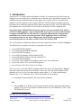
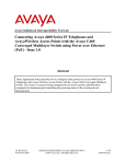
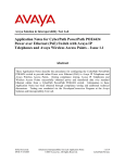
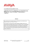
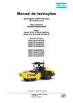
The Avaya product configurations addressed by these Application Notes are shown in Figure 1.
The following Avaya products are directly connected to the switch:
•
•
•
•
•
•
•
•
•
Avaya 4602SW SIP telephone
Avaya 4602 and 4602SW IP telephones
Avaya 4610SW IP telephone
Avaya 4620 IP telephone with and without EU24
Avaya 4620SW IP telephone with and without EU24
Avaya 4630SW IP telephone
Avaya Gen-1 4612 and 4624 IP telephones with Avaya 30A switch bases
Avaya Gen-2 4606, 4612, and 4624 IP telephones
Avaya Wireless AP-6 802.11a/b/g Access Point
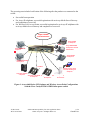
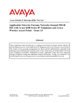
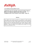
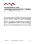
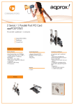
The Avaya Gen-1 4612 and 4624 IP telephones require the Avaya 30A Switch Base. Figure 2
shows the connections for the 30A switch base. The Avaya 4612 and 4624 telephones can be
identified as Gen-1 or Gen-2 by inspecting the model number. “1A” in the model number
indicates Gen-1; “2A” indicates Gen-2. The model number can be found by:
•
Inspecting the label attached to the bottom of the telephone.
OR
•
Pressing Mute, V, I, E, W, # on the keypad and then pressing * until the model number
appears. Press # to exit. Examples of model numbers are “4612D01A-003” (Gen-1) and
4612D02A-003 (Gen-2).
1
For details see Cisco PoE Product Snapshot at:
http://www.cisco.com/warp/public/cc/pd/si/casi/ca6000/prodlit/psnap_br.pdf (2004)
JZ; Reviewed:
WCH 11/24/2004
Solution & Interoperability Test Lab Application Notes
©2004 Avaya Inc. All Rights Reserved.
2 of 8
CiscoILP.doc
The powering tests included verification of the following after the product was connected to the
switch:
•
•
•
Successful boot operation
For Avaya IP telephones, successful registration with an Avaya Media Server/Gateway
and completion of a test call
For Wireless LAN Access Points, successful registration for an Avaya IP softphone with
an Avaya Media Server/Gateway and completion of a test call.
Avaya H.323/SIP
VoIP Infrastructure
Avaya 4630SW
IP Telephone
EU24
Avaya 4620/4620SW
IP Telephone with and
without EU24
Avaya 4602SW SIP
Telephone
Avaya 4610SW
IP Telephone
Avaya 4602 /4602SW
IP Telephone
30A Base
Wireless Laptop (Avaya
802.11b) with Avaya IP
Softphone
Avaya Gen-2 4606 IP
Telephone
Avaya Gen-1 4612/4624 Avaya Gen-2 4612/4624
IP Telephone
IP Telephone
Avaya AP-6
Access Point
Figure 1: Avaya 4600 Series IP Telephone and Wireless Access Point Configurations
with the Cisco Catalyst 3550-24 PWR inline power switch
JZ; Reviewed:
WCH 11/24/2004
Solution & Interoperability Test Lab Application Notes
©2004 Avaya Inc. All Rights Reserved.
3 of 8
CiscoILP.doc
Figure 2: Avaya 30A Switch Base Connections
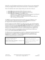
2. Equipment and Software Validated
The following equipment and software were used for the sample configuration provided:
Equipment
Cisco Catalyst 3550-24 PWR Inline Power Switch
Avaya 4602SW SIP Telephone
Avaya 4602 IP Telephone
Avaya 4602SW IP Telephone
Avaya 4606 IP Telephone
Avaya 4610SW IP Telephone
Avaya 4620SW IP Telephone
Avaya 4620 IP Telephone
Avaya 4630SW IP Telephone
Avaya 4612/4624 Gen-1 IP Telephone with 30A switch
Avaya 4612/4624 Gen-2 IP Telephone
Avaya Wireless AP-6 Access Point
Avaya 30A Ethernet Switch Base
Software
12.1(22)EA1
1.0.6
1.8.2
1.8.2
1.8.2
2.1.1
2.1.2
2.1.1
2.0.1
1.8.2
1.8.2
2.4.5(758)
-
Table 1 - Network Components and Software Versions
3. Configuring Catalyst 3550 Inline Power
The Catalyst 3550-24 PWR switch supports Cisco pre-standard PoE. All 24-port configurations
support 24 simultaneous full powered PoE ports at 15.4 Watts for maximum powered device
support.
This section describes the commands that can be issued to monitor and control inline power
status of the switch ports. All switch ports (or interfaces) have inline power set to auto as
JZ; Reviewed:
WCH 11/24/2004
Solution & Interoperability Test Lab Application Notes
©2004 Avaya Inc. All Rights Reserved.
4 of 8
CiscoILP.doc
default. The Avaya IP telephones and Wireless Access Points will receive power automatically
when they are plugged into the switch port if the switch senses a “maintain power signature”.
Three CLI commands can be used to configure inline power status for a switch port:
•
•
•
power inline never permanently disables inline-power on a port.
power inline auto sets the switch port to supply power automatically.
power inline delay {shutdown seconds initial seconds}
o shutdown seconds: Configure the time that the switch continues to provide power
to the device after linkdown. The range is 0 to 20 seconds.
o Initial seconds: Configure an initial time that the power shutdown delay is in
effect. The range is 0 to 300 seconds.
The initial time period begins when the PD is detected by the switch. If linkdown occurs
on the connected device during the initial time period, the shutdown time determines
how long the switch continues to provide power to the device.
In order to support Avaya 4602, 4602SW, Gen-2 4606, Gen-2 4612, Gen-2 4624 IP telephones,
and Avaya Wireless AP-6 Access Point, the power inline delay shutdown must be configured.
Note however that when the power inline delay shutdown command is active on a port, the port
remains powered after unplugging the PD for the configured time interval. To avoid product
damage, any non-IEEE power device must not be connected during the delay shutdown time
interval. For these reasons, it is recommended to dedicate all the PoE ports to IEEE power
devices using the power inline delay shutdown command.
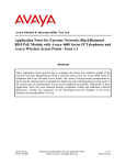
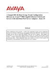
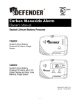
The following screen is the annotated port (or interface) configuration. Note that all switch ports
have inline power set to auto as default, which does not appear in the configuration. The
shutdown time is configured to 5 seconds and initial time to 100 seconds for the testing.
Customers can tune these timers to meet their need.
interface FastEthernet0/1
switchport access vlan 88
switchport mode access
power inline delay shutdown 5 initial 100
spanning-tree portfast
JZ; Reviewed:
WCH 11/24/2004
Native VLAN configuration
Configure switch mode to access
Configure delay shutdown times
Enable portfast for an IP
telephone
Solution & Interoperability Test Lab Application Notes
©2004 Avaya Inc. All Rights Reserved.
5 of 8
CiscoILP.doc
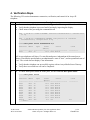
4. Verification Steps
The following CLI session demonstrates connection, verification, and control of an Avaya IP
telephone.
Steps
1.
•
•
•
Description
Connect an Avaya IP telephone as shown in Figure 1 to Ethernet port 0/1 on the switch.
Verify that the telephone is powered and is booting by inspecting the display.
Check status of the port using the command shown.
*Mar 1 20:49:31: %LINK-3-UPDOWN: Interface FastEthernet0/1, changed state
to up
*Mar 1 20:49:32: %LINEPROTO-5-UPDOWN: Line protocol on Interface
FastEthernet0/1, changed state to up
C3550#show power inline fastEthernet 0/1
Interface
Admin
Oper
Power
Device
(Watts)
---------- ----- ---------- ------- ------------------Fa0/1
auto on
15.0 Ieee device
Class
----------
All Avaya telephones will show 15 watts allocated power, independent of the actual power
drawn. Note that the port defaults to an administrative state of “auto”, and an operational state of
“on”. The switch does not display Class information.
2.
•
•
Verify that the telephone can successfully register with an Avaya Media Server/Gateway.
Verify that a successful test call can be completed.
•
To check inline power status on all the ports, use the command show power inline.
C3550#show power inline
Interface
Power
(Watts)
---------- ----- ---------- ------Fa0/1
auto on
15.0
Fa0/2
auto on
15.0
Fa0/3
auto on
15.0
Fa0/4
auto on
15.0
Fa0/5
auto on
15.0
Fa0/6
auto on
15.0
Fa0/7
auto on
15.0
Fa0/8
auto on
15.0
Fa0/9
auto on
15.0
Fa0/10
auto off
0.0
--More--
JZ; Reviewed:
WCH 11/24/2004
Admin
Oper
Device
Class
------------------Ieee device
Ieee device
Ieee device
Ieee device
Ieee device
Ieee device
Ieee device
Ieee device
Ieee device
n/a
----------
Solution & Interoperability Test Lab Application Notes
©2004 Avaya Inc. All Rights Reserved.
n/a
6 of 8
CiscoILP.doc
5. Conclusion
The Cisco 3550-24 PWR inline power switch can provide inline power to Avaya 4612/4624
Gen-1 IP telephones with Avaya 30A switch bases, Avaya 4610SW, 4620, 4620SW, 4630SW IP
telephones, and Avaya 4602SW SIP telephone. The switch can also provide inline power to
Avaya 4602, 4602SW, 4606 Gen-2, 4612/4624 Gen-2 IP telephones and Avaya Wireless AP-6
Access Point when the power inline delay shutdown is configured.
The Avaya IP telephones and Wireless Access Points are designed to the IEEE 802.3af-2003
standard. Since Cisco does not claim that the Cisco 3550 is compliant with the IEEE
802.3af-2003 standard2, the configurations described in these Application Notes is not
supported by Avaya. These Application Notes do not imply successful operation of any
other configurations not specifically mentioned here or future versions of the Cisco 3550.
2
For details see Cisco PoE Product Snapshot at:
http://www.cisco.com/warp/public/cc/pd/si/casi/ca6000/prodlit/psnap_br.pdf (2004)
JZ; Reviewed:
WCH 11/24/2004
Solution & Interoperability Test Lab Application Notes
©2004 Avaya Inc. All Rights Reserved.
7 of 8
CiscoILP.doc
©2004 Avaya Inc. All Rights Reserved.
Avaya and the Avaya Logo are trademarks of Avaya Inc. All trademarks identified by ® and ™
are registered trademarks or trademarks, respectively, of Avaya Inc. All other trademarks are the
property of their respective owners. The information provided in these Application Notes is
subject to change without notice. The configurations, technical data, and recommendations
provided in these Application Notes are believed to be accurate and dependable, but are
presented without express or implied warranty. Users are responsible for their application of any
products specified in these Application Notes.
Please e-mail any questions or comments pertaining to these Application Notes along with the
full title name and filename, located in the lower right corner, directly to the Avaya Solution &
Interoperability Test Lab at [email protected]
JZ; Reviewed:
WCH 11/24/2004
Solution & Interoperability Test Lab Application Notes
©2004 Avaya Inc. All Rights Reserved.
8 of 8
CiscoILP.doc