1
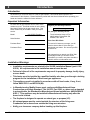
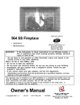
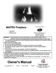
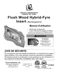
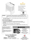
564 SS GreenSmart™
Fireplace
•
•
WARNING:
Tested and Listed by
OMNI-Test Laboratories, Inc.
Beaverton, Oregon
Report # 028-F-80b-5
ANSI Z21.88a-2003
Operation
Maintenance
If the information in these instructions is not followed exactly, a fire or
explosion may result causing property damage, personal injury or loss of
life.
-
Do not store or use gasoline or other flammable vapors and liquids in the vicinity of this
or any other appliance.
WHAT TO DO IF YOU SMELL GAS
• Do not try to light any appliance.
• Do not touch any electrical switch; do not use any phone in your building.
• Immediately call gas supplier from a neighbor's phone. Follow the gas supplier's
instructions.
• If you cannot reach your gas supplier, call the fire department.
- Installation and service must be performed by a qualified installer, service agency or the
gas supplier.
This appliance may be installed in an aftermarket permanently located, manufactured home (USA only) or
mobile home, where not prohibited by local codes.
This appliance is only for use with the type(s) of gas indicated on the rating plate. A conversion kit is
supplied with the appliance.
Owner's Manual
www.travisproducts.com
© Copyright 2008, T.I.
$10.00
100-01211_000
4081205
4800 Harbour Pointe Blvd. SW
Mukilteo, WA 98275
2
Introduction
Introduction
We welcome you as a new owner of a 564 SS gas fireplace. This manual details operation and
maintenance of this fireplace. Please familiarize yourself with the Owner's Manual before operating your
heater and save the manual for future reference.
Important Information
No other 564 SS gas fireplace has the same serial
number as yours. The serial number is on the listing
label that is chained to the gas control valve. This
serial number may be needed in case you require
service.
Model:
564 SS GS Fireplace
Register your warranty online at:
traviswarranty.com
Or, mail your warranty card to:
Travis Industries House of Fire
4800 Harbour Pointe Blvd. SW
Mukilteo, WA 98275
Serial Number:
Save Your Bill of Sale.
Purchase Date:
To receive full warranty coverage, you will
need to show evidence of the date you
purchased your heater. Do not mail your Bill
of Sale to us.
Purchased From:
We suggest that you attach your Bill of Sale
to this page so that you will have all the
information you need in one place should the
need for service or information occur.
Installation Warnings
•
Installation requirements are printed in the 564 SS Installation Manual (part # 10001210). All requirements in the installation manual must be met.
•
Failure to follow all of the requirements may result in property damage, bodily injury,
or even death.
•
This heater must be installed by a qualified installer who has gone through a training
program for the installation of direct vent gas appliances.
•
This appliance must be installed in accordance with all local codes, if any; if not,
follow ANSI Z223.1 and NFPA 54(88).
•
In Manufactured or Mobile Homes must conform with Manufactured Home
Construction and Safety Standard, Title 24 CFR, Part 3280, or, when such a standard
is not applicable, the Standard for Manufactured Home Installations, ANSI/NCSBCS
A225.1. This appliance may be installed in Manufactured Housing only after the
home is site located.
•
The fireplace is designed to operate on natural gas, or propane (LP).
•
All exhaust gases must be vented outside the structure of the living-area.
Combustion air is drawn from outside the living-area structure.
•
Notify your insurance company before hooking up this fireplace.
© Travis Industries
4081205
100-01211_000
Introduction
3
Table of Contents
Introduction and Important Information
Maintenance
Introduction ......................................................................... 2
Important Information .......................................................... 2
Installation Warnings ........................................................... 2
Features .............................................................................. 3
Heating Specifications ......................................................... 3
Safety Precautions
Safety Precautions .............................................................. 4
Operation
Before You Begin ................................................................ 6
Location of Controls ............................................................ 6
Starting the Fireplace for the First Time .............................. 7
Turning the Fireplace On and Off ........................................ 7
Comfort Control ................................................................... 7
Adjusting the Flame Height ................................................. 8
Accent Light ........................................................................ 8
Adjusting the Optional Blower Speed .................................. 9
Continuous Pilot / GreenSmart™ Pilot Switch..................... 9
Normal Operating Sounds ................................................... 10
Normal Operating Odors ..................................................... 10
Maintaining Your Fireplace's Appearance........................... 11
Battery Replacement .......................................................... 11
Accent Light Replacement .................................................. 12
Yearly Service Procedure ................................................... 12
Grill Installation and Removal ............................................. 13
Face Installation and Removal ............................................ 14
Glass Frame Removal and Installation ............................... 15
Log Set Installation ............................................................. 17
Glass Cleaning ................................................................... 24
Troubleshooting Table ........................................................ 25
Wiring Diagram .................................................................. 26
Replacement Parts List ....................................................... 26
Warranty
Warranty ............................................................................. 27
Optional Equipment
Optional Equipment List ...................................................... 28
Index
Index ................................................................................... 30
Features
•
•
•
•
•
Works During Power Outages (battery backup)
Optional GreenSmart™ Thermostat / Remote Control
Realistic "Wood Fire" Look
Optional Blower for Effective Heat Distribution
Built-In Accent Light (night light)
•
•
•
•
Built-In Control Panel Light
Standing or Intermittent (GreenSmart) Pilot
Convenient Operating Controls
Variable-Rate Heat Output
•
Low Maintenance
Heating Specifications
Natural Gas
Approximate Heating Capacity (in square feet)*
*
Propane
950
950
Maximum BTU Input Per Hour
20,500
20,500
Minimum BTU Input on Low
5,100
4,200
Heating capacity will vary with floor plan, insulation, and outside temperature.
© Travis Industries
4081205
100-01211_000
4
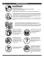
Safety Precautions
IF YOU SMELL GAS:
* Do not light any appliance
* Extinguish any open flame
* Do not touch any electrical switch or plug or unplug anything
* Open windows and vacate building
* Call gas supplier from neighbor's house, if not reached, call fire department
This unit must be installed by a qualified installer to prevent the possibility of an explosion.
Your dealer will know the requirements in your area and can inform you of those people
considered qualified. The room heater should be inspected and cleaned before use and
at least annually by a qualified service person. More frequent cleaning may be required
due to excessive lint from carpeting, bedding material, etc.
The instructions in this manual must be strictly adhered to. Do not use makeshift methods
or compromise in the installation. Improper installation will void the warranty and safety
listing.
This heater is either approved for natural gas (NG) or for propane (LP). Burning
the incorrect fuel will void the warranty and safety listing and may cause an
extreme safety hazard. Direct questions about the type of fuel used to your dealer.
Check for a label on the flame adjust knob on the gas control valve (this is the best
place to check). You may also check for a label on the gas control valve body.
Ok
Gas
© Travis Industries
Contact your local building
officials to obtain a permit and
information on any installation
restrictions or inspection
requirements in your area.
Notify your insurance company
of this heater as well.
If the flame becomes sooty, dark
orange in color, or extremely tall,
do not operate the heater. Call
your dealer and arrange for
proper servicing.
It is imperative that control
compartments, screens, or
circulating air passageways of
the heater be kept clean and
free of obstructions. These
areas provide the air necessary
for safe operation.
Do not operate the heater if it is
not operating properly in any
fashion or if you are uncertain.
Call your dealer for a full
explanation of your heater and
what to expect.
Do not store or use gasoline or
other flammable liquids in the
vicinity of this heater.
4081205
?
Do not operate if any portion of
the heater was submerged in
water or if any corrosion occurs.
Immediately call a qualified
service technician to inspect the
appliance and to replace any part
of the control system and any
gas control that has been under
water.
100-01211_000
Safety Precautions
Light the heater using the built-in
igniter. Do not use matches or
any other external device to light
your heater.
Do not place clothing or other
flammable items on or near the
heater. Because this heater can
be controlled by a thermostat
there is a possibility of the
heater turning on and igniting
any items placed on or near it.
Allow the heater to cool before
carrying out any maintenance or
cleaning.
The viewing glass should be
opened only for conducting
service. Do not operate with
cracked, broken, or removed
glass.
Never remove, replace, modify or
substitute any part of the heater
unless instructions are given in
this manual. All other work must
be done by a trained technician.
Don't modify or replace orifices.
Any safety screen or guard
removed for servicing must be
replaced prior to operating the
heater.
Instruct everyone in the house
how to shut gas off to the
appliance and at the gas main
shutoff valve. The gas main
shutoff valve is usually next to
the gas meter or propane tank
and requires a wrench to shut off.
Operate the heater according to
the instructions included in this
manual.
If the main burners do not start
correctly turn the gas off at the
gas control valve and call your
dealer for service.
This unit is not for use with solid
fuel
Do not place anything inside the
firebox (except the included fiber
logs).
5
This
Manual
Do not throw this manual away.
This manual has important
operating and maintenance
instructions that you will need at
a later time. Always follow the
instructions in this manual.
If the fiber logs become
damaged, replace with Travis
Industries log set.
Children and adults should be
alerted to the hazards of high
surface temperature and should
stay away to avoid burns or
clothing ignition. Young children
should be supervised when they
are in the same room as the
heater.
© Travis Industries
4081205
Travis Industries, Inc. grants
no warranty, implied or stated,
for the installation or
maintenance of your heater,
and assumes no responsibility
of any consequential
damage(s).
100-01211_000
6
Operation
Before You Begin
•
Read this entire manual before you use your new fireplace (especially the section "Safety
Precautions" on pages 4 & 5). Failure to follow the instructions may result in property damage, bodily
injury, or even death.
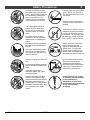
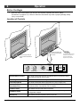
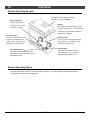
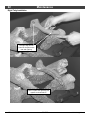
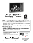
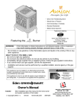
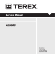
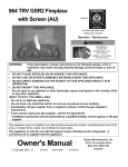
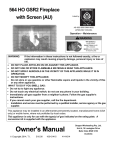
Location of Controls
Swing the concelament cover
Lift up and swing the lower grill
up and slide it back to expose
An instruction card for operating
the controls.
the fireplace is attached to the
down to acces the area below the
inside of the fireplace here.
firebox.
Replace it for easy reference.
HIGH
HIGH
FLAME ADJUST
HIGH
OFF
OFF
CONTINUOUS
COMFORT
PILOT
CONTROL
MAIN
AA
BURNER
BATTERY
LOW
LOW
HOLDER
LOW
BLOWER
ACCENT LIGHT
GREEN
SMART
PILOT
Optional Blower Control
This knob controls the speed of the optional internal convection blower
that pushes heated air into the room.
Accent Light
This knob controls the accent lights located behind the logs.
Flame Adjust Knob
This knob controls the flame height from low ("LO") to high ("HI").
Continuous Pilot -GreenSmart Pilot
This switch controls how the pilot flame works. See the section
“Continuous Pilot / GreenSmart Pilot” for details.
Comfort Control
This switch turns the rear burner on and off.
AA Battery Holder
This holder contains 4 AA batteries that allow the fireplace to operate
during power outages.
Main Burner
This switch turns the fireplace burners on and off.
© Travis Industries
4081205
100-01211_000
Operation
7
Starting the Fireplace for the First Time
•
Burn the heater at a high setting with the blower off for an extended period (up to 48 hours). This will
cure the painted surfaces. Fumes from the paint curing and oil burning off the steel will occur. This
is normal. We recommend opening a window to vent the room.
•
Condensation may appear on the glass each time you start the fireplace - this is normal.
•
Blue Flames will occur on the fireplace when it first comes on. After fifteen minutes the flames will
turn a more realistic yellow and orange color.
•
Certain installations use a remote, thermostat, or wall switch to turn the fireplace on and off. If this is
the case, leave the ON/OFF switch "ON".
•
Verify the power backup and control light batteries are installed (see page 11).
Turning the Fireplace On and Off
Use the main burner switch to turn the main burner on and off.
MAIN
BURNER
ON
OFF
NOTE FOR REMOTES, THERMOSTATS, OR WALL SWITCHES:
The on/off switch on the fireplace may be required to be left in the ON or OFF position for the fireplace to
operate. Consult your installer or dealer for details.
•
Do not place any combustible items on top of or directly in front of the fireplace, even temporarily. An
optional thermostat may start the fireplace causing a combustible item to ignite.
•
If the fireplace turns on and off frequently while using the thermostat, you may want to adjust the
flame height down until it produces just enough heat needed.
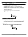
Comfort Control
The rear portion of the burner may be shut off to lower the heat output and flame size from the burner
(this is called the comfort control). Use the comfort control switch to adjust this as desired.
COMFORT
CONTROL
© Travis Industries
4081205
100-01211_000
8
Operation
Adjusting the Flame Height
This fireplace has an adjustable flame to tailor the look and heat output to your specific needs. It is
adjusted by turning the flame adjust knob.
FLAME ADJUST
HIGH
LOW
Accent Light
This fireplace has a built-in accent light that may be turned on and off and dimmed to your preference.
Turn the knob to achieve the desired light output.
HIGH
OFF
LOW
ACCENT LIGHT
OFF
© Travis Industries
LOW
4081205
HIGH
100-01211_000
Operation
9
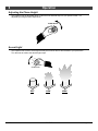
Adjusting the Optional Blower Speed
The blower helps transfer heat from the heater into the room. It will not turn on until the heater is up to
temperature (approximately 15 minutes after starting). See the illustration below for instructions on
adjusting the blower speed.
NOTE:
With the rear burner off (comfort control), the heater may not become hot enough for the
blower to turn on.
HIGH
OFF
LOW
BLOWER
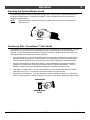
Continuous Pilot / GreenSmart™ Pilot Switch
This fireplace may run with the pilot continuously running or in GreenSmart (intermittent) mode. For most
homeowners, the GreenSmart mode is preferred (this saves fuel, doesn’t give off un-needed heat).
However, in some situations the homeowner may prefer to switch the fireplace to continuous pilot. The
most typical reasons for switching to continuous pilot are:
•
Very Cold Conditions – in very cold conditions you may notice that the burner does not light quickly,
and the flames lift off the burner. If this is situation, we recommend you switch to continuous pilot.
This will create a slight draft in the vent, allowing for the burner to light quickly and draft correctly.
•
Excessive Condensation on Glass After Startup – certain installations may encounter excessive
fogging on the window after stuartup (not just the first time the fireplace was started). This is an
aesthetic condition that may be remedied by switching the fireplace to continuous pilot.
•
Cold Glass or Fireplace Front – in very cold conditions you may notice that the fireplace front and
glass become very cold. To remedy this, switch the fireplace to continuous pilot.
•
Frequent On / Off Operation – if you are frequently turning the fireplace on and off, you may wish to
leave it in continuous pilot. This allows the burner to turn on more quickly, without pilot ignition delay.
CONTINUOUS
PILOT
GREEN SMART
PILOT
© Travis Industries
4081205
100-01211_000
10
Operation
Normal Operating Sounds
The appliance may creak with change of
temperature -- THIS IS NORMAL.
Blower Snap Disk
This part can produce a
clicking sound as it turns
the blower on and off.
Blowers
This heater has optional blowers to push
heated air into the room. You will hear the
sound of air movement that increases as
the speed is increased.
Gas Control Valve
As the gas control valve is turned
on and off you will hear a dull
clicking sound. This is the valve
opening up and shutting down.
Extinction Pops
It is not unusual, especially on Propane
(LP) appliances, to experience a "pop"
when the burner is shut off.
Pilot Assembly
The pilot flame will make a clicking
sound when starting up. If left on, it
will make a slight whisper sound.
GreenSmart Receiver
The optional GreenSmart receiver will
beep when receiving commands from the
GreenSmart remote.
Normal Operating Odors
This appliance has several areas that reach high temperatures. Dust or other particles on these areas
may burn and create an odor. This is normal during start-up. You may notice the smell is more acute if
the appliance was left idle for a long period.
© Travis Industries
4081205
100-01211_000
Maintenance
11
Maintaining Your Fireplace's Appearance
Fingerprints or other marks left on the optional plated surface may become etched in place if they are not
wiped clean prior to turning the fireplace on. Clean the plated surface with denatured alcohol and a soft
cloth (with the fireplace cool). Other cleaners may leave a film that may become etched into the surface.
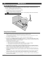
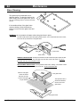
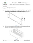
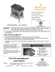
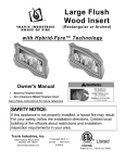
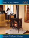
Battery Replacement
Power Backup Batteries
Four AA batteries are used as a power backup for the fireplace in case the household (AC) power goes out.. These
batteries must be inserted into battery holder (see the illustration below). The fireplace controller will beep once these
batteries start to go dead. Replace batteries before each heating season to insure proper operation.
Control Panel Light Battery
LED lights and a 9v battery are used to illuminate the control panel when the concealment cover is lifted. If the LED
lights do not operate, replace the 9v battery (see the illustration below). The battery holder is held in place with Velcro
and may be removed for easier access.
Battery Holder for Control
Panel Lights
9
Ba v
tte
ry
AA
Lift up and swing the lower grill
AA
Ba
Ba
tte
tte
ry
ry
down to acces the area below the
firebox.
Swing the concealment cover
up and slide it back to expose
AA Battery
the controls.
AA
AA
Ba
tte
Ba
ry
tte
ry
Holder
AA Battery Tray
© Travis Industries
4081205
100-01211_000
12
Maintenance
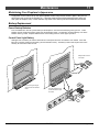
Accent Light Replacement
Two accent lights are included in your fireplace to provide additional lighting. These bulbs will burn out
over time. To replace, follow the directions below:
•
Shut off gas to the fireplace and let it cool for 15 minutes.
•
Remove the glass (see page 15) and logs (see page 17).
•
Replace the halogen bulbs with the following bulbs:
(NOTE: .Take care to not touch the bulb with your fingers – use foam packing or paper towel to hold the bulb):
35 Watt 120 Volt T4 Halogen Bulb (G6.35 Base)
Yearly Service Procedure
•
Failure to inspect and maintain the fireplace may lead to improper combustion and a potentially dangerous
situation. We recommend the following procedures be done by a qualified technician.
1.
Turn the pilot flame to continuous. It should touch approximately 3/8" of the top of the flame sensor. If it does
not, contact your dealer for service.
2.
Shut off gas to the fireplace and let it cool for 15 minutes. Remove the glass (see page 15).
3.
Remove the log set (NOTE: the logs are very fragile - see page 17). If severely deteriorated, replace. Check
the logs for sooting. A small amount of soot along the bottom of the logs is normal. If excessive sooting is found,
the fireplace will require adjustment. Contact your dealer.
4.
Inspect the burner and remove any debris.
•
•
•
Make sure the burner is not warped, cracked, or damaged.
Check the firebox and area around the pilot to make sure there is no warping or damage.
If any problem is found, discontinue use and contact your dealer for service.
5.
Replace the log set. Clean and replace the glass (see Glass Cleaning on page 24). If the glass is damaged,
replace. Make sure the gasket along the perimeter of the glass contacts the face of the firebox and forms an airtight seal. If it does not, re-align or replace the gasket to insure an air-tight seal.
6.
Inspect the area behind the access door. Clean if necessary. Check the gas control valve and the gas lines. If
damage is found, discontinue use and contact your dealer for service. Clean the air channels, ducts, and blower
(if applicable).
7.
Start the main burner. After 15 minutes the flames should be orange/yellow and not touch the top of the firebox.
If the pilot or main burners do not burn correctly, contact your dealer for service. Monitor blower operation.
8.
Remove any debris or vegetation near the vent termination. Contact your dealer if any sooting or deterioration is
found near the vent termination.
© Travis Industries
4081205
100-01211_000
Maintenance
13
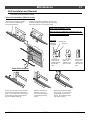
Grill Installation and Removal
Follow the directions below to install.
Upper Grill Installation (FPX and Avalon)
Hold the grill at an angle and insert the
lower slot over the lower bushing on
the fireplace (both sides)
Swing the grill upwards to engage the upper slot. You
will need to lift the grill slightly to get it over the bushing.
Once in place the grill is held in place by gravity.
Upper Grill Installation (Lopi)
NOTE: The upper grill is difficult to install the first time - be
patient, after you install it, you will know how it installs and it
will be much easier the second time.
SIDE VIEW
Mounting Stud
Heat Shields
(on fireplace)
Position the grill
so the slots on
the grill align with
the mounting
studs.
Upper Grill
You may need to
push in and
upwards on the
grill as it inserts.
The grill, when
fully inserted,
will slide down
and “click” into
place.
Lower Grill Installation
Hold the grill at an angle and insert the lower
slot over the bushing on the fireplace (both
sides). You may need press on the grill to get
the tab over the bushing (this prevents the
grill from accidentally falling off).
© Travis Industries
Bend the tab outward on
both sides. This is the
end-stop for the lower grill,
it allows the grill to swing
forward.
4081205
Swing the grill upwards to engage
the upper slot. You will need to lift
the grill slightly to get it over the
bushing. Once in place the grill is
held in place by gravity.
100-01211_000
14
Maintenance
Face Installation and Removal
Some fireplaces have a face that fits over the glass frame. The face can be removed following the
directions below.
Phillips
Screwdriver
Four screws hold the face
in place. The screws are
accessed through the
grills on the face.
© Travis Industries
4081205
100-01211_000
Maintenance
15
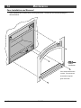
Glass Frame Removal and Installation
Warning:
The appliance must be completely cool before removing the glass.
Warning:
Do not strike or slam the glass.
a
Based upon the face being used, either:
(a) swing the access door down and remove the top grill,
(b) remove the face (unscrew or lift off - see the instructions
included with the face for details).
Open the four latches holding the glass frame in place (start
with the bottom) - follow the directions shown to the right.
Top of
Firebox
Latch
Glass
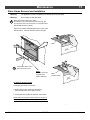
b
Lift the glass frame up and
pull it forward to remove.
NOTE:
You may need to lift
the glass frame
while re-attaching.
Catch
(on glass frame)
Re-Attaching the Glass Frame:
a) Hang the glass frame on the firebox.
b) While holding in place, attach the upper latches
(follow the instructions to the right in reverse).
c) Lift the glass frame slightly and attach the lower latches.
NOTE: Make sure the glass frame is all the way in place - it
should be flush with the front of the fireplace when installed.
© Travis Industries
4081205
100-01211_000
16
Maintenance
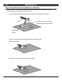
Glass Frame Removal and Installation (continued)
The latch can come loose from the latch assembly. This occurs only when it is rotated. Follow the
directions below to re-install the latch if it comes loose.
Hold the latch at an angle and insert it into the slot on the glass frame anchor.
Latch
NOTE: this slot may be at a
different angle than illustrated.
Top of
Firebox
Glass Frame
Anchor
Note how the washer on the latch fits behind the flange on the
glass frame anchor.
Once fully inserted, turn the latch until it is upright.
© Travis Industries
4081205
100-01211_000
Maintenance
17
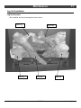
Log Set Installation
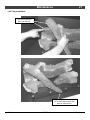
Log Set Overview
When installed, the logs should appear as shown below.
Rear Log
Left Log
© Travis Industries
Right Twig
Left Twig
4081205
Right Log
100-01211_000
18
Maintenance
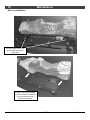
Rear Log Installation
The rear log has a flat notch
on both sides that center it
on the grate.
Place the rear log on the grate
and slide it all the way back until
the log contacts the endbrackets on the grate.
© Travis Industries
4081205
100-01211_000
Maintenance
19
Right Log Installation
The left log has a groove
that fits over the grate.
Note how the left side of the log
rests on the burner but does not
cover any burner holes.
© Travis Industries
4081205
100-01211_000
20
Maintenance
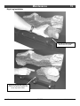
Left Log Installation
The left log has a groove
that fits over the grate.
Note how the right side of the log
rests on the burner but does not
cover any burner holes.
© Travis Industries
4081205
100-01211_000
Maintenance
21
Left Twig Installation
This hole fits over the
pin on the rear log.
The left twig should be positioned
so the front edge contacts the
grate as shown above.
© Travis Industries
4081205
100-01211_000
22
Maintenance
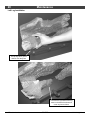
Right Twig Installation
The right twig has two
holes for the pins on the
rear and right log.
When in place the right twig will
appear as shown above.
© Travis Industries
4081205
100-01211_000
Maintenance
23
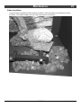
Ember Installation
A bag of embers is provided to further enhance the firebox. Place the embers on the firebox floor and on
the burner. Do not place embers over any of the burner holes or air channels.
© Travis Industries
4081205
100-01211_000
24
Maintenance
Glass Cleaning
The glass may be cleaned with a nonabrasive cleaner. To clean the inside of the
glass, simply remove the glass frame, place it
on a non-scratching surface, and clean the inside
surface.
If the outside surface of the glass frame
requires cleaning, follow the directions
below to remove the outer glass frame and
screen.
WARNING: do not operate the fireplace without the glass frame in place.
Six sets of tabs hold the glass (and glass gasket) in place. Four of these tabs are at the corners,
two are at the top and bottom of the glass frame.
Gasket
Inner Frame
Tabs
Outer Frame
REMOVAL INSTRUCTIONS: carefully bend the tabs out with needle-nose pliers (there are tabs
on the inner and outer frame - the center tabs only have tabs on the inner frame). Do not pry
these tabs, this may cause the glass to crack.
REPLACEMENT INSTRUCTIONS: carefully bend the tabs inward, making sure the tabs contact
the gasket, not the glass. Bend the tab inwards 30°- do not over-bend the tabs.
With the outer glass
frame and screen
Inner glass frame
removed, the outer
surface of the glass
may be cleaned.
The optional screen is
sandwiched between
the inner and outer
glass frame.
Outer glass frame
© Travis Industries
4081205
100-01211_000
Maintenance
25
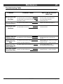
Troubleshooting Table
Problem:
Main Burners Will
Not Start
Receiver Beeps
Thermostat Does
Possible Cause:
Don't Call for Service
Until You:
The ON/OFF switch is turned to "OFF"
Turn the ON/OFF switch to "ON"
The remote control is not working correctly
See the remote control instructions
The thermostat is disconnected or set too low
See "Thermostat Operation"
No Propane in Tank
Check Tank Level
The power backup batteries are dead
Replace the batteries (see page 11)
The ON/OFF switch is turned to "OFF"
Turn the ON/OFF switch to "ON"
The thermostat is set too low
Check thermostat
The fireplace is not getting electricity
Check the breaker switch
The fireplace is not up to temperature
Let the fireplace burn for at least 15
minutes
The fireplace has just been started
This is normal - see "Starting the Fireplace
for the First Time"
Improper air shutter adjustment
Adjust Air Shutter - contact your dealer
The flame height may be turned too low
Turn the flame height to "HI" See "Adjusting the Flame Height"
The logs or coals are placed incorrectly
See "Log Set Installation"
Improper air shutter adjustment
Adjust Air Shutter - contact your dealer
Not Work
Fireplace Will Not
Distribute Heat
Flames Are Too
Blue
Flames Are Too
Short (Under 6")
Thin Layer of Soot
Covers the Glass
© Travis Industries
4081205
100-01211_000
26
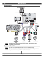
Maintenance
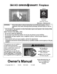
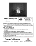
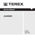
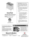
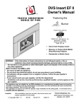
Wiring Diagram
Spark Rod
Pilot
Sensor
Pilot Ground
CN4
Comfort Control
Valve
PILOT
SENSOR
DIGITAL
FIREPLACE
CN0
BURNER
CONTROL
SPARK ROD
VALVE
CN3
CN2
DIAGNOSTIC
COMMAND
POWER
CN1
GROUND
POWER SUPPLY
IPI / CPI
Blue
Red
Black
Red
Red
Red
ON / OFF
Black
Blue
Red
Green
Orange
Yellow / Green
VALVE
AC
ADAPTER
Green
White
Black
Blue
White
CONTINUOUS
PILOT
GREENSMART
PILOT
Caution:
COMFORT
CONTROL
AA
BATTERY
TRAY
MAIN BURNER
Label all wires prior to disconnection when servicing controls. Wiring errors can cause
improper and dangerous operation.
Replacement Parts List
Caution:
Use only Travis Industries replacement parts. Do not use substitute materials.
Warning:
Do not operate appliance with the glass front removed, cracked, or broken. Replacement of
the glass should be done by a licensed or qualified service person.
© Travis Industries
4081205
100-01211_000
Limited 7 Year Warranty
27
Register your TRAVIS INDUSTRIES, INC. Limited 7 Year Warranty online at traviswarranty.com, or complete the enclosed Warranty card and mail it within ten (10)
days of the appliance purchase date to: TRAVIS INDUSTRIES, INC., 4800 Harbour Pointe Blvd. SW, Mukilteo, WA 98275. TRAVIS INDUSTRIES, INC. warrants
this gas appliance (appliance is defined as the equipment manufactured by Travis Industries, Inc.) to be defect-free in material and workmanship to the original
purchaser from the date of purchase as follows:
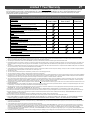
Check with your dealer in advance for any costs to you when arranging a warranty call.
Mileage or service charges are not covered by this warranty. This charge can vary from store to store.
Years 1 & 2
Parts & Labor
Component
Years 3 Through 5
Parts & Labor
Years 6 & 7
Parts Only
Burner Assembly
Burner Pan Assembly, Air Shutter Assembly, Main Burner Orifice
Electrical Assembly (within heater structure):
Wiring harness, snap discs, rheostat speed control
Gas Control Assembly
Adjustable control valve, fireplace controller, pilot assembly and pilot wiring
Glass
Glass (breakage from thermal shock)
Ceramic Logs
Log Set, Embers
Gold, Nickel & Copper Plating
Face & Door (see “Conditions and Exclusions” # 9)
Accessories
Firebacks, Power Heat Ducts, Andirons, etc…
One-Way Freight Allowance
One-way freight allowance on pre-authorized repair done at factory is covered.
Convection Heat Exchanger
Convection heat exchanger assembly
Firebox Assembly
Adjustable Air Restrictor, Pressure Relief Mechanisms, Glass Attachment Mechanism
EXCLUDED COMPONENTS:
Paint, Gasketing, and Accent Light Bulbs
CONDITIONS & EXCLUSIONS
1. This new gas appliance must be installed by a qualified gas appliance technician. It must be installed, operated, and maintained at all times in accordance with the instructions in the Owner’s
Manual. Any alteration, willful abuse, accident, neglect, or misuse of the product shall nullify this warranty.
2. This warranty is nontransferable, and is made to the ORIGINAL purchaser, provided that the purchase was made through an authorized TRAVIS dealer.
3. Discoloration and some minor expansion, contraction, or movement of certain parts and resulting noise, is normal and not a defect and, therefore, not covered under warranty. The installer must
ensure the appliance is burning as per the rating tag at the time of installation. Over-firing (operation above the listed BTU rate) of this appliance can cause serious damage and will nullify this
warranty.
4. The warranty, as outlined within this document, does not apply to the chimney components or other Non-Travis accessories used in conjunction with the installation of this product. If in doubt as to
the extent of this warranty, contact your authorized TRAVIS retailer before installation.
5. Travis Industries will not be responsible for inadequate performance caused by environmental conditions such as nearby trees, buildings, roof tops, wind, hills or mountains or negative pressure or
other influences from mechanical systems such as furnaces, fans, clothes dryers, etc.
6. This Warranty is void if:
a. The unit has been operated in atmospheres contaminated by chlorine, fluorine or other damaging chemicals.
b. The unit is subject to submersion in water or prolonged periods of dampness or condensation.
c. Any damage to the unit, combustion chamber, heat exchanger or other components due to water, or weather damage which is the result of, but not limited to, improper chimney/venting installation.
7. Exclusions to this 7 Year Warranty include: injury, loss of use, damage, failure to function due to accident, negligence, misuse, improper installation, alteration or adjustment of the manufacturer's
settings of components, lack of proper and regular maintenance, damage incurred while the appliance is in transit, alteration, or act of God.
8. This 7 Year warranty excludes damage caused by normal wear and tear, such as paint discoloration or chipping, worn or torn gasketing, corroded or cracked logs, embers, etc. Also excluded is
damage to the unit caused by abuse, improper installation, modification of the unit, drilling of the orifices, or the use of fuel other than that for which the unit is configured. Units are shipped for
natural gas and must be converted to propane using the included conversion kit. Confirm fuel configuration with your installer.
9. Damage to gold or nickel surfaces caused by fingerprints, scratches, melted items , or other external sources left on the gold or nickel from the use of cleaners other than denatured alcohol is not
covered in this warranty.
10. TRAVIS INDUSTRIES, INC. is free of liability for any damages caused by the appliance, as well as inconvenience expenses and materials. Incidental or consequential damages are not covered
by this warranty. In some states, the exclusion of incidental or consequential damage may not apply.
11. This warranty does not cover any loss or damage incurred by the use or removal of any component or apparatus to or from the gas appliance without the express written permission of TRAVIS
INDUSTRIES, INC. and bearing a TRAVIS INDUSTRIES, INC. label of approval.
12. Any statement or representation of TRAVIS products and their performance contained in TRAVIS advertising, packaging literature, or printed material is not part of this 7 year warranty.
13. This warranty is automatically voided if the appliance’s serial number has been removed or altered in any way. If the appliance is used for commercial purposes, it is excluded from this warranty.
14. No dealer, distributor, or similar person has the authority to represent or warrant TRAVIS products beyond the terms contained within this warranty. TRAVIS INDUSTRIES, INC. assumes no
liability for such warranties or representations.
15. Travis Industries will not cover the cost of the removal or re-installation of hearths, facing, mantels, venting or other components.
16. If for any reason any section of this warranty is declared invalid, the balance of the warranty remains in effect and all other clauses shall remain in effect.
17. THIS 7 YEAR WARRANTY IS THE ONLY WARRANTY SUPPLIED BY TRAVIS INDUSTRIES, INC., THE MANUFACTURER OF THE APPLIANCE. ALL OTHER WARRANTIES, WHETHER
EXPRESS OR IMPLIED, ARE HEREBY EXPRESSLY DISCLAIMED AND PURCHASER’S RECOURSE IS EXPRESSLY LIMITED TO THE WARRANTIES SET FORTH HEREIN.
IF WARRANTY SERVICE IS NEEDED:
1. If you discover a problem that you believe is covered by this warranty, you MUST REPORT it to your TRAVIS dealer WITHIN 30 DAYS, giving them proof of purchase, the purchase date, and the
model name and serial number.
2. Travis Industries has the option of either repairing or replacing the defective component.
3. If your dealer is unable to repair your appliance’s defect, he may process a warranty claim through TRAVIS INDUSTRIES, INC., including the name of the dealership where you purchased the
appliance, a copy of your receipt showing the date of the appliance’s purchase, and the serial number on your appliance. At that time, you may be asked to ship your appliance, freight charges
prepaid, to TRAVIS INDUSTRIES, INC. TRAVIS INDUSTRIES, INC., at its option, will repair or replace, free of charge, your TRAVIS appliance if it is found to be defective in material or
workmanship within the time frame stated within this 7 year warranty. TRAVIS INDUSTRIES, INC. will return your appliance, freight charges (years 1 to 5) prepaid by TRAVIS INDUSTRIES, INC.,
to your regional distributor, or dealership.
4.
Check with your dealer in advance for any costs to you when arranging a warranty call. Mileage or service charges are not covered by this warranty. This charge can vary from store to store.
© Travis Industries
4081205
100-01211_000
28
Optional Equipment
Accessories
The accessories listed below are available at your Travis dealer. To locate a dealer, visit:
www.travisproducts.com
GreenSmart™ Remote / Thermostat
This accessory allows for remote control of your fireplace (burner, flame height, accent light).. It has
a built-in thermostat if you wish for automatic temperature control.
°F
Blower
The optional blowers help transfer heat to your home.
Firebacks
There are several styles of decorative firebacks that fit inside the firebox and enhance the area
behind the flames.
© Travis Industries
4081205
100-01211_000
Optional Equipment
© Travis Industries
4081205
29
100-01211_000
30
Index
Index
Accent Light Replacement .................................................. 12
Accent Light ........................................................................ 8
Adjusting the Flame Height ................................................. 8
Adjusting the Optional Blower Speed .................................. 9
Battery Replacement .......................................................... 11
Before You Begin ................................................................ 6
Comfort Control................................................................... 7
Continuous Pilot / GreenSmart™ Pilot Switch .................... 9
Face Installation and Removal ............................................ 14
Features .............................................................................. 3
Glass Cleaning.................................................................... 24
Glass Frame Removal and Installation ............................... 15
Grill Installation and Removal ............................................. 13
Heating Specifications ........................................................ 3
Important Information .......................................................... 2
Index ................................................................................... 30
Installation Warnings ........................................................... 2
Introduction ......................................................................... 2
Location of Controls ............................................................ 6
Log Set Installation ............................................................. 17
Maintaining Your Fireplace's Appearance ........................... 11
Normal Operating Odors ..................................................... 10
Normal Operating Sounds................................................... 10
Optional Equipment List ...................................................... 28
Optional Screen (on glass) ................................................. 15
Replacement Parts List ....................................................... 26
Safety Precautions .............................................................. 4
Starting the Fireplace for the First Time .............................. 7
Troubleshooting Table ........................................................ 25
Turning the Fireplace On and Off........................................ 7
Warranty ............................................................................. 27
Wiring Diagram .................................................................. 26
Yearly Service Procedure ................................................... 12
© Travis Industries
4081205
100-01211_000