1
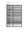
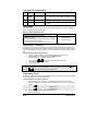
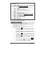
Keyless Entry And Alarm System CT-1010 Installation Guide Table of Contents Included in the Kit........................... 1 Installation Points to Remember .. 2 Programmable Features .................. 2 Harness Description......................... 3 How to Flash the Hood Pin........... 4 Programming a Transmitter........... 4 Programming Options .................... 4 Dome Light Delay............................ 7 Retain Accessory Output............... 7 Zone 2 Disable Output .................. 7 Multi-car Operation ........................ 7 Resetting the Module...................... 7 Diagnostics - Parking Lights Flash Rate ..................................................... 8 Closing Up ......................................... 8 Included in the Kit Please review the installation guide before beginning the installation, especially the wiring diagram and the programming options. It is very important that you familiarize yourself with the programming and operation of the system, even if you have already installed an alarm system in the past. There are many great new features that may be overlooked if the manual is not read: you would therefore not maximize the unit’s potential. Prior to the installation, make sure that all the hardware components required to install the system are in the box. Notice The manufacturer will accept no responsibility for any electrical damage resulting from improper installation of the product, be that either damage to the vehicle itself or to the Unit. This Unit must be installed by a certified technician using all safety devices supplied. Only registered technicians will be eligible to use the Prostart technical support telephone service. Please review the Installation Guide carefully before beginning any work. DOC: 1.06 November 10, 2006 TL Manufactured in Canada by Autostart The following is a list of components included in the kit: 1 – Control unit. 2- CT-200 transmitters 1 – plug-in L.E.D o 1 – user guide 1 – Hood-pin switch o 1 – installation guide. 1 – plug-in valet button. The kit also includes the following harnesses: o 1 – 2 pin Wire harness. o 1 – 12 pin principal auxiliary o 1 – 5 pin Main harness. harness o 1 – 3 pin connector cable o o o o o Installation Points to Remember o When working on a vehicle always leave a window open. o Never leave the keys in the car. Leave them on a workbench with a window rolled down. o If possible, remove courtesy light fuse to prevent battery drain. o Inspect vehicle for any body damage or electrical problems. o Make sure that all the switches and controls operate properly. o Verify that the vehicle starts and idles properly. o Never install control unit where it could interfere with normal operation or obstruct service technicians. o Do not disconnect the battery on vehicles equipped with air bags and anti-theft radios. o Always use a grommet when running wires into the engine compartment. o Never run wires through bare or sharp metal. o Always solder and tape all connections. o Never ground the control unit to the steering column of the vehicle. o When you probe /test the wires of a harness, make sure you check the plug-in connector. o The wires for the air bags aren’t always identified on the harness (split loom or a yellow tape). However they are always identified on the connector. o Keep the Transceiver away from other types of antennas (GPS/Onstar). o Make sure all security equipment is installed: the Valet switch, the hood pin and the warning label. Programmable Features The unit was designed with flexibility and OEM integration in mind. The system gives installers the output flexibility that every good installer is looking for; this unit can be customized and used for almost every possible application. With the integration of timed-latched and ON / OFF outputs, this unit can single-handedly control virtually any electrical system in the car! The programmable features are as follows: 1. Ignition-Controlled Door Locks • OFF by default. This feature will LOCK all the Doors of the vehicle while the Ignition Key is in the IGNITION ON (RUN) position and only when all the doors are closed (there is no recurrence of this action). The unit will UNLOCK all Doors when the Ignition Key is turned back to the OFF position. • If Ignition Lock Only is selected, the system will only LOCK all Doors while the Ignition Key is in the IGNITION ON (RUN) position and only when all the doors are closed (there is no recurrence of this action). • If option Ignition Unlock Only is selected, the system will UNLOCK all Doors when the key is turned to the OFF position (provided that the Ignition key was in the IGNITION ON (RUN) position). 2. Passive or Active Arming • (Passive with a 1-min. time out by default.) The alarm system on this unit can be set to active mode (in which it will not arm itself automatically) or to passive mode (arms itself automatically) with a 1-minute timeout. 3. Door Lock Pulse Duration • (¾-sec. lock and ¾-sec. unlock pulses by default.) This system can be programmed to give either 3.5sec. lock /unlock pulses (this is used to control vacuum door-lock system, for instance on Mercedes) or a single ¾ -sec. lock pulse with a double ¼-sec. unlock pulse (this is used for double-pulse disarm/unlock systems, as in the Maxima, Pathfinder, and Volkswagen…) P. 2 Installation Guide Alarm-050 4. Relock • If you unlock the doors with the remote transmitter, but do not open any door or trunk within 60 seconds, the doors will automatically relock. Harness Description 5 PIN HARNESS WIRE Wire colour 1 2 3 4 5 Function Description This wire must be connected to bare, unpainted metal (the (-) CHASSIS GROUND chassis or true body ground). It is preferable that you use a INPUT factory ground bolt rather than a self-tapping screw. Connect to the +12 V power feed of the vehicle, at the Ignition RED +12V POWER INPUT harness. The source wire should have +12 V without Ignition key in the cylinder. (–) HOOD SWITCH GREY Connect this wire to the installed hood pin switch supplied. INPUT YELLOW / PARKING LIGHT Connect to ground or +12 V for polarity control on pin #5 BLACK INPUT Connect to parking lights circuit of the vehicle. This wire will PARKING LIGHT YELLOW give either a positive or a negative output; depending on the OUTPUT polarity of pin #4. BLACK 12 PIN HARNESS WIRE Wire colour 1 PINK 2 PURPLE GREY / Light BLUE 3 4 5 6 7 8 9 10 11 12 GREY / GREEN Function Description (+) IGINITION INPUT Connect to the Ignition wire of the vehicle. The source wire should have +12 V with the ignition key in the IGNITION ON (RUN) and CRANK positions. NA (-) TRUNK INPUT Connect to the wire that tests ground with trunk open (-) NEGATIVE TRIGGER INPUT When connected to the wire that provides ground when remote started this input will cause the alarm system to ignore the ignition and shock sense while running by remote start. (Trigger alarm input — selected by Default) WHITE / N/A RED WHITE / N/A BLUE GREY / (-) DOOR TRIGGER BLACK INPUT GREY / (+) DOOR TRIGGER RED INPUT BLACK / (–) AUX 1 Light BLUE output BLACK / (–) AUX 2 BROWN output BLACK / (–) AUX 3 GREEN output Connect to the wire that tests ground with a door open. Note: This wire should monitor all the doors. Connect to the circuit of the car giving +12 V when a door is opened (usually the dome-light circuit). This wire will provide 500mA ground output depending on the configuration of Mode 1, Function 5 (see programming options) This wire will provide 500mA ground output depending on the configuration of Mode 1, Function 4 (see programming options) This wire will provide 500mA ground output depending on the configuration of Mode 1, Function 3 (see programming options) This wire will provide a constant 500mA output when the system is armed (locked by remote control). It can be BLACK / (–) Zone 2 Disable connected to an external starter interrupt relay. PINK Output (armed output) This wire should be connected to a single pole double-throw relay: this wire will connect to pin 85 on the relay, and pin 86 will be connected to the ignition wire. Installation Guide P. 3 3 PIN CONNECTOR – 2 WIRE HARNESS Wire Wire colour Function 1 GREEN (–) Unlock output 2 No wire (+) 12V 3 BROWN (–) Lock output Description Programmable 500mA negative output: 1/10-sec., 7/10-sec., 4sec. or double 1/4-sec. pulse (ON 250 ms, OFF 500 ms, ON 250 ms) This pin provides +12V output for INV-200 module Programmable 500mA negative output: 1/10-sec., 7/10-sec. or 4-sec. pulse 2 PURPLE WIRES These wires serve as a starter kill. Cut the factory starter wire (from the vehicle) in half and connect the two cut wires to the 14 AWG purple wires on the module. How to Flash the Hood Pin • • • • THE INSTALLER … Press and hold the hood pin for 4 seconds. Release the hood pin. While the parking lights are on, press down the hood pin once more and release the hood pin immediately. You now have 20 seconds to select one of the sub-menus THE MODULE … Parking Lights “ON” “ON” for 20 seconds Programming a Transmitter The transmitter does not come pre-programmed and must be programmed after the wiring of the module is completed. The system can retain up to 4 different transmitter codes; if a fifth transmitter is programmed, the code of the first transmitter in memory will be lost. To erase all transmitters from memory, perform a module reset. Proceed as follows to program a new transmitter: 1. Flash the hood pin (see above) - the parking lights will stay on for up to 20 seconds. 2. Before the lights go out, turn the ignition key to the ON (RUN) position 3. When the lights are off, turn the key to the OFF position. 4. 5. 6. or button until the parking lights flash 5 times quickly. Press and hold the The transmitter has been stored in memory. To exit: close the hood. To program a transmitter on the second vehicle for multi-car operation, you must press the (instead of or button ) in step 4 of the transmitter programming procedure. Programming Options The system is equipped with two custom programming menus that allow the installer to custom-fit the outputs of the system according to the requirements of each vehicle. Proceed as follows to enter custom programming: 1. Flash the hood pin switch (see above) the parking lights will stay on for up to 20 seconds. 2. Before the lights go out, press and hold the valet button and then press one of the following buttons: ............................................to access mode 1; 3. 4. P. 4 ............................................to access mode 2; The parking lights will flash to confirm entry into a mode. Release the valet button Installation Guide 0 After selecting the function, press one of the corresponding buttons to select the option. for Option 1, + for Option 5. for Option 2, for Option 3; for Option 4; + for Option 6. Programming Options MODE 1 * INDICATES DEFAULT SETTING FUNCTION 1 – Ignition-controlled door locks OPTION 1* Ignition lock disabled OPTION 2 Ignition lock enabled OPTION 3 Ignition unlock ONLY OPTION 4 Ignition lock ONLY FUNCTION 2 – Door lock pulse timing OPTION 1* 7/10-sec. lock/unlock pulses OPTION 2 4-sec. lock/unlock pulses OPTION 3 7/10-sec. lock pulse and two ¼ -sec. unlock pulses OPTION 4 1/10-sec. lock/unlock pulses FUNCTION 3 – AUX3 Programming – Press the button for 4 seconds (for options 1 through 5) OPTION 1* Constant while button is pressed OPTION 2 Toggle ON – Toggle OFF OPTION 3 60-second pulse OPTION 4 1-second pulse with Unlock pulse and Disarm pulse OPTION 5 1-second pulse with Disarm pulse. Once the Trunk is closed, Arm pulse after 5-sec. delay. OPTION 6 Disarm function (with UNLOCK button) FUNCTION 4 – AUX2 Programming – Use with button (for options 1 through 4 and car finder) OPTION 1* Constant while button is pressed – Car finder disabled OPTION 2 Toggle ON – Toggle OFF with 30 seconds timeout or until ignition ON – Car finder disabled OPTION 3 30-second pulse - Car finder disabled OPTION 4 60-second pulse - Car finder disabled OPTION 5 Retain accessory output - Car finder enabled OPTION 6 Arm output - Car finder enabled FUNCTION 5 – AUX1 Programming OPTION 1* Priority door OPTION 2 Dome light output for 60 seconds OPTION 3 Arm output OPTION 4 Disarm output OPTION 5 Retain accessory output Installation Guide P. 5 MODE 2 * INDICATES DEFAULT SETTING FUNCTION 1 – Re-lock OPTION 1 Disabled OPTION 2* Enabled – Relock all doors 60 seconds after unlocking and no door nor trunk is opened FUNCTION 2 – Siren / Horn Chirps (Available only on some models) OPTION 1 Warning chirp only – Lock confirmation if Lock button is pressed more than once - 3 chirps if a door is opened and Lock button pressed - 4 chirps if Unlock button is pressed and an intrusion occurred OPTION 2* Chirp enabled OPTION 3 Chirp enabled with open-zone notification (Siren / Horn warning 10sec after arming if a door is opened) OPTION 4 Chirp disabled – Lock confirmation if Lock button is pressed more than once FUNCTION 3 – Arming OPTION 1 Active arming OPTION 2* Passive arming – 60 seconds rearm OPTION 3 Passive arming – 60 seconds rearm. No TWO-STAGE disarm. OPTION 4 Active arming with disarm notification (ignition ON to OFF, door opened and then closed) FUNCTION 4 – Ignition monitoring with Siren / Horn mode (Available only on some models) OPTION 1 Siren mode with ignition monitoring disabled OPTION 2* Siren mode with ignition monitoring enabled OPTION 3 Horn mode with ignition monitoring disabled OPTION 4 Horn mode with ignition monitoring enabled FUNCTION 5 – Negative trigger OPTION 1 Ignition and shock bypass under remote start. OPTION 2* Trigger alarm input Siren / Horn Chirp Duration Adjustment (Available only on some models) The default horn chirp duration is 25 ms. In order to adjust the timing for the Siren, select MODE 2 – FUNCTION 4 – OPTION 1 or 2. To adjust the timings for the Horn, select MODE 2 – FUNCTION 4 – OPTION 3 or 4. The siren/horn chirp duration can be configured by following these steps: 1. Flash the hood pin switch (see on page 4) - the parking lights will stay on for up to 20 seconds. 2. Within 20 sec. press and hold the valet button. 3. 4. button to enter horn chirp duration adjustment – Siren or Horn will chirp 5 times. Press the Proceed as follows to change the horn chirp duration: a. button, the system will increase horn chirp duration by Every time you press the 3 ms. When chirp duration reaches its maximum value (250 ms the siren / horn will sound 1 long chirp. b. button, the system will increase horn chirp duration by Every time you press the 10 ms. When chirp duration reaches its maximum value (250 ms) the siren / horn will sound 1 long chirp. c. button, the system will decrease the horn chirp duration Every time you press the by 3 ms. When chirp duration reaches its minimum value (10 ms), the siren / horn will sound 1 long chirp. button, the system will decrease the horn chirp duration Every time you press the by 10 ms. When chirp duration reaches its minimum value (10 ms), the siren / horn will sound 1 long chirp. d. e. To save the settings and exit horn chirp duration adjustment, press the + button on the two-way remote). The siren / buttons simultaneously (or the press horn will sound 3 chirps. Then turn the ignition key to the OFF position. P. 6 Installation Guide 0 Note: As a rule, you will hear only one short chirp for each adjustment of the horn chirp duration. Nevertheless, you will hear a long chirp (approx. 1 second long) if either the minimum value (10 ms) or maximum value (250 ms) is reached. Dome Light Delay. When the doors are being closed and the vehicle is armed, the module will check the dome light to detect whether a door has been left open. If the dome light is on, the system will generate three chirps to warn the user that a door has been left open (There is one chirp if Mode 1 – Function 5 – Option 2 is selected) Retain Accessory Output Retain Accessory output is activated as soon as key is turned to the ON position. When the key goes from ON to OFF position, the accessory output stays ON and a countdown period of 10 minutes is set. The output is turned OFF after 10 minutes or if a door is opened anytime during the countdown period. Note: The Accessory Output is also turned off while starting the car. Zone 2 Disable Output The unit is equipped with a zone-2 disable output that can be used to immobilize the vehicle when the system is armed. Zone-2 disable operates in addition to the built-in starter kill. The unit will give a negative output when the system is armed (locked by remote); this wire can therefore control an external relay to interrupt the fuel pump or the Ignition. The starter kill circuit can be configured to passive mode (to arm automatically) with a 1-minute timeout. Otherwise it can be configured to active mode (in which it must be armed by the user). Note: Installation of a 2nd-zone disable requires an external relay (not included!). Multi-car Operation This allows the user to control two systems with one transmitter. (Both vehicles must be equipped with identical modules) The remote transmitter of the primary vehicle can control the starter kill system, the door lock and unlock operations of the second vehicle. The remote transmitter of the second vehicle can also operate the primary vehicle. *To program a transmitter for a second vehicle under multi-car operation, you must press on transmitter in step 4 of transmitter programming procedure (see page 4). button of the Resetting the Module The system is equipped with a reset function that allows the installer to erase all transmitter codes and return all programming options to their factory defaults. To reset the module: 1. Flash the hood pin switch (see on page 4) - the parking lights will stay on for up to 20 seconds. 2. Immediately press and release the valet button 5 times. 3. The parking lights will flash 8 times upon reset. Note: After a reset has been performed, the system will set all options back to their default values (see the programming page for default values) and all transmitters will need to be programmed again. Installation Guide P. 7 Diagnostics - Parking Lights Flash Rate FLASHES RATE 1 Quick 2 Quick 3 5 8 DESCRIPTION • Locked by transmitter, system armed (starter kill, alarm) • Unlocked by transmitter, system disarmed (starter kill, alarm) • System has exited valet mode • Locked by transmitter while a door opened Quick • System has entered valet mode Quick New transmitter programmed Quick Unit reset: Occurs when the unit is reset to factory defaults Closing Up Use tie-wraps or screws to properly secure the starter Module and keep the wiring away from any moving parts such as the Parking Brakes or Steering Column Shafts. Mount all switches in good and accessible locations where they do not risk getting kicked or hit accidentally. Most comebacks are the result of misunderstandings about how a product works or performs. Take the time to properly explain all functions and features to the customers before they leave the premises. Doing this will save time and money. Always make all your connections before plugging in the Module, and be sure to test all functions properly before closing up the installation. P. 8 Installation Guide 0