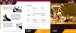
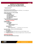
1
INSTALLATION MANUAL
P-105
AM/FM/MPX RADIO
WITH COMPACT DISC PLAYER,
CD CHANGER CONTROLS
AND QUARTZ CLOCK
INSTALLATION INSTRUCTIONS
This unit is designed for installation in GM and Chrysler cars, trucks, and vans with a 1-1/2 DIN radio opening. In some cases,
a special installation kit will be required to mount the radio to the dashboard. These kits are available at electronics supply stores
and car stereo specialty shops. Always check the kit application before purchasing to make sure the kit works with your vehicle.
If you need a kit but cannot find it available, call our toll-free “HELP” line at 1-800-645-4994.
PRE-INSTALLATION CONSIDERATIONS
IMPORTANT: Disconnect the ground cable from the negative terminal of the battery.
a. Dash Disassembly:
NOTE: Locations and types of fasteners will vary depending on the make and model of the vehicle.
Carefully check the dash for all fasteners that may require removal in order to remove the factory radio from the sub-dash.
1. Remove the screws securing the upper and/or lower portion of the dash panel.
2. Remove the screws above the instrument cluster and all screws from the trim panel that may surround the factory
radio.
3. Remove the ash tray and open the glove box to see if there are any screws that need to be removed from the dash panel.
Do not discard any screws!
NOTE: The gear shifter may need to be in low gear to allow for dash panel removal.
4. Gently unclip and remove the dash panel.
b.Removing the Factory Radio:
1. Remove any hardware securing the factory radio assembly to the sub-dash. Do not discard any hardware!
2. Disconnect the wiring and antenna cable from the factory radio.
c.Removing the Factory Radio Brackets (If Applicable):
1. Remove all nuts that secure the original factory brackets to the radio.
2. Remove and retain the original mounting brackets from the factory radio.
NOTE: Not all radios have removable mounting brackets. For GM radios with non-removable brackets, use the two enclosed.
These will satisfy most 1993 and up GM radio mounting applications. If this is not the case, it will be necessary to
purchase a special installation kit. Please consult your local car stereo installation shop or consumer electronics store.
d.Check the dashboard opening size by measuring the height and width. If the opening is not large enough,
carefully cut or file as necessary until the opening slightly exceeds the radio size. Check that there will be sufficient space
behind the dashboard for the radio chassis.
NOTE: After confirming fit, place the P-105 aside and proceed with the wiring instructions.
USING A WIRING ADAPTER
The easiest wiring method to connect the P-105 to the vehicle is to buy a wire harness adapter from your dealer, a car stereo
installation shop, or an electronics store. If you use a wiring adapter, all wires can be connected to your P-105 even before your
old radio is removed from the car.
Connecting the Wires
Splice, crimp or solder the wires from the Audiovox P-105 radio connector to the wiring adapter. Match the wires according to
the function vs. color code relationship expressed in the following table, and the wiring adapter instructions.
Attach Wires to Radio (See Figures 1 and 2.)
a. After splicing the wiring adapter to the radio connector, attach the connector to the back of the radio.
b. Attach an antenna extender cable (not supplied) and antenna adapter, if needed.
NOTE: The Dimmer function may not work in conjunction with some Chrysler vehicle models. In this case, leave the
Dimmer wire disconnected. Radio backlighting will illuminate when radio power is on.
Install Wiring Inside the Car (See Figures 1 and 2.)
a. Connect wiring adapter to the car’s existing wiring harness.
b. Connect an antenna extender cable (not supplied) to car antenna lead, if needed.
-2-
WIRING COLOR CODES
FUNCTION
COLOR
+ 12 V Acc/Ignition
Red
+ 12 V Battery/Memory
Yellow
Ground
Black
Dimmer
Orange
LF + Speaker
White
LF - Speaker
White/Black
LR + Speaker
Green
LR - Speaker
Green/Black
RF + Speaker
Gray
RF - Speaker
Gray/Black
RR + Speaker
Violet
RR - Speaker
Violet/Black
TYPICAL GM APPLICATION (See Figure 1.)
Radio Preparation:
NOTE: For GM car installations, use the GM Hardware Kit, Part Number 150-1343, which is furnished with the radio.
1. Match quickie bolt locations on the P-105 radio to the factory radio bolt locations, and snap the short quickie bolts (Item #2)
into the appropriate locations.
2. Attach the original factory brackets or those from the radio mounting kit (if required) to the P-105 radio using the supplied
flange nuts (Item #4), or use the enclosed brackets (Item #6) if the original factory brackets are not removable. Additionally,
four brass spacers bave been provided to raise the bracket height as required. Simply place the spacer on the quickie bolt
and secure the mounting bracket.
3. Some vehicle applications incorporate a rear mounting support. Remove the rubber rear bushing from the factory radio.
Match the rear quickie bolt on the P-105 radio to the rear factory radio bolt location and snap the long quickie bolt (Item #3)
into place. Thread the rubber rear bushing from the factory radio onto the P-105 long quickie bolt.
4. Plug supplied wire harness (Item #1) into the mating socket on the rear of the P-105.
Installation:
1. Connect the wiring harness from the radio to the vehicle side radio harness.
2. Plug the factory antenna cable into the antenna socket on the radio.
NOTE: GM vehicles 1992 and up will require an antenna adapter cable to convert the vehicle mini connector to a standard
connector. Antenna adapter cables are available at car stereo speciality shops.
3. If a compatible CD changer is to be used with this radio, connect the cable from the changer to the 8-pin mating socket on
the radio. If an external amplifier will be used for the rear speakers, connect the low-level output RCA leads from the radio
to the low-level inputs on the amplifier.
4. Reconnect the battery and perform a brief functional test of the radio to verify proper performance.
5. After verification, turn off the ignition switch and fasten the radio to the sub-dash using the mounting hardware previously
removed from the factory radio.
6. Re-assemble the dash using the reverse of the disassembly procedure.
-3-
-4-
P-105 WIRING HARNESS
(SUPPLIED, ITEM #1)
GM WIRING HARNESS ADAPTER
(PURCHASE SEPARATELY)
VEHICLE SIDE
RADIO HARNESS
VEHICLE DASH
SHORT
QUICKIE BOLT
ITEM #2
(supplied)
SPLICE WIRES
SHORT
QUICKIE BOLT
ITEM # 2
FLANGE NUT (2 PLACES)
ITEM #4
(2 PLACES)
LONG
QUICKIE BOLT
ITEM #3
ANTENNA
SOCKET
BRACKET
(2 PLACES)
ITEM #6
FACTORY
BRACKET
RCA CABLES
14 PIN PWR/SPKR
CONNECTOR
VEHICLE
OUTER DASH TRIM
REAR
BUSHING
FACTORY
RADIO
OR
CD CHANGER
CONNECTOR
REAR VIEW
FLANGE NUT
ITEM #4
EXISTING
MOUNTING
HARDWARE
P-105 RADIO
GM MINI- BARBLESS
ANTENNA CABLE
NOTE: GM VEHICLES 1992 AND UP
WILL REQUIRE AN ANTENNA
ADAPTER CABLE TO CONVERT
THE VEHICLE SIDE MINI
CONNECTOR TO A STANDARD
CONNECTOR
WIRING DIAGRAM-TYPICAL INSTALLATION FOR GM (Figure 1)
TYPICAL CHRYSLER APPLICATION (See Figure 2.)
Radio Preparation:
NOTE: For Chrysler car installations, use the Chrysler Hardware Kit, Part Number 150-1344, which is furnished with
the radio.
1. Select two of the four mounting tabs provided and match the radio mounting style of the vehicle as shown in Figures 3, 4 and 5.
NOTE: The tab number is stamped on the bottom of the tab.
2. Attach the mounting tabs to the radio chassis with the four small Phillips-head screws provided ( Item # 9).
3. Attach the 14-pin connector from the harness to the radio.
4. Plug the antenna cable into the antenna socket on the radio.
Installation:
1. Attach the ring lug on the ground wire (black) from the radio side harness along with the vehicle side grounding strap to the
rear of the radio chassis using the short quickie bolt (Item #2) and the flange nut (Item # 4) provided.
2. Connect the mating side of the harness to the vehicle side wiring harness.
3. Connect the vehicle antenna cable to the radio antenna connector.
4. If a compatible CD changer is to be used with this radio, connect the cable from the changer to the 8-pin mating socket on
the radio. If an external amplifier will be used for the rear speakers, connect the low-level output RCA leads from the radio
to the low-level inputs on the amplifier.
5. Reconnect the battery, and perform a brief functional test of the radio to verify proper performance.
6. After verification, turn off the ignition switch and install the radio into the sub-dash of the vehicle using either two 10mm
hex-head screws (not provided), or use the existing factory hardware.
7. Re-assemble the dash using the reverse of the disassembly procedure.
-5-
-6-
CHRYSLER APPLICATION
MOUNTING TABS
AND HARDWARE
(See Figures 3, 4 and 5)
VEHICLE SIDE
RADIO HARNESS
CHRYSLER WIRING HARNESS ADAPTER
(PURCHASED SEPARATELY)
P-105
WIRING HARNESS
VEHICLE DASH
ANTENNA
SOCKET
EXISTING
MOUNTING HARDWARE
OR 10mm SCREWS
P-105 RADIO
SPLICE WIRES
VEHICLE SIDE
GROUNDING STRAP
FLANGE NUT
ITEM #4
(supplied)
ANTENNA CABLE
RCA CABLES
14 PIN PWR/SPKR
CONNECTOR
VEHICLE
OUTER DASH TRIM
LONG QUICKIE
BOLT
ITEM #3
CD CHANGER
CONNECTOR
REAR VIEW
TYPICAL INSTALLATION FOR CHRYSLER (Figure 2)
TAB #2
TAB #1
Figure 3
TAB #2
TAB #4
Figure 4
TAB #3
TAB #2
Figure 5
-7-
© 2001 Audiovox Electronics Corp., Hauppauge, NY 11788
128-5914A