1
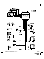
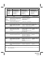
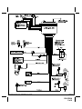
Model APS-20LAD
Installation Manual
Vehicle Alarm System
With Channel 2 Auxiliary Output
Installation Instructions
This Unit Is Intended For Installation In Vehicles With
12 Volt Negative Ground Electrical Systems Only
Kit Contents:
APS-20LAD Control Module
(2) - Two Button Transmitters
2 Channel Code Learning Receiver
(1) - Multi Pin Input/Output Harness
(1) - Two Pin Door Lock Harness
(1) - Two Pin LED Indicator
(1) - Two Pin Valet / Programming Switch
Multi-tone Siren
(1) - 2 Stage Shock Sensor
(1) - Installation Manual
(1) - Operator's Manual
(1) - Limited Warranty
(2) - Window Decals
Released 9-24-99.
Revision A: Changed diagram 4-30-03.
128-5560A
1 of 8
The APS-20LAD Vehicle Alarm System is designed to provide a basic deterrent to vehicle theft, and a convenient
electronic means to gain access to the vehicle by providing RF remote control over the vehicle's power door lock
system. The unit also includes outputs to control the vehicle's parking lights, and an additional auxiliary output
designed to allow for control over an optional device such as a power trunk release or engine starting device.
BEFORE BEGINNING THE INSTALLATION:
1) Find locations to mount the following items:
Control Module
Shock Sensor
Electronic Siren
Dash Mounted L.E.D.
Valet/Program/Manual Override Switch
2) Determine the type of factory power door lock system in use. Knowing the type of system up front
before beginning the installation can make the installation easier and faster since you can build whatever
interface (if needed) beforehand.
3) Determine whether the vehicle includes a power trunk release system, and if so what type it is.
CONTROL MODULE:
The Control Module is NOT waterproof, DO NOT mount it in the Engine Compartment. Select a mounting location
under the dashboard. Choose a mounting location that will not interfere with proper operation of the vehicle's
steering column mechanism, brake and gas pedals. Secure the Control Module in the chosen location. Wait until
all components have been installed and all connections are made before plugging in the main connectors.
SIREN:
Select a location in the engine compartment that is not accessible from below the vehicle. The selected location
must be clear of hot or moving parts within the engine compartment The siren must be pointed downward to
prevent water retention and the flared end must be pointed away from and out of the engine compartment for
maximum sound distribution. Before securing the siren, check behind your chosen location to assure that the
mounting screws will not penetrate any factory wiring or fluid lines. Secure the siren mounting bracket using #8 self
taping screws by first using the mounting bracket as a template, scribe or mark the three bracket mounting holes.
Drill the three marked holes using a 1/8" drill bit, than mount the siren using #8 sheet metal screws.
VALET/PROGRAM/MANUAL OVERRIDE SWITCH :
Since much of the use of this switch by the vehicle operator requires concurrent operation of the ignition key switch,
it is recommended that the Valet/Program/Manual Override Switch be placed such that it can be reached by the
driver's left hand, while they operate the ignition key switch with their right hand. It is also highly recommended that
this switch be concealed to provide the highest level of security. The switch can be mounted to the lower dash
panel in the driver's area. Inspect behind the chosen location to insure that adequate clearance is allowed for the
body of the switch, and also that the drill will not penetrate any existing factory wiring or fluid lines. Drill a 1/4" hole
in the desired location and mount the switch by passing it through the panel from the opposite side. Secure the
switch using the nut, star-washer, and on/off face plate. It is suggested that the switch be oriented to allow the on
position to be up toward the driver and the off position to be down or away from the driver. Route the switch’s wires
and connector toward the location of the Control Module.
DASH MOUNTED L.E.D.:
The small Red LED included in the kit serves as a visual indicator of the system's status and provides a visual
deterrent to a potential thief. The LED also provides important feed back information during the transmitter and
feature program modes. The LED should be installed in the dashboard in a highly visible area that may be seen
from the driver’s seat as well as from outside the vehicle. Try to choose a location close enough to the Control
Module so that the LED's wires will reach. Carefully inspect the area behind your chosen location to insure that the
drill will not penetrate any existing factory wiring or fluid lines. Drill a 1/4" hole and pass the connector end of the
LED through the hole, and route the wires toward the location of the Control Module. Press the LED firmly into place
until it is fully seated.
HOOD AND TRUNK PIN SWITCHES:
The pin switch included in this package is intended for protecting the hood or trunk/hatch areas of the vehicle. In all
cases, the switch must be mounted to a grounded metal surface. When the pin switch is activated, (hood/trunk
open), it will supply a ground to the input wire thus activating the alarm. Mount the switch in the hood or trunk
locations away from water drain paths. If necessary, the included bracket may be used to move the switch away
from rain gutters or allow mounting to the firewall behind the hood seal. In both cases the switch must be set up to
allow the hood or trunk door to depress the switch at least 1/4 inch when the hood or trunk is closed and fully
2
128-5560A
2 of 8
extended when the hood or trunk is opened. For direct mounting, a 1/4 inch hole must be drilled. Carefully check
behind the chosen location to insure the drill will not penetrate any existing factory wiring or fluid lines. Drill a 1/4"
hole in the desired location and thread the pin switch into it using a 7/16" nut driver or deep well socket. If using the
mounting bracket, first secure the bracket to the desired location and secure the pin switch in the pre-threaded
mounting bracket hole.
WIRING CONNECTIONS:
RED Wire (Connects to RED/WHITE wire at harness plug): Main Power Input Wire
These are the main power input wires for the APS-20LAD system. Both wires connect to a separate fuseholder
contained in the harness. These fuseholders each hold a separate ATC fuse, one 5AMP and one 15AMP. This RED
wire must be connected to a constant power wire at the vehicle's ignition switch harness or fusebox. Most vehicles
have at least one battery source wire supplying power to the ignition switch.
Locate a constant power wire or power taping point either at the vehicle's ignition switch harness or fuseblock. This
wire will read +12VDC at all times, regardless of the position of the ignition key switch. Splice and tape the RED
wire of the harness to this point.
YELLOW Wire: Ignition Input Wire
This wire provides the APS-20LAD system with an ignition power input from the vehicle. Connect this wire to the
primary ignition wire from the ignition switch. This vehicle wire will show +12VDC when the ignition key is turned to
the "ON" or "RUN" position and when turned to the "START" or CRANK" positions, and will have 0VDC when the
key is turned to the "OFF" and "ACCESSORY" positions.
Locate an ignition power wire at the vehicle's ignition switch harness. Splice and tape the YELLOW wire of the
system to this point.
WHITE Wire: Positive Parking Light Flash Wire
This wire is designed to provide a +12VDC positive light flash output, driven by the APS-20's internal relay, to be
connected directly to the vehicle's positive parking light circuit. Once the feedpoint is located, confirm that all the
vehicle's parking lights will illuminate when +12VDC is connected to it.
NOTE: Some vehicles, (mostly European) have isolated "left" and "right" side parking lights. To connect to
the parking light systems in these vehicles, you must use 2 separate SPDT or DPST relays to connect
one to each side in order to keep them isolated.
Locate a parking light feedpoint and attach the WHITE wire of the system to this point.
BROWN Wire: Negative (-) Door Trigger Input Wire
If the vehicle's interior lights are controlled by grounding door pin-switches (typical of most GM, Dodge, and import
vehicles), the Brown negative door trigger wire should connect to one of the vehicle's factory door pin switches. In
many cases the factory door pin-switches are wired in parallel, making it necessary to connect to only one door
switch in order to detect the opening of all doors. In a few cases this will not be true, making it necessary to connect
to the vehicle dome light, or isolate door trigger wires.
Locate the vehicle's negative door trigger wire in the vehicle's kick panel, under-dash or the vehicle's
pin-switch. Splice and tape the BROWN wire of the system to this point.
PURPLE Wire: Positive (+) Door Trigger Input Wire
If the vehicle's interior lights are controlled by +12VDC (Positive) door pin-switches (typical of most Ford vehicles),
the Purple positive door trigger wire should connect to one of the vehicle's factory door pin switches. In many cases
the factory door pin-switches are wired in parallel, making it necessary to connect to only one door switch in order
to detect the opening of all doors. In a few cases this will not be true, making it necessary to connect to the vehicle
dome light, or isolated door trigger wires.
Locate the vehicle's positive door trigger wire in the vehicle's kick panel or under-dash. Splice and tape the
PURPLE wire of the system to this point.
DARK GREEN Wire: Negative (-) Hood/Trunk Trigger Input Wire
This input is designed to connect to a grounding hood, trunk, or rear hatch pin-switch, to allow the system to trigger
should those entry points be violated. To provide protection for the hood, the Dark Green negative hood/trunk
trigger wire should connect to the existing factory hood pin-switch (if one exists) or to a suitable aftermarket installed hood pin-switch. To provide protection for the trunk or hatch, the Dark Green negative hood/trunk trigger
wire should connect to the existing factory trunk or hatch pin-switch wire that controls the trunk or hatch light circuit.
In cases where both hood and trunk/hatch entry points are to be connected together to the Dark Green wire, barrier
diodes must be used to prevent the flow of current from causing the under hood light to come on when the trunk/
3
128-5560A
3 of 8
hatch is opened, and vice-versa. If only the hood, or only the trunk/hatch is connected to the Dark Green wire, no
diode is needed.
Note: The diodes which may be required for certain types of installations are the common 1N4000 series type. You
may chose to use any of the diodes in this series, with the 1N4003 and 1N4007 being the most common types. The
diodes must be installed with careful regard for their direction of current flow.
Note: This wire will be shunted when remote control channel 2 is accessed, (trunk release). This wire will remain
shunted all the while there is ground present and for 5 seconds after the ground is removed. This allows the operator
to open the trunk via the remote transmitter without having to first disarm the alarm system.
WHITE/BLACK Wire: Siren Output Wire
This wire provides a positive output (3A Max.) designed to directly drive a standard electronic siren. Find a suitable
mounting location for the siren and mount it properly. Run the Red wire of the siren into the passenger compartment to the location of the APS-20LAD. Connect the White/Black wire to the Red wire from the siren. The Black
wire from the siren should then be securely grounded to the vehicle chassis.
BLACK Wire: Main System Ground
This is one of the most important wires of the APS-20LAD installation. It must be connected properly to a solid
chassis ground it will help ensure reliable system operation. Special care must be taken to locate a clean metal part
of the chassis as an attachment point for this wire. Some installers prefer to locate a sturdy metal bolt under the
dashboard or at the kick panel, and use it as the attachment point.
If you find a suitable factory bolt that reads ground when tested, attach a insulated ring terminal connector to the Black
wire, remove the bolt, place the red ring terminal over the bolt and reinstall it, tightening it securely. If you choose
instead to drill your own mounting hole into the vehicle's chassis, be certain to remove any paint or grease and
secure the ring terminal.
ORANGE Wire: Ground When Armed Output (Optional relay required.)
This wire provides a 300mA ground output when the alarm circuit is armed to control the starter inhibit relay.
Connect the Orange wire to terminal #86 of a standard SPDT relay. Connect terminal #85 of the relay to an ignition
wire in the vehicle that is +12VDC when the ignition key is turned to the on and start positions and off when the key
is in the off position. Locate and cut the low current starter solenoid wire found at the vehicle's ignition switch
harness. This wire will have +12VDC when the ignition key is moved to the start (crank) position and will have 0
volts in all other key positions.
Connect one side of the cut wire to terminal #87a of the relay. Connect the other side of the cut wire to terminal #30
of the relay.
DARK BLUE Wire: Delayed 300mA Pulsed, Channel 2 Output
The Dark Blue wire supplies a 300mA ground pulsed output whenever channel two of the receiver is accessed.
Pressing the transmitter Option button for three seconds will access Channel 2. This is a low current output and
must be connected to a relay to supply power to the trunk release or the circuit you wish to control. Connect the
Dark Blue wire to terminal # 86 of a VF45F11 P&B relay or equivalent. Connect terminal # 85 of the relay to a fused
+12VDC source. Connect the common, normally open, and normally closed contacts of the relay to perform the
selected function of Channel 2.
DOOR LOCK/UNLOCK CONTROL HARNESS (+) and (-)
2-PIN White Plug w/2 Wires; RED & GREEN
The Red and Green Door Lock/Unlock output wires provide either a momentary pulsed ground (-) or a momentary
pulsed 12VDC (+) output for controlling a vehicle's power door lock/unlock circuit. In order to accomplish this "dual
polarity" output scheme these two wires produce the opposite polarity at the opposite time. To better understand
this, refer to the table below:
The output of these wires has a maximum switching capability of 300mA. Many vehicles today have factory door
lock relays which can be connected directly to these outputs, however always confirm that the factory relays in your
particular vehicle do not exceed the rated 300mA output of the units door lock/unlock circuit. Plug the two pin
connector of the door lock/unlock harness into the mating connector shell of the control module. Determine the
door lock circuit of the vehicle you are working on and wire according to the diagrams shown.
WIRING FOR "GROUND PULSE" DOOR LOCK CIRCUITS:
This is a system commonly used on most import vehicle's factory door lock/unlock systems, and with a few domestic vehicles which employ factory "keyless entry" systems. In this application, the Red wire serves as the "Lock"
output, providing a ground pulse during the arming sequence, and the Green wire serves as the "Unlock" output,
4
128-5560A
4 of 8
Wire Color
Red
Red
Green
Green
Function
Lock
Unlock
Lock
Unlock
Polarity
Ground (-)
Positive (+)
Positive (+)
Ground (-)
providing a ground pulse during the disarming sequence.
Connect the Red wire to the low current ground factory door "Lock" signal wire leading from the factory switch to the
factory door lock relay. Connect the Green wire to the low current ground factory door "Unlock" signal wire leading
from the factory switch to the factory door unlock relay.
WIRING FOR "POSITIVE PULSE" DOOR LOCK CIRCUITS:
This is a system commonly used on many domestic vehicle's factory door lock/unlock systems, particularly General
Motors and Chrysler, although not on all models. (Please see the note regarding "5-Wire Reverse Polarity Door
Lock Systems"). In this application, the Green wire serves as the "Lock" output, providing a positive pulse during the
arming sequence, and the Red wire serves as the "Unlock" output, providing a positive pulse during the disarming
sequence.
Connect the Green wire to the low current positive (+12VDC) factory door "Lock" signal wire leading from the factory
switch to the factory door lock relay. Connect the Red wire to the low current positive (+12VDC) factory door
"Unlock" signal wire leading from the factory switch to the factory door unlock relay.
4 WIRE POLARITY REVERSAL and 5 WIRE ALTERNATING DOOR LOCK CONTROL CIRCUITS:
In these applications, the AS-9159 Door Lock Interface (or equivalent 30 Amp. automotive type relays) must be used.
Refer to the Audiovox Door Lock Wiring Supplement for proper connection to these types of circuits.
PLUG-IN CONNECTIONS AND COMPLETING THE INSTALLATION:
Now that all the other components have been installed, and most of the main connections completed, it is time to
finish connecting the remaining plug-in components and completing the installation. Even though these are plug-in
connections, and the plugs have been shaped such that they cannot be plugged in wrong, please read and follow
the instructions below for each connection to make certain each component is properly installed.
DASH MOUNTED LED
2-PIN White Plug w/2 Wires; Red & Blue
The Red & Blue wires in the 2-PIN mini white connector control the anode and cathode of the dash mounted LED.
Route the twin lead Red and Blue wires from the LED to the control unit and plug the two pin connector into the
mating white mini connector shell of the control module. Do not force the connector, it will only plug in one way.
SHOCK SENSOR
Mounting The Shock Sensor
Never mount the sensor outside the vehicle where it will be exposed to the elements. Never mount any component
near hot or moving parts. Always mount the components and route the wiring away from the rotating steering shaft
assembly. Always mount the sensor within 22" of the alarm module to assure the plug in cable reaches the sensor.
1. Select a solid mounting location inside the vehicle. Ideally the inside firewall, center of the vehicle is best for
sensitivity. An alternate location can be the "A" pillar, "B" pillar, or suspended from an existing brace or wiring
harness.
2. Mount the sensor using the two screws provided or cable ties securing it to your chosen location.
Connecting The Sensor:
1. Connect the large 4 pin connector of the wiring harness to the 4 pin mating connector on the Shock Sensor.
2. Route the small 4 pin connector of the harness toward the alarm control module and connect to the mating 4 pin
connector on the alarm unit.
VALET/PROGRAM/MANUAL OVERRIDE SWITCH
2-PIN Blue Plug w/2 Wires; Black & Gray
The Black & Gray wires in the 2-PIN blue connector are the ground supply and Valet/Program input of the
APS-20LAD unit. When the Gray wire is grounded, under certain conditions, the unit will enter the valet mode.
When the Gray wire is sequentially grounded under other conditions, the unit will enter the various program modes.
Route the Black and Grey wires from the Valet/Program/Manual Override switch to the APS-20LAD unit and plug the
blue 2-PIN connector into the mating blue connector shell of the APS-20LAD control module. Do not force the
5
128-5560A
5 of 8
connector, it will only plug in one way. Note: Please refer to the section; "Programming System Features" shown
later in this installation guide to learn the operation of the valet/program/manual override switch.
POWER DOOR LOCK HARNESS
2-PIN White Plug w/2 Wires; Red & Green
The connection of the power door lock/unlock wires has already been explained. Route the Red and Green wires
to the APS-20LAD unit and plug the white 2-PIN connector into the mating white two pin connector shell of the
APS-20LAD control module. Do not force the connector, it will only plug in one way.
TRANSMITTER PROGRAMMING:
The transmitters supplied with the APS-20LAD are pre-programmed at the factory to provide the following function:
Arm/Disarm, pressed and released quickly
=
Arm/Disarm (Lock & Unlock) w/Siren Chirps
Arm/Disarm, pressed for ~ 1 second
=
Arm/Disarm (Lock & Unlock) w/o Siren Chirps
Arm/Disarm, pressed for ~ 3 seconds
=
Engage/Disengage Panic Mode
Option, pressed for ~ 3 seconds
=
Channel 2 Output
If you desire to have the transmitters operate differently from this factory configuration, please refer to the separate
Transmitter Programming Guide that came with the APS-20LAD system.
PROGRAMMING FEATURES:
There are five (5) Programmable Features on the APS-20LAD system. Study the list below, keeping in mind the
features and their defaults, (how it comes programmed from the factory), and decide how best to program the
APS-20LAD for your particular installation.
Programmable Features:
Features
First
Second
Third
Fourth
Fifth
1 Chirp
Passive Arming
Ignition D/L ON
Ignition D/UL ON
Passive D/L
Chirps ON
2 Chirp
Active Arming
Ignition D/L OFF
Ignition D/UL OFF
Active D/L
Chirps OFF
Default
Passive Arming
Ignition D/L OFF
Ignition D/UL OFF
Active D/L
Chirps ON
To Program These Features:
Entering the Programming Mode involves operating the Ignition Switch and the Valet/Program/Manual Override Switch
in a particular sequence. This sequence is very time dependent, in other words it must be performed quickly in order
for you to enter the mode. This sequence is also only one step different from the Transmitter Programming Mode,
so make certain you perform the sequence properly.
Upon entering the Programming Mode, the system is immediately set to allow adjustment of the First Programmable Feature. That First feature, "Passive or Active Arming", can then be set ON or OFF by pressing arm/
disarm of the transmitter. The system confirms that it is set to adjust the First feature by repeatedly flashing the LED
once, with a pause in between each flash. The system will then report how the feature has been set by the number
of chirps heard after pressing the transmitter button. Toggling the Valet/Program/Manual Override Switch once
again will advance you to the Second Programmable Feature, confirmed by a repeating two LED flashes, with a
pause in between each flash, etc., etc.
It is important to note that when you first enter the Programming Mode, you are automatically positioned to adjust the
First Programmable Feature, and that the Valet/Program/Manual Override Switch allows you to toggle from there
through each of the four more programmable features. However, it will not allow you to return to any feature once
you have toggled past it. Should you accidentally toggle past the feature you wanted to program, you must exit and
re-enter the Programming Mode and then adjust the feature you missed.
It is also important to note that you may toggle past as many programmable features as you wish without having to
adjust them. Each time you toggle forward to a new feature, the siren will chirp the appropriate number of times (1
or 2 times) to indicate how that feature is currently set, and the LED will flash the appropriate number of times to
indicate the number of the feature (First through Fifth) that you are set to adjust. For example, you might enter the
mode and toggle the Valet/Program/Manual Override Switch 3 times in order to adjust the Fourth programmable
feature. The system would respond with 1 Chirp, and the LED would begin to flash 4 Flashes, pause, and repeat.
This has told you that the system is ready for you to adjust the Fourth programmable feature, and that it is currently
programmed for Chirps ON. A single press of the arm/disarm button of the transmitter will cause the system
6
128-5560A
6 of 8
to produce 2 Chirps. This signifies that you have changed the programming to Chirps OFF. Please follow the
programming procedure carefully, and refer to the list of the Programmable Features above when programming the
APS-20LAD.
FEATURE
ACTION TO PERFORM
RESPONSE FROM SYSTEM
LED FLASH PATTERN
To
Enter
The
Programming
Mode
Turn the Ignition Switch ON
LED Turns OFF
Toggle the Valet/Program/Manual Override Switch
ON then OFF 3 Times
1 Siren/Horn Chirp & 1 LED Flash
Within 3 seconds,
turn the Ignition Switch OFF, then ON
1 Short Chirp, and 1 Long Chirp
You have now engaged the Programming Mode, and are set to adjust the First feature
This mode will time out automatically in 15 seconds, or can be cancelled by turning the Ignition Switch OFF
First
Press Arm/Disarm Button to Adjust Feature
1 Chirp = Passive Arming ON
1 Flash, Pause, Repeat
2 Chirps = Active Arming ON
OR Toggle the Valet/Program/Manual Override Switch once to Advance to the next feature
Second
Press Arm/Disarm Button to Adjust Feature
1 Chirp = Ign Locking ON
2 Flashes, Pause, Repeat
2 Chirps = Ign Locking OFF
OR Toggle the Valet/Program/Manual Override Switch once to Advance to the next feature
Third
Press Arm/Disarm Button to Adjust Feature
1 Chirp = Ign Unlocking ON
3 Flashes, Pause, Repeat
2 Chirps = Ign Unlocking OFF
OR Toggle the Valet/Program/Manual Override Switch once to Advance to the next feature
Fourth
Press Arm/Disarm Button to Adjust Feature
1 Chirp = Passive Doorlock ON
4 Flashes, Pause, Repeat
2 Chirps = Passive Doorlock OFF
OR Toggle the Valet/Program/Manual Override Switch once to Advance to the next feature
Fifth
Press Transmitter Button 1 to Adjust Feature
1 Chirp = Chirps ON
5 Flashes, Pause, Repeat
2 Chirps = Chirps OFF
OR Turn the Ignition Switch OFF to exit the Programming Mode
NOTE: If you accidentally toggled past the feature you intended to adjust, you must exit and re-enter the mode.
COMPLETING THE INSTALLATION:
After you have confirmed the operation of the APS-20LAD, and tested any and all optional features of the system:
1. Mount the control module up and behind the dash securing it in place with cable ties or screws. Be certain
that the chosen mounting location will not inhibit any of the controls of the vehicle.
2. Securely harness and tie all wiring up and away from all hot and moving parts that they may come in contact
with under the dash board or in the engine compartment areas.
CAUTION: Particularly avoid the area around the steering shaft and column, as wires can wrap around these
mechanisms and impair the safe operation of the vehicle.
3. Shock Sensor Sensitivity Adjusting:
Note: The shock sensor's LED's will not operate unless the alarm system is armed.
The sensitivity of the pre-detect stage, (Indicated by the Green LED), and full trigger stage, (Indicated by the Red
LED) are set with one setting. The pre-detect stage will operate at a 30% force of the full trigger stage.
a. Arm your alarm system than firmly strike the windshield pillar with the open palm of the hand considering the
force required to break the vehicle glass. If the alarm system triggers easily, disarm your alarm, turn the adjustment
screw located on the sensor counterclockwise to decrease the units sensitivity, and repeat the above test. If the
siren emitted a few short bursts (pre-detect) no further adjustment is necessary.
b. If the unit failed to pre-detect, increase the sensitivity setting by turning the adjustment potentiometer clockwise.
Note: Proper sensitivity level is dependent mostly upon technician preference, mounting location, and vehicle size.
Always consider the effect of setting the sensitivity level too high. This will cause false triggers due to environment
noise and passing vehicle vibrations. Keeping your settings at a minimum will prevent these problems.
4. Check the vehicle's wipers, lights, horn, etc... to insure proper operation.
5. Replace all panels that were removed during installation, and retest the system.
6. Explain the operation of the system and its various features to the end user if available, and place the Owner's
Manual on the dashboard for them to find and review.
7
128-5560A
7 of 8
© 2003 Audiovox Corp., Hauppauge, NY 11788
128-5560A
128-5560A
8 of 8
Modelo APS-20LAD
Manual de instalación
Sistema de alarma para vehículo con salida
auxiliar por canal 2
Instrucciones de instalación
Esta unidad se puede instalar en vehículos con sistemas eléctricos con
conexión a tierra negativa de 12 voltios solamente
Contenido del kit:
Módulo de control APS-20LAD
(2) - Transmisores de llavero con dos botones
Receptor con captación de código de 2 canales
(1) - Arnés de cableado de entrada / salida con múltiples clavijas
(1) - Arnés de trabado de puertas con dos clavijas
(1) - Indicador LED con dos clavijas
(1) - Interruptor valet / programación con dos clavijas
Sirena de varios tonos
(1) - Detector de choque de 2 etapas
(1) - Manual de instalación
(1) - Manual para el operador
(1) - Garantía limitada
(2) - Calcomanías para las ventanillas
Released 9-24-99.
128-5560A
1 of 8
El sistema de alarma para vehículos APS-20LAD está destinado a brindar un elemento de disuasión contra robo de vehículos y
un medio electrónico conveniente de tener acceso al vehículo mediante un control remoto de RF para el sistema eléctrico de
trabado de las puertas del vehículo. La unidad incluye también salidas para controlar las luces de estacionamiento del vehículo
y otra salida auxiliar para permitir controlar algún dispositivo opcional como por ejemplo el desenganche eléctrico de la tapa del
baúl o el dispositivo de arranque del motor.
ANTES DE INICIAR LA INSTALACIÓN:
1. Ubique los lugares donde instalará los siguientes elementos:
Módulo de control
Detector de choque
Sirena electrónica
Indicador L.E.D. montado en el tablero
Interruptor valet / programación / captura manual
2. Determine el tipo de sistema eléctrico de trabado de las puertas que viene instalado de fábrica. Si se sabe cuál es el tipo de
sistema antes de empezar con la instalación se facilitará y acelerará la misma, dado que puede crear la interfaz que se
necesite de antemano.
3. Determine si el vehículo incluye un sistema de desenganche eléctrico del baúl, y de ser así, de qué tipo es.
MÓDULO DE CONTROL:
El módulo de control NO es impermeable, NO lo monte en el compartimento del motor. Elija un lugar de montaje debajo del
tablero de instrumentos. El lugar de montaje no deberá interferir con la operación adecuada del eje o de la columna de la
dirección y de los pedales de freno y acelerado del vehículo. Asegure el módulo en el lugar elegido. Espere a que todos los
componentes estén instalados y todas las conexiones hechas antes de enchufar los conectores principales.
SIRENA:
Elija un lugar en el compartimento del motor que no sea accesible desde abajo del vehículo. El lugar elegido debe estar alejado
o separado de las piezas calientes o móviles que hay en el compartimento del motor. La sirena tiene que estar apuntando hacia
abajo para evitar la retención de agua y el extremo ancho debe apuntar hacia afuera del compartimento del motor para lograr
una máxima distribución del sonido. Antes de fijar la sirena, fíjese detrás del lugar elegido para asegurarse de que los tornillos
de montajes no penetren en ningún cable o conducto de líquidos o fluidos que ya venga instalado de fábrica. Sujete el soporte
de montaje de la sirena con tornillos #8, usando primero el soporte de montaje como plantilla, marque los tres orificios para el
soporte de montaje. Perfore los tres orificios marcados con una mecha de taladro de 1/8 pulgadas y luego coloque la sirena
usando tornillos de metal #8.
INTERRUPTOR VALET / PROGRAMACIÓN / CAPTURA MANUAL:
Dado que gran parte del uso de este interruptor por parte del conductor del vehículo requiere la operación conjunta con la llave
de encendido, se recomienda que el montaje del interruptor valet / programación / captura manual sea en un lugar que el
conductor tenga fácil acceso con la mano izquierda, mientras opera la llave de encendido con la mano derecha. También se
recomienda ocultar el interruptor para tener un mayor nivel de seguridad. Se puede montar el interruptor en el panel inferior del
tablero en el área del conductor. Asegúrese de fijarse detrás del tablero para comprobar si hay suficiente espacio para la caja
del interruptor y para confirmar que el taladro no vaya a dañar ningún cable o conducto para líquidos o fluidos que ya venga
instalado de fábrica. Perfore un orificio de ¼ pulgadas en el lugar deseado e instale el interruptor pasándolo por el panel desde
el lado opuesto. Fije el interruptor con una tuerca, una arandela estrella y una placa con la inscripción “on/off”. Se sugiere que
el interruptor quede colocado de manera tal que la posición “on” (encendido) esté hacia arriba o hacia el conductor y la posición
“off” (apagado) hacia abajo o más lejos del conductor. Dirija los cables y el conector del interruptor hacia el módulo de control.
INDICADOR L.E.D. MONTADO EN EL TABLERO DE INSTRUMENTOS:
El pequeño indicador LED rojo que viene en el kit sirve como indicador visual del estado de la alarma y proporciona una
elemento de disuasión visual para un posible ladrón. El indicador LED proporciona también información importante durante los
modos de programación del transmisor y de las funciones. Se debe instalar el LED en el tablero de instrumentos, en un lugar
que sea bien visible para que se pueda ver fácilmente desde el asiento del conductor así como desde afuera del vehículo. Elija
un lugar de montaje cercano al módulo de control para que los cables del LED puedan alcanzarlo. Fíjese bien detrás del lugar
elegido para asegurarse de que el taladro no penetre ningún cable o conducto para líquidos o fluidos que ya venga instalado de
fábrica. Perfore un orificio de ¼ pulgada en el lugar deseado y pase el extremo del conector del LED por el orificio y hacia el
módulo de control. Apriete con firmeza el LED hasta que quede bien asentado en el lugar de montaje.
INTERRUPTORES DE CLAVIJA PARA EL CAPÓ Y BAÚL:
Los interruptores de clavija que se incluyen en este paquete tienen por objeto proteger el capó y el baúl del vehículo. En todos
los casos, se debe montar el interruptor en una superficie metálica conectada a tierra. Cuando se activa el interruptor de clavija
(se abre el capó / baúl), proporcionará una conexión a tierra al cable de entrada que activa la alarma. Instale los interruptores en
el capó y el baúl lejos de los desagües de agua. Si es necesario, se puede usar los soportes provistos para mover al interruptor
lejos de las canaletas de agua o permitir el montaje en el muro contrafuego detrás del sellante del capó. En ambos casos, se
debe colocar el interruptor como para permitir que el capó o la puerta del baúl oprima el interruptor ¼ de pulgada, por lo menos,
al cerrar el capó o el baúl y que quede totalmente extendido cuando se abre el capó o el baúl. Para un montaje directo, se debe
perforar un orificio de ¼ pulgada. Fíjese bien detrás del lugar elegido para asegurarse de que el taladro no penetre ningún cable
o conducto para líquido que ya venga instalado de fábrica.
Perfore un orificio de ¼ pulgada en el lugar deseado y coloque el interruptor de clavija usando una llave para tuercas de 7/16
pulgada o un encastre profundo. Si usa el soporte de montaje, coloque primero el soporte en el lugar deseado e instale el
interruptor de clavija en el orificio del soporte de montaje roscado.
CONEXIONES DE CABLEADO:
Cable ROJO (conecta el cable ROJO Y BLANCO con el enchufe del arnés): Cable de entrada eléctrica principal
Estos son los cables de entrada eléctrica principal del sistema APS-20LAD. Ambos cables se conectan a un portafusible
2
128-5560A
2 of 8
diferente en el arnés. Cada uno de estos portafusibles sostiene un fusible ATC, uno de 5A y otro de 15A. Este cable ROJO debe
ser conectado a un cable de energía constante del arnés o de la caja de fusibles del interruptor de encendido del vehículo. La
mayoría de los vehículos tiene por lo menos un cable proveniente de la batería que suministra energía eléctrica al interruptor de
encendido.
Ubique un cable de alimentación eléctrica constante o un punto de bifurcación en el arnés o en la caja de fusibles del interruptor
de encendido del vehículo. Este cable tendrá una lectura constante de +12 V CC, independientemente de la posición de la llave
de encendido. Empalme y adhiera el cable ROJO del arnés a este punto.
Cable AMARILLO: Cable de entrada de encendido
Este cable suministra al sistema APS-20LAD la entrada de energía eléctrica de encendido proveniente del vehículo. Conecte
este cable al cable primario de encendido del interruptor de encendido. Este cable tendrá +12 V CC cuando la llave de contacto
se coloca en las posiciones "ON" o "RUN" (encendido) y "START" o "CRANK" (arranque), y 0 V CC cuando la llave de contacto
esté en las posiciones "OFF" (apagado) y "ACCESSORY" (accesorios).
Ubique un cable de energía de encendido en el arnés del interruptor de encendido del vehículo. Empalme y adhiera el cable
AMARILLO del sistema a este punto.
Cable BLANCO: Cable positivo del destellador de las luces de estacionamiento
Este cable tiene el propósito de suministrar una salida positiva de +12 V CC al destellador de las luces de estacionamiento,
conducidos por el relé interno de APS-20, que se conectará directamente al circuito positivo de las luces de estacionamiento del
vehículo.
Una vez que se localiza el punto de alimentación, confirme que todas las luces de estacionamiento del vehículo se iluminarán
cuando estén conectadas a +12 V CC.
NOTA: Algunos vehículos (en su mayoría los europeos) tienen dos lados separados de luces de estacionamiento, uno derecho
y otro izquierdo. Para conectar el sistema de luces de estacionamiento en estos vehículos debe usar 2 relés SPDT o
DPST para conectar cada uno de los lados y mantenerlos separados.
Ubique un punto de alimentación de las luces de estacionamiento y conecte el cable BLANCO del sistema a este punto.
Cable MARRÓN: Cable de entrada negativa (-) de activación de puertas
Si las luces interiores del vehículo están controladas por interruptores de clavija a tierra de las puertas (la mayoría de los
automóviles GM, Dodge e importados), se debe conectar el cable marrón de entrada negativa a uno de los interruptores de
clavija de la puerta del vehículo. En la mayoría de los casos, tendrá que conectar solamente a un interruptor de puerta,
independientemente de cuántas puertas tenga el vehículo, ya que la mayoría de los circuitos de iluminación de puertas están
conectados en paralelo. En los pocos casos que no es así, es necesario conectar a la luz del techo o a cada cable del
interruptor de puerta por separado.
Ubique el cable negativo del interruptor de puertas del vehículo en el panel inferior, debajo del tablero de instrumentos o en el
conmutador de clavija del vehículo. Empalme y adhiera el cable MARRÓN del sistema a este punto.
Cable VIOLETA: Cable de entrada positiva (+) de activación de puertas
Si las luces interiores del vehículo están controladas por interruptores de clavija +12 V CC (positivos) de las puertas (la mayoría
de los automóviles Ford), se debe conectar el cable violeta de entrada positiva a uno de los interruptores de clavija de la puerta
del vehículo. En la mayoría de los casos, tendrá que conectar solamente a un interruptor de puerta, independientemente de
cuántas puertas tenga el vehículo, ya que la mayoría de los circuitos de iluminación de puertas están conectados en paralelo.
En los pocos casos que no es así, es necesario conectar a la luz del techo o a cada cable del interruptor de puerta por separado.
Ubique el cable positivo del interruptor de puertas del vehículo en el panel inferior, debajo del tablero de instrumentos o en el
interruptor de clavija del vehículo. Empalme y adhiera el cable VIOLETA del sistema a este punto.
Cable VERDE OSCURO: Cable de entrada negativa (-) de activación del capó / baúl
Esta entrada tiene el propósito de conectar al interruptor de clavija a tierra del capó, del baúl o de la puerta trasera, para permitir
disparar el sistema cuando uno de estos lugares de acceso ha sido violado. En el capó, debe conectar este cable negativo al
interruptor de clavija que viene instalado de fábrica del capó (si tiene) o a un interruptor de clavija instalado posteriormente. En
el baúl o la puerta trasera debe conectarlo al interruptor de clavija que viene instalado de fábrica del baúl o de la puerta trasera
que controla el circuito de luces del baúl o puerta trasera.
En los casos donde tanto el punto de entrada del capó como del baúl o puerta trasera se conectan con el cable verde oscuro,
se deben usar diodos de aislamiento para prevenir el flujo de corriente que encendería la luz interior del capó cuando se abre
el baúl o puerta trasera, y viceversa. Si se conecta sólo el capó, o el baúl / puerta trasera al cable verde oscuro, el diodo no es
necesario.
Nota: Los diodos que pueden ser necesarios para algunas instalaciones son los comunes de la serie 1N4000. Puede usar
cualquiera de los diodos de esta serie, siendo los tipos 1N4003 y 1N4007 los más comunes. Los diodos deben ser
instalados cuidadosamente teniendo en cuenta las direcciones del flujo de corriente.
Nota: Este cable se derivará cuando se acceda al canal 2 del control remoto (desenganche del baúl). Este cable quedará derivado
mientras haya una conexión a tierra y durante 5 segundos después de que se quite la conexión a tierra. Esto permite al
operador abrir el baúl por medio de un transmisor remoto sin tener que desactivar primero el sistema de la alarma.
Cable BLANCO Y NEGRO: Cable de salida de la sirena
Este cable suministra una salida positiva (máximo 3A) en forma directa a una sirena electrónica estándar. Busque un lugar
apropiado para la sirena y móntela correctamente. Pase el cable rojo de la sirena del compartimento de pasajero al APS-20LAD.
Conecte el cable blanco y negro con el rojo de la sirena. Fije el cable negro de la sirena a una conexión a tierra del chasis.
3
128-5560A
3 of 8
Cable NEGRO: Sistema principal de conexión a tierra
Este es uno de los cables más importantes de la instalación del sistema APS-20LAD. Debe conectarse correctamente a una
parte sólida del chasis para asegurar el funcionamiento seguro del sistema. Elija cuidadosamente una parte metálica limpia y
sólida del chasis como punto de conexión para este cable. Algunos instaladores prefieren como punto de conexión un tornillo
firme de metal del panel inferior o debajo del panel de instrumentos.
Si encuentra un tornillo apropiado que indica una conexión a tierra cuando lo prueba, coloque un conector terminal de aro
aislado al cable negro, saque el tornillo, coloque el terminal de aro rojo sobre el tornillo, y vuelva a colocarlo, ajustándolo bien.
Si prefiere perforar un orificio de montaje en el chasis, asegúrese de quitar toda pintura o grasa que haya y fije el terminal de aro.
Cable anaranjado: Salida de conexión a tierra cuando está activado
Este cable proporciona una salida de conexión a tierra de 300 mA cuando se activa el circuito de alarma para controlar el relé
de bloqueo del arrancador. Conecte el cable anaranjado al terminal 86 del relé SPDT estándar. Conecte el terminal 85 del relé
a un cable de encendido del vehículo que sea +12 V CC cuando el interruptor de encendido pase a las posiciones “on” (encendido)
y “start” (arranque) y “off” (apagado) cuando la llave esté en “off”. Ubique y corte el cable de solenoide de arranque de poca
corriente que se encuentra en el arnés del interruptor de encendido del vehículo. Este cable tendrá +12 V CC cuando se mueva
la llave de contacto a la posición de arranque (start) y tendrá 0 voltios en todas las otras posiciones de la llave.
Conecte un lado del cable cortado al terminal 87a del relé. Conecte el otro lado del cable cortado al terminal 30 del relé.
Cable azul oscuro: Salida con impulsos y demorada del canal 2 de 300 mA
El cable azul oscuro proporciona una salida a tierra con impulsos de 300 mA cuando se accede al canal dos del receptor. Al
oprimir el botón de opciones del transmisor durante tres segundos, se accederá al canal dos. Se trata de una salida de baja
corriente y debe conectarse a un relé para alimentar al desenganche del baúl o el circuito que desee controlar. Conecte el cable
azul oscuro al terminal 86 de un relé VF45F11 P&B o equivalente. Conecte el terminal 85 del relé a una fuente de +12 V CC con
fusibles. Conecte los contactos comunes, normalmente abiertos y normalmente cerrados del relé para realizar la función elegida
del canal 2.
Arnés (+) y (-) para trabaR / destrabar puertas
Enchufe blanco de 2 CLAVIJAS con 2 cables; ROJO Y VERDE
Los cables de salida para trabar / destrabar puertas de color rojo y verde proporcionan o bien un impulso momentáneo con
conexión a tierra (-), o uno también momentáneo de +12 V CC (+) para controlar los circuitos para trabar / destrabar las puertas
del vehículo. Para obtener esta combinación de salida de “polaridad doble” ambos cables producen la polaridad opuesta a
tiempos opuestos. Para entender mejor este concepto, consulte la tabla siguiente:
La salida de estos cables tiene una capacidad máxima de conmutación de 300 mA. Actualmente, muchos vehículos tienen relés
para trabar las puertas que pueden conectarse directamente a estas salidas, sin embargo, confirme siempre que los relés del
vehículo que vienen instalados de fábrica no excedan la salida nominal de 300 mA de los circuitos para trabar / destrabar
puertas de la unidad. Enchufe el conector de dos clavijas del arnés para trabar / destrabar puertas en el correspondiente
conector del módulo de control. Determine cómo es el circuito para trabar puertas del vehículo en el que se encuentra trabajando
y tienda los cables de acuerdo con los diagramas que se ilustran.
CABLEADO PARA CIRCUITOS PARA TRABAR PUERTAS “IMPULSO A TIERRA”:
La mayoría de los sistemas que comúnmente vienen instalados de fábrica para trabar / destrabar puertas de vehículos importados
y algunos nacionales de “entrada sin llave” emplean este sistema. En esta aplicación, el cable rojo proporciona un impulso a
tierra durante la secuencia de activación o una salida a tierra con impulsos para trabar puertas, el cable verde proporciona un
impulso a tierra durante la secuencia de desactivación o una salida a tierra con impulsos para destrabar puertas.
Color del cable
Rojo
Función
Polaridad
Trabar
A tierra (-)
Rojo
Destrabar
Positiva (+)
Verde
Trabar
Positiva (+)
Verde
Destrabar
A tierra (-)
Conecte el cable rojo al cable de señal a tierra de baja corriente del interruptor para trabar las puertas que viene instalado de
fábrica al relé para trabar puertas de fábrica. Conecte el cable verde al cable de señal a tierra de baja corriente del interruptor
para destrabar las puertas que viene instalado de fábrica al relé para destrabar puertas de fábrica.
CABLEADO PARA CIRCUITOS PARA TRABAR PUERTAS “IMPULSO POSITIVO”:
La mayoría de los sistemas que comúnmente vienen instalados de fábrica para trabar / destrabar puertas de vehículos nacionales
emplea este sistema, sobretodo General Motors y Chrysler, aunque no en todos los modelos. En esta aplicación, el cable verde
proporciona una salida de impulso positivo durante la secuencia de activación para trabar puertas, y el cable rojo proporciona
una salida de impulso positivo durante la secuencia de desactivación para destrabar puertas.
Conecte el cable verde al cable de señal positiva de baja corriente (+12 V CC) del interruptor para trabar las puertas que viene
instalado de fábrica al relé para trabar puertas de fábrica. Conecte el cable rojo al cable de señal positiva de baja corriente (+12
V CC) del interruptor para destrabar las puertas que viene instalado de fábrica al relé para destrabar puertas de fábrica.
2
128-5560A
4 of 8
CIRCUITOS DE CONTROL DE TRABADO DE PUERTAS DE INVERSIÓN DE POLARIDAD DE 4 CABLES y ALTERNADO
DE 5 CABLES:
En estas aplicaciones, se debe usar la interfaz de trabado de puertas AS-9159 (o relés para automóviles de 30 A equivalentes).
Consulte del Suplemento de Cableado para trabado de puertas de Audiovox para obtener información sobre el cableado correcto
de estos circuitos.
CONEXIONES QUE SE ENCHUFAN Y FINALIZACIÓN DE LA INSTALACIÓN:
Ahora que todos los otros componentes han sido instalados y completada la mayoría de las conexiones principales, es el
momento de terminar de conectar los componentes enchufables que restan y finalizar la instalación. Aun cuando estos conexiones
se enchufan, y la forma de los enchufes no permite que se coloquen en forma equivocada, lea las siguientes instrucciones para
cada conexión para asegurarse que cada componente es instalado correctamente.
INDICADOR L.E.D.
MONTADO EN EL TABLERO DE INSTRUMENTOS:
Enchufe blancos de 2 CLAVIJAS con 2 cables; rojo y azul
Los cables rojo y azul del miniconector blanco de 2 clavijas controlan el ánodo y cátodo del indicador LED montado en el tablero.
Pase los cables rojo y azul del LED a la unidad de control de arranque remoto y enchufe el conector de dos clavijas en el
miniconector blanco correspondiente del módulo de control. El conector se puede enchufar de una sola manera, no lo fuerce.
DETECTOR DE CHOQUE
Montaje del detector de choque
Nunca instale el detector de choque fuera de vehículo donde estará expuesto a los elementos. No instale ningún componente
cerca de piezas calientes o móviles. Siempre monte los componentes y pase el cableado lejos del eje/la columna de la dirección.
Siempre monte el detector a menos de 22 pulgadas del módulo de alarma para asegurarse que el cable y enchufe llegan al
detector.
1. Elija un lugar de montaje sólido en el interior del vehículo. El lugar ideal es el muro contrafuego, en el centro del vehículo.
Otras alternativas son la columna “A”, columna “B” o suspendido de un puntal o arnés de cableado existente.
2. Monte el detector usando los dos tornillos que se proveen o átelo con cables.
Conexión del detector:
1. Conecte el conector grande de 4 clavijas del arnés de cableado con el conector complementario de 4 clavijas en el detector
de choque.
2. Pase el conector pequeño de 4 clavijas del arnés hacia el módulo de control de la alarma y conecte con el conector complementario
de 4 clavijas en la unidad de alarma.
Interruptor valet / programación / captura manual
Enchufe azul de 2 CLAVIJAS con 2 cables; negro y gris
Los cables negro y gris del conector azul de dos clavijas representan la alimentación de conexión a tierra y la entrada programación
/ valet de la unidad APS-20LAD. Cuando el cable gris está conectado a tierra, en ciertas condiciones, la unidad entrará en el
modo valet. Cuando el cable gris está conectado a tierra en otras condiciones, la unidad entrará en los diversos modos de
programación. Pase los cables negro y gris del interruptor valet / programación / captura manual a la unidad APS-20LAD y
enchufe el conector de dos clavijas en el correspondiente conector azul del módulo de control. El conector se puede enchufar
de una sola manera, no lo fuerce.
Nota: Consulte la sección Programación de las funciones del sistema que aparece más adelante en esta guía de instalación
para obtener información sobre el funcionamiento y uso del interruptor valet / programación.
Arnés para EL trabaDO ELÉCTRICO DE puertas
Enchufe blanco de 2 CLAVIJAS con 2 cables; rojo y verde
Ya se ha explicado la conexión de los cables para el trabado o destrabado eléctrico de las puertas. Pase los cables rojo y verde
hacia la unidad APS-20LAD y enchufe el conector blanco de 2 clavijas en el correspondiente conector blanco de dos clavijas del
módulo de control del APS-20LAD. No fuerce el conector dado que se puede enchufar de una sola manera.
PROGRAMACIÓN DEL TRASNMISOR:
Los transmisores provistos con el sistema APS-20LAD vienen preprogramados de fábrica para realizar las siguientes funciones:
Activar / Desactivar, se oprime y suelta rápidamente
= Activar / Desactivar (Trabar y destrabar) con chirridos de la sirena
Activar / Desactivar, se oprime durante ~ 1 segundo
= Activar / Desactivar (Trabar y destrabar) sin chirridos de la sirena
Activar / Desactivar, se oprime durante ~ 3 segundos
= Activar / Desactivar el modo pánico
Opción, se oprime durante ~ 3 segundos
= Salida Canal 2
Si desea que los transmisores funcionen de una forma distinta a la configuración programada en fábrica, sírvase consultar la
Guías de programación del transmisor que viene con el sistema APS-20LAD.
PROGRAMACIÓN DE LAS FUNCIONES:
Hay cinco (5) funciones programables en el sistema APS-20LAD. Analice la siguiente lista teniendo en cuenta las funciones y
sus valores por defecto, (como viene programado de fábrica), y decida cuál es la mejor programación del sistema APS-20LAD
para su instalación en particular.
3
128-5560A
5 of 8
Funciones programables:
Funciones
1 chirrido
2 chirridos
Valor por defecto
Primera
Activación pasiva
Activación activa
Activación pasiva
Segunda
Encendido D/L “on”
Encendido D/L “off”
Encendido D/L “off”
Tercera
Encendido D/UL “on”
Encendido D/UL “off”
Encendido D/UL “off”
Cuarta
Quinta
Pasivo D/L
Chirridos “on”
Activo D/L
Chirridos “off”
Pasivo D/L
Chirridos “on”
Función
Para
entrar al
modo de
programación
Acción
Encienda la llave de contacto. ON
Mueva el interruptor valet/programación/
captura manual a la posición “ON” y
luego “OFF” 3 veces.
A los 3 segundos, ponga la llave de
contacto en “off” y luego en “on”.
Respuesta del sistema
Destellos del LED
Se enciende el indicador LED.
1 chirrido sirena / corneta y
1 destello del LED
1 chirrido corto y 1 chirrido largo
Acaba de conectar el Modo de programación y ya está listo para ajustar la primera función
Este modo se desconectará automáticamente en 15 segundos o se puede cancelar colocando la llave de contacto en OFF.
Primero
Oprima el botón “arm / disarm”
(activar / desactivar) para ajustar la
función.
1 chirrido = activación pasiva ON 1 destello, pausa,
repetición
2 chirridos = activación activa ON
O BIEN, mueve el interruptor valet / programación / captura manual una sola vez para pasar a la función siguiente
Segundo
Oprima el botón “arm / disarm”
(activar / desactivar) para ajustar
la función.
1 chirrido = trabado del contacto 2 destellos, pausa,
repetición
de encendido ON
2 chirridos = trabado del contacto
de encendido OFF
O BIEN, mueve el interruptor valet / programación / captura manual una sola vez para pasar a la función siguiente
Tercero
Oprima el botón “arm / disarm” (activar
/ desactivar) para ajustar la función.
1 chirrido = destrabado del
3 destellos, pausa,
contacto de encendido ON
repetición
2 chirridos = destrabado del
contacto de encendido OFF
O BIEN, mueve el interruptor valet / programación / captura manual una sola vez para pasar a la función siguiente
Cuarto
Oprima el botón “arm / disarm”
(activar / desactivar) para ajustar la
función.
1 chirrido = trabado pasivo de
puertas ON
2 chirridos = trabado pasivo de
puertas OFF
4 destellos, pausa,
repetición
O BIEN, mueve el interruptor valet / programación / captura manual una sola vez para pasar a la función siguiente
Quinto
Oprima el botón “arm / disarm”
(activar / desactivar) para ajustar la
función.
1 chirrido = Chirridos ON
2 chirridos = Chirridos OFF
5 destellos, pausa,
repetición
O BIEN coloque la llave de contacto en OFF para salir del modo de programación.
NOTA: Si por accidente pasa por alto alguna función que tenía intenciones de ajustar, deberá salir y volver a entrar al
modo de programación.
6
128-5560A
6 of 8
Para programar estas funciones:
La entrada al Modo de programación involucra el uso del interruptor o llave de contacto y el interruptor valet / programación /
captura manual en una determinada secuencia, la que depende mucho de la rapidez con que se haga, es decir, tiene que
realizarse rápidamente para que pueda entrar al modo. Además, dicha secuencia es distinta solamente en un paso del Modo
de programación del transmisor, así que cerciórese de llevar a cabo la secuencia como corresponde.
Al entrar al Modo de programación, el sistema está listo de inmediato para permitir el ajuste de la primer función programable.
Esta primera función, “Activación pasiva o activa” puede ponerse en “On” u “Off” mediante el botón “arm/disarm” del transmisor.
El sistema confirma que está listo para la primera función mediante el destello intermitente del indicador LED una vez con una
pausa entre cada destello. Posteriormente el sistema informará cómo se ha programado la función mediante el número de
chirridos que se oirán después de oprimir el botón del transmisor. Si se vuelve a mover el Interruptor valer / programación /
captura manual una vez más se pasará a la segunda función de programación, que se confirmará con dos destellos del
indicador LED, con una pausa entre cada uno de ellos, etc.
Es importante tener en cuenta que cuando se entra al Modo de programación, uno ya está automáticamente en condiciones de
ajustar la primera función programable y que el Interruptor valet / programación / captura manual le permite pasar de allí a cada
una de las otras cuatro funciones programables. Sin embargo, no le permitirá volver a alguna de las funciones una vez que ya
haya pasado por la misma. Si por accidente pasa alguna función que quería programar y no lo hace, deberá salir y volver a
entrar al Modo de programación y luego ajustar la función que pasó por alto.
Es importante también tener presente que se puede pasar por alto tantas funciones programables como desee sin tener que
ajustarlas. Cada vez que pase a una función nueva, la sirena emitirá un chirrido tantas veces como corresponda (1 ó 2 veces)
para indicar cómo está configurada la función y el indicador LED destellará tantas veces como corresponda para indicar el
número de la función (primera a quinta función) que habrá de ajustar. Por ejemplo, puede entrar al modo y mover 3 veces el
Interruptor valet / programación / captura manual a fin de ajustar la cuarta función programable. El sistema responderá con 1
chirrido y el indicador LED empezará a destellar 4 veces, hará una pausa y repetirá los destellos. De esta forma el sistema le
indica que está listo para el ajuste de la cuarta función programable y que en ese momento está programado para los chirridos
ON. Si se oprime una sola vez el botón para activar /desactivar del transmisor, el sistema producirá 2 chirridos, lo que significa
que ha cambiado la programación a chirridos OFF. Siga atentamente el procedimiento de programación y consulte la lista de
las Funciones programables cuando efectué la programación del sistema APS-20LAD.
FINALIZACIÓN DE LA INSTALACIÓN:
Una vez que haya confirmado el funcionamiento del sistema APS-20LAD y probado todas las funciones opcionales del mismo:
1. Monte el módulo de control arriba y detrás del tablero, fijándolo bien con amarres para cables y tornillos. Asegúrese de
fijarse que el lugar elegido para el montaje no bloquee ninguno de los controles del vehículo.
2. Cubra con cinta y ate todos los cables para asegurarlos y alejarlos de toda fuente de calor u objeto móvil con los que
puedan entrar en contacto debajo del tablero de instrumentos o en las áreas del compartimento del motor.
PRECAUCIÓN: En forma especial, evite toda el área que rodea al eje de la dirección y el tubo de la misma, dado que los cables
pueden quedar envueltos alrededor de estos mecanismos e impedir el control adecuado del vehículo.
3. Ajuste de la sensibilidad del detector de choque:
NOTA: El indicador LED del detector de choque no funcionará a menos que el sistema de alarma esté activado.
La sensibilidad de la etapa de predetección (señalada por el indicador LED verde) y la etapa de disparo completo (indicada por
el LED rojo) tienen un solo valor. La etapa de predetección funcionará con una fuerza del 30% de la etapa de disparo completo.
a. Active el sistema de alarma y luego golpee con firmeza la columna del parabrisas con la mano abierta, teniendo en cuenta
la fuerza necesaria para romper el vidrio del vehículo. Si el sistema de alarma se dispara con facilidad, desactive la alarma,
gire el tornillo de ajuste ubicado en el detector en sentido contrahorario para disminuir la sensibilidad de la unidad y repita
la prueba anterior. Si la sirena emite unos pocos sonidos cortos (predetección), no será necesario ajustar más el sistema.
b. Si la unidad no realiza la predetección, aumente el valor de sensibilidad ajustando el potenciómetro en sentido horario.
Nota: El nivel de sensibilidad adecuado depende fundamentalmente de las preferencias del técnico, la ubicación del montaje
y el tamaño del vehículo. Siempre tenga en cuenta el efecto de ajustar el nivel de sensibilidad demasiado alto, lo que
producirá disparos falsos causados por los ruidos ambientales y las vibraciones de vehículos que circulen. Al mantener
los valores de ajuste al mínimo se evitarán estos problemas.
3. Revise los limpiaparabrisas, luces, bocina, etcétera, para asegurarse de su correcto funcionamiento.
4. Vuelva a colocar todos los paneles que fueron quitados durante la instalación, y vuelva a probar el sistema.
5. Explique al cliente el funcionamiento del sistema y las diversas funciones, y deje el Manual del Propietario en el tablero para
que lo pueda encontrar y consultar.
7
128-5560A
7 of 8
© 2003 Audiovox Corp., Hauppauge, NY 11788
128-5560A
128-5560A
8 of 8