1
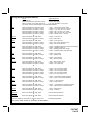
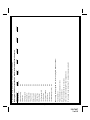
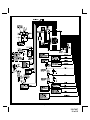
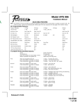
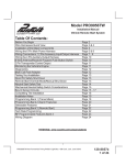
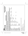
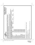
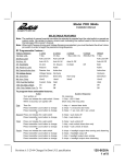
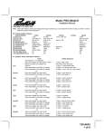
128-7407
1 of 12
1 Chirp
1 Sec.
Accy Lock On
Accy UL Dr.
On Arm
Passive
Passive Arm
Siren/Horn
10mS
Custom Code
On
On
Voltage Sense
NA
NA
2 Chirps
3.5 Sec.
Accy Lock Off
Accy UL All
On Disarm
Active
Active Arm
Siren Only
16mS
Valet
Off
Off
Hardwire
4 Chirps
Dbl L, 1 Sec UL
Off
40mS
3 Chirps
1 Sec L, Dbl. U/L
Accy U/L Off
On Both
Horn Only
30mS
50mS
5 Chirps
Dbl L, Dbl UL
6 Chirps
1 S l/350mS ul
Default
1S/1S
Auto Locks Off
Auto UL Off
w/ Arm& Disarm
Active
Active
Siren/Horn
16mS
Valet
Off
Off
Hardwire
Press and hold valet switch for 5 seconds
Siren chirps 2 times indicating RF feature program mode.
Note: Once you enter the feature programming mode, do not allow more than 15 seconds to pass between steps, or the programming will be terminated.
When using the RF programmer, enter the program mode as follows:
Turn the ignition on
Press and release valet switch 3 times
turn ignition off then on
Feature Selection
1st DoorL/UL
2nd Accy Lock
3rd Accy. UL
4th Headlights
5th Passive Locks
6th Pass/Act Arm
7th Siren/Horn
8th Horn Chirp
9th O/R Method
10th 2 Step U/L
11th Chp Del Tx
12th Volts/HdWire
13th Trigger Ckts
14th L/UL Poll
RF Programmable Features Bank 2 Is Alarm Selectable Features:
RF Programmable Feature Bank 1 Is For Transmitter Programming See Transmitter Programming Guide.
Note : The method of manual override can either be selected to operate from the valet switch or operate as custom code.
Be certain to place a check mark indicating the method used in the box located on the last page of the owner's manual.
NOTE: Keyless Entry Models with no horn output will Flash the Parking Lights instead of chirp where chirp is indicated.
Also, No data will be indicated if a feature is not available for a particular model. The unit will enter the feature but no selection will be available.
SELECTABLE FEATURES
The selectable features can be set manually as explained below, or with the RF feature programmer.
To set features using the RF programmer, follow the instructions packaged with the programmer.
Factory default settings are indicated by bold text.
Installation Manual
Model APS-597
To program these selectable features;
Action
System Response
Turn ignition on
No response
Press and release the valet switch 3 times
1 Chirp - LED 1 flash
Within 3 seconds, turn ignition Off Then On
Long chirp followed by a long chirp
This Action Accesses Feature Bank 2 Alarm Selectable Features
First
Press
Press
Press
Press
Press
Press
Second
Press
Press
Third
Press
Press
Press
Fourth
Press
Press
Press
Press
Fifth
Press
Press
Sixth
Press
Press
Seventh
Press
Press
Press
Eighth
Press
Press
Press
Press
Press
and release the valet switch 1time
transmitter Lock button to change
transmitter Lock button to change
transmitter Lock button to change
transmitter Lock button to change
transmitter Lock button to change
or
and release the valet switch
transmitter Lock button to change
or
and release the valet switch
transmitter Lock button to change
transmitter Lock button to change
or
and release the valet switch
transmitter Lock button to change
transmitter Lock button to change
transmitter Lock button to change
or
and release the valet switch
transmitter Lock button to change
or
and release the valet switch
transmitter Lock button to change
or
and release the valet switch
transmitter Lock button to change
transmitter Lock button to change
or
1
2
3
4
5
6
chirp = 1 second door lock & unlock
chirps = 3.5 second door lock & Unlock
chirps = 1 sec. lock, dbl 1 sec. unlock
chirps = dbl 1 sec lock, 1 sec unlock
chirps = dbl 1 sec lock, dbl 1 sec unlock
chirps = 350mS unlock. 1 sec lock
2 chirps = auto locks off
1 chirp = auto locks on
3 chirps = auto unlock off
1 chirp = auto unlock drivers door only
2 chirps = auto unlock all doors
3
4
1
2
chirps = headlight output when arming and disarming
chirps = headlight output off
chirp = headlight output when arming
chirps = headlight output when disarming
2 chirps = active locks
1 chirp = passive locks
2 chirps = active arming
1 chirp = passive arming
1 chirp = siren and horn output
2 chirps = siren output only
3 chirps = horn output only
and release the valet switch
2 chirps = horn chirp output 16mS
transmitter Lock button to change
3 chirps = horn chirp output 30mS
transmitter Lock button to change
4 chirps = horn chirp output 40mS
transmitter Lock button to change
5 chirps = horn chirp output 50mS
transmitter Lock button to change
1 chirp = horn chirp output 10 mS
or
Ninth
Press and release the valet switch
2 chirps = valet switch override operation
Press transmitter Lock button to change
1 chirp = custom code override operation
or
Tenth
Press and release the valet switch
2 chirps = 2 step unlock off
Press transmitter Lock button to change
1 chirp = 2 step unlock on
or
Eleventh
Press and release the valet switch
2 chirps = chirp delete from transmitter inactive
Press transmitter Lock button to change
1 chirp = chirp delete from transmitter active
or
Twelfth
Press and release the valet switch
1 chirp = voltage sense
Press transmitter lock button to change
2 chirps = hardwire
or
Thirteenth
Press and release the valet switch
Non Functional On This Unit
or
Fourteenth
Press and release the valet switch
Non Functional On This Unit
or
Press and release the valet switch or turn the ignition off to:
Exit Programming Mode
or
Turn ignition switch off then on to advance to feature Bank 3:
Page 2
128-7407
2 of 12
Page 3
128-7407
3 of 12
NA
NA
16th Turbo Select
17th Black/Blue (Aux O/P)
2 Chirps
10 Mins
3 Chirps
To exit program mode, turn ignition off, or press and release valet switch
Siren chirps 2 times indicating RF feature program mode.
Press and hold valet switch for 5 seconds
turn ignition off then on
Press and release valet switch 3 times
Turn the ignition on
When using the RF programmer, enter the program mode as follows:
NA
NA
13th Temp Start
NA
NA
12th Transponder O/P
15th R/S Shock
NA
14th Crank Averaging
NA
NA
7th Ing. 2 Select
11th Gas/Diesel
NA
6th Voltage Level
10th Crank Time
NA
5th Input Check
NA
NA
4th Parking Lights
NA
NA
3rd Run Time
9th Diagnostics
NA
2nd RF Start Chirp
8th Ign. 3 Select
1 Chirp
Pulsed
Feature Selection
1st Defrost Output
4 Chirps
RF Programmable Features Bank 3 Is Remote Start Selectable Features:
To exit program mode, turn ignition off, or press and release valet switch.
5 Chirps
6 Chirps
INSTALLATION OF MAJOR COMPONENTS
Note: This system allows the transmitter to be programmed for single button lock/unlock or separate
button lock/unlock. The receiver is set up as follows:
Channel #1
=
Lock/Unlock/Unlock 2 &Panic
Channel #2
=
If Programmed, Unlock/Unlock 2 & Panic
Channel #3
=
Channel 3 & Alternate Channel 3
Channel #4
=
Channel 4 Output
Channel #5
=
Channel 5 Output (If so Equipped)
During the program routine, if a transmitter button is programmed into receiver channel 2, then the unit will
always have separate lock/unlock from that transmitter.
If during the program sequence receiver channel 1 is programmed, and received channel 2 is skipped over,
as indicated in the transmitted program guide, then the unit will operate as a single button lock/unlock unit
from that transmitter.
It is possible to have one transmitter programmed for single button lock/unlock, and one transmitter programmed for separate button lock/unlock if the customer so desires.
If you inadvertently incorrectly program the transmitter, please read the information on re-prioritizing found
in the transmitter programming guide.
This unit is also capable of single button programming. Simply enter the transmitter program mode and
press the lock, channel one button for each transmitter, then exit the program mode. This action sets the
transmitters for seperate lock/unlock as well programs the trunk release button and the option button.
Control Module:
Select a mounting location inside the passenger compartment ( up behind the dash ), and secure using the
two screws provided. The control module can also be secured in place using cable ties.
Do not mount the control module in the engine compartment, as it is not waterproof. You should also avoid
mounting the unit directly onto factory installed electronic components. These components may cause RF
interference, which can result in poor transmitter range or intermittent operation.
Transceiver, (Antenna Receiver) Assembly:
The Superheterodyne Receiver Antenna Assembly provided with this unit allows routing from below the
dash board for maximum operating range. Choose a location above the belt line (dashboard) of the vehicle
for best reception. Special considerations must be made for windshield glass as some newer vehicles
utilize a metallic shielded window glass that will inhibit or restrict RF reception. In these vehicles, route the
antenna toward a rear window location for best reception. Secure the antenna with double stick tape
provided. After securing the antenna with tape, we advise also securing a section of the antenna cable to
a fixed support. This will prevent the antenna from dropping down in case the double stick tape is exposed
to extreme heat which may loosen it's gummed surface. Route the 4 pin connector toward the control
module using caution not to pinch the cable as this will cause poor or no RF reception to the control
module.
Siren:
Select a mounting location in the engine compartment that is well protected from access below the vehicle.
Avoid areas near high heat components or moving parts within the engine compartment. To prevent water
retention, the flared end of the siren must be pointed downward when mounted.
Mount the siren to the selected location using the screws and bracket provided.
Hood or Trunk Pin Switch:
A pin switch is included for use in protecting the hood or trunk ( or hatchback ) of the vehicle. The switch
must always be mounted to a grounded, metal surface of the vehicle. It is important to select a location
where water cannot flow or collect, and to avoid all drip gutters on hood and trunk fender walls. Choose
locations that are protected by rubber gaskets when the hood or trunk lid is closed.
The pin switch can be mounted using the bracket provided, or direct mounted by drilling a ¼ “ diameter
mounting hole. Keep in mind that when properly mounted, the plunger of the pin switch should depress at
least ¼ “ when the hood or trunk lid is closed.
Dash Mounted LED:
A small LED is included that will serve as a visual indicator of the alarm status. It should be installed in the
dash, located where it can be easily seen from outside the vehicle, yet not be distracting to the driver.
Once a location has been selected, check behind the panel for wire routing access, and to confirm the drill
will not damage any existing components as it passes through the panel.
Page 4
128-7407
4 of 12
Drill a ¼ “ diameter hole, and pass the red and blue wires from the LED through the hole, from the front of
the panel. Firmly press the body of the LED into the hole until fully seated.
Valet Switch:
Select a mounting location for the switch that is easily accessible to the driver of the vehicle. The switch
does not have to be concealed, however, concealing the switch is always recommended, as this provides
an even higher level of security to the vehicle.
The valet switch can be mounted to the lower side of the dash by drilling a ¼ “ diameter hole in the selected
location.
Be sure to check behind the dash for adequate clearance for the body of the switch, and to confirm that the
drill will not damage any existing components as it passes through the dash. Route the two pin connector
toward the control module.
Shock Sensor:
Select a solid mounting surface for the shock sensor on the firewall inside the passenger compartment,
and mount the sensor using the two screws provided. The shock sensor can also be secured to any fixed
brace behind the dash using tie straps.
Whichever mounting method is selected, make certain that the sensitivity adjustment is accessible for use
later in the installation.
WIRING THE SYSTEM
Large 8 Pin Edge Connector:
Red/White (5Amp) & Red Fused (15Amp) Wires : + 12 VDC CONSTANT BATTERY SOURCE
This wire controls the sensitivity of the voltage sensing circuit, which detects the turning on of an interior
light when a door is opened. It will also detect the switching on of parking or headlamps, and in many
cases will trigger the alarm when a thermostatically controlled electronic radiator cooling fan switches on.
When installing this system into vehicles with electronic “ after fans “, it is recommended you disable the
voltage sense circuit.
In voltage sensing applications, the closer to the battery that the red wire is connected, the less sensitive
the voltage sense circuitry will be. Moving this connection point to the fuse panel will increase the sensitivity, and connecting to the courtesy lamp fuse in the vehicle will provide maximum sensitivity of the voltage
sense circuit. Be certain to set selectable feature # 12 to 1 chirp, Voltage Sense On.
When hardwiring the control module to pin switches at all entry points, the voltage sense circuit must be
disabled.
Orange Wire: 300 mA GROUND OUTPUT WHEN ARMED - N. C. STARTER DISABLE
This wire is provided to control the starter cut relay. Connect the orange wire to terminal 86 of the relay.
Connect relay terminal 85 to an ignition wire in the vehicle that is live when the key is in the on and crank
positions and off when the key is in the off position. (This is where the yellow wire from the alarm should
be connected).
Cut the low current starter solenoid wire in the vehicle, and connect one side of the cut wire to relay
terminal 87A. Connect the other side of the cut wire to relay terminal 30.
Note: This is a normally closed starter cut arrangement, and when power is removed from the
security system, the starter disable feature will not operate, allowing the vehicle to start.
Audiovox does not recommend using the Orange wire to interrupt anything but the starting
circuit of the vehicle.
Green w/ White trace Wire: Entry Illumination Ground Output
This wire provides a 30 second ground output (300 mA Max) whenever the remote is used to disarm the
alarm or to unlock the doors and provides a continuous pulsed output whenever the alarm is triggered. This
wire should be connected to an external relay and wired to the vehicles interior entry lighting whenever the
optional Interior Illumination circuit is desired. See Wiring Diagram for details.
Dark Blue Wire: DELAYED 300 mA PULSED OUTPUT / CHANNEL 3
The dark blue wire pulses to ground via an independent RF channel from the keychain transmitter. This is
a transistorized, low current output, and should only be used to drive an external relay coil.
WARNING: Connecting the dark blue wire to the high current switched output of trunk release circuits,
some remote start trigger inputs, will damage the control module.
Connect the dark blue wire to terminal 86 of the AS - 9256 relay (or equivalent 30 A automotive relay), and
wire the remaining relay contacts to perform the selected function of channel 3.
Page 5
128-7407
5 of 12
White w/ Black Trace Wire: POSITIVE OUTPUT TO SIREN
Route this wire through a rubber grommet in the firewall, and to the siren location.
Connect the white / black wire to the positive wire of the siren. Secure the black ground wire of the siren to
chassis ground.
Black Wire: CHASSIS GROUND
Connect this wire to a solid, metal part of the vehicle’s chassis. Be certain that the connection point is
clean unpainted surface to insure proper grounding.
White Wire: + 12 VDC PULSED PARKING LIGHT OUTPUT (15 AMP MAX)
This wire is provided to flash the vehicle’s parking lights. Connect the white wire to the positive side of one
of the vehicle’s parking lights.
Wiring The 11 Pin Mini Edge Connector:
Dark Green w/ Black Trace Wire: LATCHING OUTPUT / CHANNEL 4
The green w/ black trace wire latches to ground via an independent RF channel from the keychain transmitter.
This is a transistorized, low current ( 300 mA ) output, and should only be used to drive an external relay coil.
This wire provides an immediate ground signal, and stays at ground for as long as the button(s) on the
keychain transmitter remains pressed.
WARNING ! Connecting the dark green w/ black trace wire to the high current switched output of
trunk release circuits will damage the control module.
Connect the dark green w/ black trace wire to terminal 86 of the AS 9256 relay (or an equivalent 30 Amp
automotive relay ), and wire the remaining relay contacts to perform the selected function of channel 4.
NOTE: This wire can alternately be used for a rear window defroster output if in the case a remote start is
added, in this case, this wire can be used to activate the rear window defogger either by a single pulsed
ground, or a 10 minute ground output. This selection is available in bank 3 feature 1. The operation is as
follows: When the Blue/Black alternate output wire is activated to start a vehicle, as long as the alarms
ignition input wire is inactive, if the Green/Black channel wire is activated, there will be an output for pulsed
or 10 minutes as selected in the feature bank.
Dark Blue w/Black Trace Wire: Alternate Channel 3 Output (Dbl. Push Required)
This wire is controlled from the transmitter button programmed to the receiver's channel 3. By double
pressing this the transmitter button, this output will become active for 1 second. This is a transistorized,
low current (300 mA) output, designed to provide an output only when the transmitter is intentionally
operated, such as is the case with remote start add on modules. If you require more than 300mA drive from
this output, you must drive an external relay coil, and arrange the relays contacts to preform the specified
function.
NOTE: Pressing the transmitter button, then immediately pressing and holding it will cause this output to
be active as long as the transmitter button is depressed.
Black w/ White Trace Wire: 300 mA Horn Output
The black w/ white trace wire is provided to beep the vehicle’s horn. This is a transistorized low current
output, and should only be connected to the low current ground output from the vehicle’s horn switch.
If the vehicle uses a + 12 VDC horn switch, then connect the black w/ white trace wire to terminal 86 of the
AS 9256 relay ( or an equivalent 30 Amp automotive relay ), and connect relay terminal 85 to a fused + 12
VDC battery source. Connect relay terminal 87 to the vehicle’s horn switch output, and connect relay
terminal 30 to a fused + 12 VDC battery source.
Orange w/ White Trace Wire: 300 mA GROUND OUTPUT WHEN DISARMED - N. O. STARTER DISABLE ( Optional Relay Required ).
This wire is provided to control the starter cut relay. Connect the orange w/white wire to terminal 86 of the
relay. Connect relay terminal 85 to an ignition wire in the vehicle that is live when the key is in the on and
crank positions, and off when the key is in the off position. ( This is where the yellow wire from the alarm
should be connected ).
Cut the low current starter solenoid wire in the vehicle, and connect one side of the cut wire to relay
terminal 87. Connect the other side of the cut wire to relay terminal 30.
Note: This is a normally opened starter cut arrangement, and when power is removed from the
security system, the starter disable feature will remain operational, and the vehicle will
not start. Audiovox does not recommend using the Orange w/ White trace wire to interrupt
anything but the starting circuit of the vehicle.
Page 6
128-7407
6 of 12
Dark Green Wire: ( - ) INSTANT TRIGGER ZONE
This is an instant on ground trigger wire. It must be connected to the previously installed hood and trunk pin
switches.
Brown Wire: - DOOR TRIGGER
If the vehicle’s courtesy light switches have a ( - ) ground output when the door is opened (GM and most
Imports), you must connect this wire to the negative output from one of the door switches.
WARNING: Do not use the brown wire if the vehicle has + 12 volt output type door switches.
(see Purple Wire).
Note for vehicles with interior delay lighting see programming under title "Completing The Installation".
Purple Wire: + DOOR TRIGGER
If the vehicle’s door courtesy light switches have a + 12 volt output when the door is opened (most Fords and
some Imports ), you must connect this wire to the positive output from one of the door switches.
WARNING: Do not use the purple wire if the vehicle has ground output type door switches.
( see Brown Wire ).
Note for vehicles with interior delay lighting see programming under title "Completing The Installation".
Yellow Wire: + 12 VDC IGNITION SOURCE
Connect this wire to a source that is live when the key is in the on and crank positions. Be sure that this
source is off when the key is in the off position.
White w/ Blue Trace Wire: Low Current (-) Ground Headlight Output
The White w/ Blue Trace wire is provided to operate the optional headlamp illumination feature of the system.
This is a low current (300mA) output and must be connected to an external relay to control the high current
switching circuit of the vehicle's headlamps. To use this option, Connect the White /w Blue Trace wire to
terminal # 86 of a P&B VF45F11 relay or equivalent. Connect Terminals #85 and # 30 to a fused + 12 Volts
source with a current capability equal to or in excess of the factory headlamp fuse. Connect terminal # 87 of
the relay to the switched + 12 volt wire feeding the vehicle's headlamp circuit.
NOTE: For ground switched headlamp circuits, Connect the White /w Blue Trace wire to terminal # 86 of a
P&B VF45F11 relay or equivalent. Connect Terminal #85 to a fused + 12 Volts source. Connect
terminal # 30 to a clean chassis ground. Connect terminal # 87 to the ground switched headlamp
control wire in the vehicle.
Light Green Wire: (-) Instant Trigger Zone 1
This is a instant on ground trigger input intended for the connection of optional triggering devices. The ground
trigger output wire of motion detectors, microwave detectors, or glass break detectors, can be connected to
this Light Green trigger input wire.
Light Blue/Green Wire: DELAYED 300 mA PULSED OUTPUT / CHANNEL 5
The light blue/green wire pulses to ground via an independent RF channel from the keychain transmitter. This
is a transistorized, low current output, and should only be used to drive an external relay coil.
WARNING: Connecting the light blue/green to the high current switched output of trunk release circuits,
some remote start trigger inputs, will damage the control module.
Connect the light blue/green to terminal 86 of the AS - 9256 relay (or equivalent 30 A automotive relay), and
wire the remaining relay contacts to perform the selected function of channel 5.
2 Pin White Connector: DASH MOUNTED LED
Route the red and blue wires in the 2 pin white connector from the LED to the control module, and plug it into
the mating white connector on the side of the module.
4 Pin White Connector: SHOCK SENSOR
Route the red, black, blue, and green wires in the 4 pin white connector from the shock sensor to the control
module, and plug one end into the shock sensor, and the other end into the mating white connector on the
side of the module.
Red / Green / Red w/Black Trace 3 Pin White Connector: Door Lock Outputs
The Red and Green wires will provide either a pulsed ground output to the factory door lock control relay, or
a pulsed + 12 volt output to the factory door lock control relay. In either case, the maximum current draw
through these outputs must not exceed 300 mA. The Red w/Black trace wire will provide a pulsed ground
only, and will only provide an output when the unlock button of the transmitter is pressed a second time after
a first unlock command was issued. This is used for second step unlock or all doors unlock in a two step
circuit. In this arrangement, Red, or Green is used to control the drivers door unlock relay, and the Red/Black
will be used to control unlock of all other doors.
Page 7
128-7407
7 of 12
3 Wire Ground Switched Single Step Door Locks
In this application, the red wire provides a ground pulse during arming, or the pulsed ground lock output.
Connect the red wire to the wire that provides a low current ground signal from the factory door lock switch
to the factory door unlock control relay.
The green wire provides a ground pulse during disarming, or the pulsed ground unlock output. Connect
the green wire to the wire that provides a low current ground signal from the factory door unlock switch to the
factory door unlock control relay. Red/Black Not Used.
3 Wire Ground Switched 2 Step Door Locks
In this application, the red wire provides a ground pulse during arming, or the pulsed ground lock output.
Connect the red wire to the wire that provides a low current ground signal from the factory door lock switch
to the factory door lock control relay.
The green wire provides the first ground pulse during disarming, or the drivers door pulsed ground
unlock output. Connect this wire to the drivers door unlock relay that requires a low current ground signal
to unlock only the drivers door. If the vehicle does not have a sperate drivers door relay, one will have to be
added. Locate the drivers door unlock motor wire and cut it at a convenient location to allow wiring of an
optional relay. Connect the door side of the cut wire to terminal 30 of the optional relay added. Connect the
vehicle side of the cut wire to terminal 87a of the optional relay added. Connect the green wire of the 3 pin
harness to terminal 86 of the optional relay added. Connect terminal 85 of the optional relay added to a
fused constant + 12 volt source. Most vehicles door lock/unlock motor legs rest at ground, and switch +12
volts to the door lock/unlock motor legs for operation, if this is the case in the vehicle you are working on,
connect the remaining terminal, 87, to a fused + 12 volt source. In the rare instance that the vehicle door
lock/unlock motor legs rest at + 12 volts and switches ground to the door lock/unlock motors, connect he
remaining terminal, 87, to chassis ground.
The Red/Black wire provides a pulse ground output when the unlock button of the transmitter is pressed a
second time after disarming. Connect the Red/Black wire to the wire that provides a low current ground
signal from the factory door unlock switch to the factory door lock control relay.
3 Wire Positive Switched Door Locks
In this application, the red wire provides a positive pulse during disarming, or the pulsed + 12 volt unlock
output. Connect the red wire to the wire that provides a low current positive signal from the factory door
unlock switch to the factory door unlock control relay.
The green wire provides a positive pulse during arming, or the pulsed + 12 volt lock output. Connect the
green wire to the wire that provides a low current positive signal from the factory door lock switch to the
factory door lock control relay.
3 Wire Positive Switched 2 Step Door Locks
The green wire provides a positive pulse during arming, or the pulsed + 12 volt lock output. Connect the
green wire to the wire that provides a low current positive signal from the factory door lock switch to the
factory door lock control relay.
The red wire provides a positive pulse during disarming, or the drivers door pulsed positive unlock
output. Connect this wire to the drivers door unlock relay that requires a low current positive signal to
unlock only the drivers door. If the vehicle does not have a separate drivers door relay, one will have to be
added. Locate the drivers door unlock motor wire and cut it at a convenient location to allow wiring of an
optional relay. Connect the door side of the cut wire to terminal 30 of the optional relay added. Connect the
vehicle side of the cut wire to terminal 87a of the optional relay added. Connect the red wire of the 3 pin
harness to terminal 86 of the optional relay added. Connect terminal 85 of the optional relay added to
chassis ground. Most vehicles door lock/unlock motor legs rest at ground, and switch +12 volts to the door
lock/unlock motor legs for operation, if this is the case in the vehicle you are working on, connect the
remaining terminal, 87, to a fused + 12 volt source. In the rare instance that the vehicle door lock/unlock
motor legs rest at + 12 volts and switches ground to the door lock/unlock motors, connect he remaining
terminal, 87, to chassis ground.
The Red/Black wire provides a pulse ground output when the unlock button of the transmitter is pressed a
second time after disarming. Because the vehicle you are working on requires a positive pulse from the
factory door lock switch to the factory door lock control relay, you will have to add a relay to invert the output
polarity of this wire. Connect the Red/Black wire to terminal 86 of the optional added relay. Connect
Page 8
128-7407
8 of 12
terminal 85 & 87 to a fuse + 12 volt source. Connect terminal 30 to the low current door unlock wire from the
factory door switch to the door unlock control relay.
Resistive Circuits, As Well As 4 Wire Polarity Reversal and 5 Wire Alternating 12 Volt
Door Lock Control Circuits
These applications require the use of additional components which may include relays, fixed resistors, or for
convenience, the AS 9159 Door Lock Interface. Refer to the AUDIOVOX Door Lock Wiring Supplement and
or the Audiovox fax back service for information on your particular vehicle for properly connecting to these
types of circuits.
4 Wire Antenna Cable:
If you've not done so already, be certain to connect the Red/Green/Black/Blue 4 wire transceiver cable
assembly to both the antenna assembly, and the mating connector of the control module or your transmitters will not operate.
4 Pin Upgrade Telematic Module:
Red = + 5 Volts / Black = Ground / White = Data TX / Yellow = Data RX
Connect the 4 pin harness found in the Telematic one way module kit to the mating port on the PTUGM.
NOTE: If using the TWO WAY Telematic module, only Ground, TX, and RX are used on this port, the + 12 volt supply
for the two way module must be sourced separately or the unit will not operate.
4 Pin Data Bus Upgrade Module Connector:
The brown 4 pin data bus upgrade module connector located on the side of the module is designed to allow direct
plug in of specific Audiovox upgrade data bus modules which when used will facilitate installation in certain
vehicles.
COMPLETING THE INSTALLATION
NOTE: This unit has the ability to learn the dome light delay time, up to 60 seconds. If the vehicle has
delay interior lights, and you wish to avoid three chirp, defect zone, indication normally associated with
this type of interior light, we suggest you learn the interior light delay.
To learn the light delay, start with all doors closed:
(1) Use the transmitter to Lock / Unlock / Lock / Unlock / Lock / Unlock / Lock, the system.
The LED turns on solid to confirm the system entered the learn mode.
(2) Immediately open and close the door of the vehicle to initiate the dome delay.
The unit will monitor the door trigger input Positive, (Purple), and Negative, (Brown) when active.
When the dome light turns off, the unit will add 2 seconds then exit the learn mode.
(3) The LED will begin flashing the Armed indication indicating the unit has exited the learn mode and is
armed.
Adjusting the Shock Sensor: If used, the sensitivity of the pre - detect circuit is automatically set 30% less
sensitive than the full trigger circuit.
Using a small screwdriver, gently turn the adjustment screw fully counterclockwise. (DO NOT over turn this
screw. Maximum rotation for this adjustment is 270°). Close the hood and trunk lids, and arm the alarm.
Wait 6 seconds for the accessories trigger zone to stabilize, then firmly strike the rear bumper with the side
of a closed fist considering the amount of force required to break a window.
CAUTION: Never perform this test on the vehicle’s glass, as you may break the window.
Turn the adjustment screw clockwise (increasing sensitivity) about ¼ turn and re-test. Repeat this
procedure until the alarm sounds. Ultimately, one firm strike to the rear bumper will cause the alarm to emit
pre-detect warning tones.
WARNING ! Setting the sensitivity too high can cause false alarms due to noise vibrations from passing trucks
and heavy equipment. To decrease sensitivity, turn the adjustment screw counter clockwise.
Wire Dressing: Always wrap the alarm wires in convoluted tubing, or with a spiral wrap of electrical tape.
Secure these looms along the routing using cable ties. This will ensure that the alarm wires are not
damaged by falling onto hot or sharp moving surfaces in the vehicle.
Operation: Take a few moments to check off the appropriate option boxes in the owner’s manual, and to
fully explain the operation of the system to your customer.
Place the Valet Switch Tag and or the Remote Start Control Switch Tag on their respective switches and
point these out to the customer.
Page 9
128-7407
9 of 12
Page 10
128-7407
10 of 12
THIS PAGE LEFT BLANK INTENTIONALLY
Page 11
128-7407
11 of 12
© 2005 Audiovox Electronic Corporation, 150 Marcus Blvd., Hauppauge, N.Y. 11788
128-7407
Page 12
128-7407
12 of 12