1
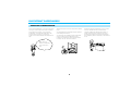
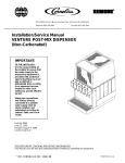
VIDEO CASSETTE PLAYER MODEL AVP-8280 OPERATING INSTRUCTIONS CAUTIONS AND WARNINGS To obtain the best results and to avoid malfunctions, PLEASE READ CAREFULLY THE DESCRIPTIONS AND OPERATING PROCEDURES CONTAINED IN THIS OWNER’S MANUAL PRIOR TO OPERATING THE VIDEO CASSETTE PLAYER. CAUTION RISK OF ELECTRIC SHOCKS DO NOT OPEN CAUTION: TO REDUCE THE RISK OF ELECTRIC SHOCK, DO NOT REMOVE THE COVER. NO USER-SERVICEABLE PARTS INSIDE. REFER SERVICING TO QUALIFIED SERVICE PERSONNEL. This user manual employs the following symbols to indicate different types of warning messages. Indicates a warning or notice regarding product operation. Indicates the presence of important operating and maintenance (servicing) instructions. Indicates the presence of un-insulated dangerous voltage within the unit enclosure. WARNING: TO PREVENT FIRE OR ELECTRIC SHOCK, DO NOT EXPOSE THIS APPLIANCE TO RAIN OR MOISTURE. AVERTISSEMENT: POUR PRÉVENIR LES RISQUES D’INCENDIE ET D’ÉLECTROCUTION, NE PAS EXPOSER CET APPAREIL À LA PLUIE NI À L’HUMIDITÉ. Note to CATV system installer: When installing this equipment in the home adhere to Article 820-40 of the NEC that provides guidelines for proper grounding and, in particular, specifies that the cable ground shall be connected to the grounding system of the building, as close to the point of cable entry as practical. NOTE: This equipment has been tested and found to comply with the limit for a Class B digital device, pursuant to Part 15 of the FCC Rules. These limits are designed to provide reasonable protection against harmful interference in a residential installation. This equipment generates, uses and can radiate radio frequency energy and if not installed and used in accordance with the instructions may cause harmful interference to radio communications. However, there is no guarantee that interference will not occur in a particular installation. If this equipment does cause harmful interference to radio or television reception, it can be determined by turning the equipment off and on. The user is encouraged to try to correct the interference by one or more of the following measures: - Reorient or relocate the receiving antenna. - Increase the separation between the equipment and receiver. - Connect the equipment into an outlet on a circuit different from that to which the receiver is connected. - Consult the dealer or an experienced radio/TV technician for help. RECOMMENDED GUIDELINES FOR THE USE OF A VIDEO MONITOR/TV IN A MOTOR VEHICLE • A VIDEO MONITOR/TV is designed for rear passenger viewing only. This product may only be installed in the rear seat compartment of the vehicle, out of the driver’s view. • Installation in any other area of the vehicle within the driver’s view, is illegal in most states, provinces and countries and may lead to driver distraction resulting in an accident, injury and/or death. If you are unsure of regulations, please consult your local laws to determine how this applies to you. • Users should be aware of the possible noise distraction caused by the use of the product and should carefully monitor the volume so as not to interfere with the driver’s attention to surrounding traffic conditions. 1 TABLE OF CONTENTS NOTE: This Video Cassette Player (VCP) is compatible with any Video Cassette bearing the VHS mark. The Video Cassette Player is designed to expand your opportunities for home or mobile viewing and is not intended for any usage which might violate the copyright laws. Save the original shipping carton and packing materials; they will come in handy if you ever have to ship your VCP. For maximum protection, repack the set as it was originally packed at the factory. SAFETY INSTRUCTIONS .............................................................................................................................................................................. 3 IMPORTANT SAFEGUARDS ........................................................................................................................................................................ 4 VIDEO HEAD CLEANING .............................................................................................................................................................................. 6 FEATURES ...................................................................................................................................................................................................... 7 CONTROLS AND INDICATORS .................................................................................................................................................................... 8 REMOTE CONTROL .................................................................................................................................................................................... 12 REMOTE CONTROL BATTERY REPLACEMENT ........................................................................................................................................ 13 GETTING STARTED ..................................................................................................................................................................................... 14 BASIC OPERATION ..................................................................................................................................................................................... 16 SPECIAL OPERATION ................................................................................................................................................................................. 18 BEFORE CALLING AUDIOVOX TECHNICAL SUPPORT (1-800-645-4994) ............................................................................................... 22 SPECIFICATIONS ......................................................................................................................................................................................... 25 2 SAFETY INSTRUCTIONS 1 2 3 4 5 6 7 8 9 10 Read Instructions-All the safety and operating instructions should be read before the Video Cassette Player is operated. Retain Instructions- The safety and operating instructions should be retained for future reference. Heed Cautions and Warnings-All cautions and warnings regarding the Video Cassette Player should be adhered to. Follow Instructions-All operating instructions should be followed. Cleaning-Unplug or turn off vehicle power to the Video Cassette Player before cleaning. Do not use liquid cleaners or aerosol cleaners. Use only a damp cloth for cleaning. Attachments-Do not use attachments not recommended by the Video Cassette Player manufacturer as they may cause hazards. Water and Moisture-Do not use this video product near water, for example, near a bath tub, kitchen sink, near a swimming pool or other wet locations. Accessories-Do not place the Video Cassette Player on an unstable cart, stand, tripod, bracket, or table. The Video Cassette Player may fall, causing serious injury to a child or adult, and serious damage to the Video Cassette Player. Use only with a cart, stand, tripod, bracket, or table recommended by the manufacturer or sold with the Video Cassette Player. When used in vehicles, the Video Cassette Player must be securely fastened. Ventilation-Slots and openings in the cabinet are provided for ventilation to ensure reliable operation of the Video Cassette Player and to protect it from overheating. These openings must not be blocked or covered. The openings should never be blocked by placing the Video Cassette Player on a bed, sofa, rug, or other similar surface. The Video Cassette Player should never be placed near or over a radiator or heat register. This video product should not be placed in a built-in installation such as a book case or rack unless proper ventilation is provided. Power Sources-The Video Cassette Player should be operated only from the type of power source indicated on the marking label. If you are not sure of the type of power supply to your home, consult your appliance dealer or local power company. For video products intended to operate from battery power or other sources, refer to the operating instructions. For your protection, record the model and serial numbers of your video cassette player here. In the event your player requires servicing or is stolen, you may need this information. You may also wish to clip or staple your sales receipt to this page. 3 Model Number: Serial Number: Date Purchased: Store’s Name and Address: IMPORTANT SAFEGUARDS MOISTURE CONDENSATION In the normal temperature, if you pour a cold liquid into a glass, water vapor in the air will condense on the surface of the glass. This is moisture condensation. The moisture condensation may occur inside of VCPs which, if used in this condition, will cause damage to the head and the tape. When moving the VCP from a cold place to heated place. Or the temperature of surroundings goes up due to room heating switched on. Or moving the VCP suddenly from air conditioned room to a place of high temperature and/or humidity in summer may cause the dew indicator to light up. Do not use in this condition. When does the moisture condensation occur inside of the VCP? 4 When the moisture condensation occurs inside of the VCP, NEVER insert the cassette into the cassette compartment. Remove the cassette, if loaded, by pressing the STOP/EJECT key. Only operate the VCP after the moisture condensation has completely dried out. Normally, it takes about 2 hours. SERVICE –If the set has been subjected to excessive shock by being dropped, or the cabinet has been damaged. –When the set exhibits a distinct change in performance, this indicates a need for service. Servicing–Do not attempt to service the set yourself as opening or removing covers may expose you to dangerous voltage or other hazards. Refer all servicing to qualified service personnel. –If the set does not operate normally when following the operating instructions, adjust only those controls that are specified in the operating instructions. Improper adjustment of other controls may result in damage and will often require extensive work by a qualified technician to restore the set to normal operation. Replacement of parts–When replacement of parts is required, be sure the service technician has used replacement parts specified by the manufacturer that have the same characteristics as the original parts. Unauthorized substitutions may result in fire, electric shock, or other hazards. Safety Check–Upon completion of any service or repairs to the set, ask the service technician to perform routine safety checks (as specified by the manufacturer) to determine that the set is in safe operating condition. SERVICE DEPT ALL SETS RECEIVE OUR OK SAFETY CHECK. 5 VIDEO HEAD CLEANING VIDEO HEAD CLOGGING The video heads enable the VCP to read video information pictures from the tape during playback. In the unlikely event that the heads become clogged with dirt video playback will be impossible. This can easily be determined if, during playback of a known good tape, there is good sound, but the picture is extremely snowy. If this is the case, have the video cassette player checked by qualified service personnel. VIDEO HEAD CLEANING NOTES During normal operation of the VCP, the video and audio heads can accumulate dirt over a period of time, especially when using an old or poor quality tape. When the heads are dirty, the picture can get snowy and the tracking control will have little or no effect. If this condition occurs, head cleaning cartridges may take care of the problem and restore normal picture. We recommend that head cleaning cartridges be used sparingly since they are very abrasive and can damage the video heads during prolonged use. If the problem is not resolved with the head cleaning cartridge then the unit needs to be checked by a qualified service personnel. NOTE: Video heads may eventually wear out and should be replaced when they fail to reproduce clear pictures. To help prevent video head clogging, use only good quality VHS tapes. Discard worn out tapes. Do not leave tapes on the floor of the vehicle. Store tapes not being used in their cases. Do not leave video tapes inside a hot vehicle. 6 FEATURES CONGRATULATIONS on your purchase of the Audiovox Model AVP-8280 Video Cassette Player. This unit is designed to satisfy all your VHS tape playback needs and with proper use and care, will offer many years of viewing enjoyment. The features of the Model AVP-8280 Video Cassette Player include: • DIGITAL AUTO TRACKING This VCP plays clear pictures without special operations. In the Auto Tracking Mode, the PLAY indicator blinks. • SELF PICTURE ADJUSTMENT Since HEAD DRUM rotation continuously compensates for voltage change or tape condition, the picture is always stable. • AUTO START FUNCTION This VCP will automatically power on and go into PLAY mode when a cassette is inserted. • 4-HEAD Hi-Fi PLAYBACK • AUTO REPEAT PLAYBACK In the AUTO REPEAT mode, the VCP will , at the end of the tape ,rewind and enter the playback mode. • TWO TYPES OF INFRARED (IR) INPUT FOR REMOTE CONTROL Two-wire interface with various Audiovox IR products such as VOH-681/682 (P/N 136-B1864) and IR receiver accessory (5M). (P/N 136-B2129) • DC Operation with specialized tape mechanism • Diamond Like Coated (DLC) Video Head A special coating on the tape drum which prevents oxide and moisture build-up. • IIluminated function buttons • DEW SENSOR Prevents a tape from being played when moisture is detected in the unit. • ON SCREEN DISPLAY 7 CONTROLS AND INDICATORS FRONT PANEL toggled by pressing this key. When the POWER is switched on, the power lamp will light up in red and the other function buttons light green. $ CST-IN Indicator Lights green when the cassette is inserted. ! Cassette Compartment Accepts the VHS tape for playback. @ Remote Control Receiver # Power Button When pressed this button alternately turns the VCP on and off. When power is applied to the unit, the power indicator lights red. The Power ON and Power OFF mode will be 8 CONTROLS AND INDICATORS (CONTINUED) will fast forward at high speed. ) Tracking +/In the playback mode, this button allows the manual reduction of streaks which may appear on the picture during regular or slow motion playback. Reduces picture “jitter” during play-pause mode. Use these buttons to select AV1 and AV2 when the VCP is in any mode other than play. When VCP is in play mode, AV1 and AV2 are overridden by VCP playback and these buttons adjust tracking only. 1 Auto Repeat Button The VCP cycles through the following mode and the indicator lights orange. The tape will play to the end, rewind to the beginning and play again. When this function is enabled, all control functions are disabled. 2 AUDIO/VIDEO IN Jacks Connect these jacks to the audio/video out jacks terminal of your Game machine or Camcorder using the RCA cord provided. % DEW (Red)/ Hi-Fi (Green) Indicator When power is on, this indicator flashes red to indicate excessive moisture buildup inside the VCP. The unit will not operate until it dries out sufficiently (the tape can be ejected from the unit). When DEW mode has been activated, leave the unit on to allow it to dry out completely. When detected Hi-Fi audio mode in the playback mode, this indicator flashes green. ^ Stop/Eject Button When pressed once, the tape is stopped. When pressed again the tape is ejected. & Rewind/Review Button If this button is pressed in the PLAYBACK mode, the VCP enters the reverse picture search mode. If pressed in STOP mode, the tape wiII rewind at high speed and the REW indicator will light orange. * PLAY Button Press this key to play back a recorded tape. In the playback mode, the playback indicator lights orange, and in Auto Tracking mode, this indicator will blink. ( Fast Forward/Cue Button When this button is pressed during playback, the FF indicator lights orange and the VCP enters the forward picture search mode. When pressed during stop, the tape 9 CONTROLS AND INDICATORS (CONTINUED) REAR PANEL ! Infrared (IR) INPUT Connector @ DC 12V Jack When using a DC power source, connect this jack to 12V DC. * Connector description This connector provides a two-wire interface with various Audiovox IR products such as VOH-681/682.(P/N 136B1864) * Connector description 10 CONTROLS AND INDICATORS (CONTINUED) # AUDIO/VIDEO OUT Connectors These connectors provide an interface to the AUDIO/VIDEO IN connectors of your video monitor, using an RCA cord. $ AUDIO/VIDEO IN Connector These connectors provide an interface to the AUDIO/VIDEO OUT connectors of your Game machine or Camcorder using an RCA cord. % Infrared (IR) INPUT Connector (3.5mm jack) This connector provides a three-wire interface with receiver accessory. (Remote Eye). (P/N 136-B2129) CAUTION: This VCP is for 12Vdc use only; DO NOT use in 24Vdc vehicles. If you use this unit in a 24Vdc vehicle, all the indicator lamps will blink indicating a major malfunction. Disconnect the plug from the power source immediately. 11 CONTROLS AND INDICATORS (CONTINUED) REMOTE CONTROL Turns the VCP on and off. Use this button to eject the cassette tape from the VCP. In STOP mode use this button to select between Video 1 and Video 2 inputs. In PLAY mode use this button to adjust the tracking. In STOP mode use this button to rewind the tape. In PLAY mode use this button to view the tape in reverse. In STOP mode use this button to start tape play. In PLAY mode use this button to enable the Auto Tracking function. In STOP mode use this button to fast forward. In PLAY mode use this button to view the tape in forward. Use this button to pause the tape while playing. Use this button to stop the tape. Use this button to view the tape in slow motion. Use this button to select between Video 1 and Video 2 inputs. Use this button to display the tape counter on the video screen. Use this button to enable the Auto Repeat function. The tape will play to the end, rewind to the beginning and play again. When this function is enabled all controls functions are disabled. Use this button to select audio listening preferences. The VCP can output an audio signal in the following manner. •Hi-Fi (Stereo) •Hi-Fi L •Hi-Fi R •Mono 12 CONTROLS AND INDICATORS (CONTINUED) REMOTE CONTROL BATTERY REPLACEMENT Before attempting to operate your Remote Control, install the batteries as described below. 1 Turn the Remote Control face down. Using a fingernail, lift the battery cover up and off. 2 Install the 3V Lithium Cell battery as shown. Make sure that proper polarity (+) is observed. NOTE : Insert the battery beneath the battery case holding pins. 3 Close the battery cover. REMOTE CONTROL (backside) 3V LIT UM CELL HI CR2025 + battery COVER 13 GETTING STARTED VCP TO VEHICLE CONNECTION • Connect the unit to a 12Vdc source only. • The unit should be connected to the vehicle only after verifying the polarity of the cigarette lighter socket. (12Vdc with negative ground) 14 GETTING STARTED (CONTINUED) 12 VOLT POWER NOTES • This VCP operates on 12Vdc only. If you apply more than 18Vdc, the VCP will automatically turn off. • If the polarity is reversed, the unit will not operate. • Use of this VCP is not recommended in excessive heat. If the inside temperature of the vehicle is over 100F, do not use the VCP. Allow the VCP to cool before use. 15 BASIC OPERATION CASSETTE LOADING/UNLOADING LOADING UNLOADING Œ Push the cassette into the cassette compartment gently. (Arrow mark at the top) Œ Press the VCP STOP/EJECT button twice (in the PLAYBACK mode). The first press stops the tape, while the second press ejects the tape. The CST-IN indicator will turn off. • An inverted cassette cannot be inserted. ´ When a cassette is inserted the CST-IN indicator lamp will turn on. ´ Pull the cassette out gently. • Upon inserting the cassette, the VCP power will turn on and cassette will begin to play as long as DC power is applied to the VCP. • When you press the STOP/EJECT button, the cassette will be ejected as long as power is applied to the unit, even if the power switch is “off”. 16 BASIC OPERATION (CONTINUED) Œ LOADING The power will turn on automatically when a cassette is inserted even if the power switch was off. ´ PLAYBACK ˇ STOP When the PLAY button is pressed the picture will appear within approximately 8 seconds. The tape will rewind automatically to the beginning after the end of the tape is reached and will eject. Press the STOP/EJECT button once to stop playback of the tape. ¨ FAST FORWARD ˆ REWIND Ø EJECT Press the FF button in the STOP mode and the tape will advance at high speed without a picture or sound. Press the REW button in the STOP mode and the tape will rewind at high speed without a picture or sound. Press the STOP/EJECT button once more (in the STOP mode), and the tape will eject. 17 SPECIAL OPERATION The VCP will enter the playback mode as soon as the PLAY key is pressed. During special operations, noise bars and loss of color may affect the picture. This is not due to a VCP malfunction. Œ TO VISUALLY SEARCH FORWARD ´ TO VISUALLY SEARCH REVERSE Press the FF button once in the PLAYBACK mode and the tape will advance rapidly with the pictures. Press the REW button once in the PLAYBACK mode and the tape will rewind rapidly with the pictures. ˇ TO OPERATE RE-AUTO TRACKING Press the PLAY button during playback and the VCP will enter the Re-Auto Tracking mode. 18 SPECIAL OPERATION (CONTINUED) ¨ AUTO REPEAT PLAYBACK • Press the PLAY button for 2 seconds or A.REPEAT button in the playback mode. The AUTO REPEAT light will illuminate. The VCP cycles through the following modes and the AUTO REPEAT lamp lights red. The tape will play to the end, rewind to the beginning and play again. “PLAYBACK THE END OF THE TAPE REWINDING PLAYBACK”. • Other controls have no effect during the Auto Repeat mode. • To exit the Auto Repeat mode, press the PLAY button for 2 seconds or A.REPEAT button again. The AUTO REPEAT indicator will turn off and stop the tape. PLAY Button A. REPEAT Button 19 SPECIAL OPERATION (CONTINUED) ˆ VCP TO GAME MACHINE OR CAMCORDER CONNECTION • If you connect a Video Game machine or a Camcorder to the VCP, you can view the Video Game machine or Camcorder video on a video monitor connected to the output of the VCP. • During the Playback mode of the VCP or the Cue/Review mode, the VCP has priority over the front and rear jacks. 20 SPECIAL OPERATION (CONTINUED) Ø AUTO TRACKING ADJUSTMENT • Since this VCP features the Auto Tracking Adjustment function, it will play clear pictures. • Auto Tracking Adjustment operates automatically when the cassette is inserted. • The orange Playback indicator will blink during the auto tracking operation. When tracking is completed, the Playback indicator lights steadily. • If noise bars appear in the picture during Playback, press the PLAY key to initiate the Auto-Tracking function. PLAY Button NOTE : This VCP has an Auto Start Feature whereby the unit will automatically power on and go into PLAY mode when a cassette is inserted, provided the unit is connected to a power source. 21 BEFORE CALLING AUDIOVOX TECHNICAL SUPPORT (1-800-645-4994) Before calling, check the following points for a possible cause of the trouble. A minor adjustment on your part may eliminate the problem. SYMPTOMS CAUSE POSSIBLE SOLUTIONS There is no power to the VCP. • The power cord is not connected. • The polarity of power cord is not correct. • Check the power cord. • Change the polarity of power cord. Noise bars on screen. • Tracking is not adjusted. • Adjust for a clear picture by pressing the PLAY button. Operation key does not work. • If the cassette or the VCP is not in normal condition, every LED indicator lights and the VCP is inoperative. • Turn the power off and on by pressing the POWER button. • Unplug and re-plug the power cord. Cassette is ejected upon inserting. • Safety device works to protect the cassette when it is inserted incorrectly. • Pull the cassette out (unloading) and insert it firmly into the cassette compartment. Audio output does not change to Hi-Fi mode. • The cassette was recorded on a in mono VCR. • The first autotracking attempt is still executing now. • The cassette can not be played back in Hi-Fi mode. • Wait for a second. 22 SYMPTOMS CAUSE POSSIBLE SOLUTIONS No back-lighting at POWER button. • No 12V DC. • Check circuit fuse at source of power (see vehicle/converter manual). • Check in-line fuse of power cord (in lighter plug). • Power cord unplugged from 12V outlet or at rear of unit. Power indicated with back-lighting but unit will not operate. • Dew feature activated (See owner’s manual for dew mode explanation). • Retain power to player and allow unit time to get rid of moisture. (After 30 minutes if dew indicator is still on, completely switch off unit power and re-apply after 1 minute. This can reset dew indicator if moisture is eliminated.) • No tape in unit. • Insert the tape. • Low voltage. • Start the vehicle, if not running. More indicators flashing; unit will not operate. • Unit in emergency mode. • Contact dealer for service to player. PLAY mode indicated no audio or video on to TV. • VCP connected to TV A/V Input jack. • TV in TV mode • Switch TV to video mode with remote control or switch behind control door of TV. Refer to your TV Owner’s Manual for further information. 23 SYMPTOMS Play mode indicated but no audio or video to TV. (continued) CAUSE POSSIBLE SOLUTIONS • VCP connected by (75 OHM coax) antenna coax to TV. TV set in “monitor mode”. • Switch to TV mode. • VCP connected to A/V output jacks. (AVT-1475 or 1498) • Change connections from A/V output to A/V input. • Output of VCP A/V RCA cables or coax not connected to TV input. • Check connector between VCP and TV. • Switchable input device used between TV and VCP (game prep). Poor video/snowy picture or lines on screen. • Poor connection between VCP output and TV input. • Check connection(a). • Reversed A/V inputs to TV. • Check connection(b). • Shorted coax cable between VCP and TV. • Check cable/by pass or continuity test. • Dirty Heads. • Clean head using tape cartridge cleaner. We recommend using cartridge with cloth or paper tape and cleaning drops included. These are readily available at retail stores. 24 SPECIFICATIONS MODEL AVP-8280 POWER SUPPLY 12Vdc POWER CONSUMPTION 13Watts DIMENSION 248 X 91 X 260 (W X H X D) mm WEIGHT APPROX. 3 kg VIDEO SIGNAL SYSTEM NTSC Color VIDEO SIGNAL OUTPUT (RF)VHS Composite video 1Vpp, 75 ohms unbalanced AVX. TAPE TYPE VHS Type TAPE SPEED SP:33.35mm/sec, LP:22.23mm/sec, SLP:11.12mm/sec FF/REW TIME (T-120) Approx. 3 min VIDEO SIGNAL OUTPUT (LINE) 1Vpp 75 ohm unbalanced, NEGATIVE SYNC AUDIO SIGNAL OUTPUT (LINE) -7.8dBm 10Kohm MAX OPERATION CONDITION HUMIDITY 85% RH max, Temperature:5°C~35°C (41°F~95°F ) OPERATION POWER VOLTAGE 12~14Vdc Design and specifications are subjected to change without notice. 25 36 MONTH LIMITED WARRANTY Applies to Audiovox Mobile Video Products AUDIOVOX ELECTRONICS CORP. (the Company) warrants to the original retail purchaser of this product that should this product or any part thereof, under normal use and conditions, be proven defective in material or workmanship within 36 months from the date of original purchase, such defect(s) will be repaired or replaced with reconditioned product (at the Company's option) without charge for parts and repair labor. To obtain repair or replacement within the terms of this Warranty, the product is to be delivered with proof of warranty coverage (e.g. dated bill of sale), specification of defect(s), transportation prepaid, to the Company at the address shown below. This Warranty does not extend to the elimination of externally generated static or noise, to correction of antenna problems, to costs incurred for installation, removal or reinstallation of the product, or to damage to tapes, discs, speakers, accessories, or vehicle electrical systems. This Warranty does not apply to any product or part thereof which, in the opinion of the Company, has suffered or been damaged through alteration, improper installation, mishandling, misuse, neglect, accident, or by removal or defacement of the factory serial number/bar code label(s). THE EXTENT OF THE COMPANY'S LIABILITY UNDER THIS WARRANTY IS LIMITED TO THE REPAIR OR REPLACEMENT PROVIDED ABOVE AND, IN NO EVENT, SHALL THE COMPANY'S LIABILITY EXCEED THE PURCHASE PRICE PAID BY PURCHASER FOR THE PRODUCT. This Warranty is in lieu of all other express warranties or liabilities. ANY IMPLIED WARRANTIES, INCLUDING ANY IMPLIED WARRANTY OF MERCHANTABILITY, SHALL BE LIMITED TO THE DURATION OF THIS WRITTEN WARRANTY. ANY ACTION FOR BREACH OF ANY WARRANTY HEREUNDER INCLUDING ANY IMPLIED WARRANTY OF MERCHANTABILITY MUST BE BROUGHT WITHIN A PERIOD OF 48 MONTHS FROM DATE OF ORIGINAL PURCHASE. IN NO CASE SHALL THE COMPANY BE LIABLE FOR ANY CONSEQUENTIAL OR INCIDENTAL DAMAGES FOR BREACH OF THIS OR ANY OTHER WARRANTY, EXPRESS OR IMPLIED, WHATSOEVER. No person or representative is authorized to assume for the Company any liability other than expressed herein in connection with the sale of this product. Some states do not allow limitations on how long an implied warranty lasts or the exclusion or limitation of incidental or consequential damage so the above limitations or exclusions may not apply to you. This Warranty gives you specific legal rights and you may also have other rights which vary from state to state. U.S.A. : AUDIOVOX ELECTRONICS CORPORATION, 150 MARCUS BLVD., HAUPPAUGE, NEW YORK 11788 •1-800-645-4994 CANADA : CALL 1-800-645-4994 FOR LOCATION OF WARRANTY STATION SERVING YOUR AREA 128-5148D 26 Thank you for purchasing the Audiovox Model AVP-8280 Video Cassette Player. This instrument is listed by Underwriter’s Laboratories, Inc. It is designed and manufactured to meet rigid U.L. safety standards against X-radiation, fire, casualty and electrical hazards. Audiovox Electronics Corporation 150 Marcus Blvd., Hauppauge, NY 11788 (128-6419)