1
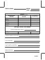
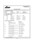
Model PRO 9243
Installation Manual
PRE-INSTALLATION NOTES:
AUTO LOCK / UNLOCK: DIP SWITCH # 1
The system is shipped with this feature activated. Any time the ignition key is turned to the off position, the doors will
automatically unlock. Any time the ignition key is turned to the on position, the doors will automatically lock.
To disable the auto lock / unlock feature, move dip switch number 1 to the "off" position.
PASSIVE / ACTIVE DOOR LOCK SELECTION: DIP SWITCH # 2
This feature will only affect the operation of the system if the passive arming feature is selected.
When active door lock is selected, the doors will only lock when the transmitter button is pressed. When the alarm is
allowed to arm passively, at the end of the 30 second arming cycle, the doors will not automatically lock. The system
is shipped in the active door lock mode, therefore, no modifications are required for this feature.
When passive door lock is selected, when the alarm is allowed to arm passively, at the end of the 30 second arming cycle,
the doors will automatically lock. To program this feature, move dip switch number 2 to the on position.
PASSIVE / ACTIVE ARMING SELECTION: DIP SWITCH # 3
This alarm can be programmed to operate as either a “PASSIVE” or “ACTIVE” arming security system.
As a “Passive” alarm, the system will automatically arm itself approximately 30 seconds after the ignition key is turned
off, one door is opened, then all vehicle doors are closed, (arming is suspended until the last door is closed). This feature
protects the vehicle in the event you forget to arm the system using the keychain transmitter. When the optional door lock
interface is installed, the doors will operate according to the position of dip switch number 2.
This system is shipped in the passive mode, therefore no modifications are required to make the system operate as a
“Passive” alarm.
As an “Active” alarm, the system can only be armed using the keychain transmitter. There will be no backup
automatic arming. To make the system operate as an “Active” alarm, move dip switch number 3 to the off position.
VOLTAGE SENSE / HARDWIRE SELECTION: DIP SWITCH # 4
This alarm can be wired to operate as a Voltage Sensing or a Hardwire system.
As a voltage sensing system, the alarm will trigger any time an entry point that illuminates a courtesy light is opened.
The system is shipped in the voltage sensing mode, therefore, no modifications are required to make this system a voltage
sensing alarm.
As a hardwire system, the alarm will trigger any time a door, hood, trunk, etc. is opened, by wiring directly to the switches.
This means that if the courtesy light is burned out, or the courtesy light fuse is blown, the alarm will continue to protect
all points of entry. To make this system operate as a hardwire alarm, move dip switch number 4 to the off position.
NOTE: When “Passive Arming” and “Voltage Sensing” are selected, you must hardwire the driver’s door pin switch,
or passive arming will never be initiated.
REMOTE ENTRY ILLUMINATION: (OPTIONAL RELAY REQUIRED)
This system provides a ground output (300 mA Max) to drive an external relay that can be used to illuminate the dome
light for 30 seconds whenever the system is disarmed.
This circuit will also flash the interior dome light when the alarm is triggered.
Since a relay is required, (not included), this feature can be used with both positive and negative switched dome light
circuits.
128-4301
DOOR LOCK / UNLOCK OUTPUTS:
This system provides both (+) & (-) pulsed door lock outputs, for direct connection to most OEM factory installed door
lock control relays. These outputs have a maximum current capability of 300 mA , therefore, external relays must be used
on switching circuits requiring more than 300 mA or with 4 or 5 wire polarity reversal door lock control circuits.
The optional AS 9159, Door Lock Interface, is available to simplify the wiring of these circuits.
INSTALLATION OF MAJOR COMPONENTS:
CONTROL MODULE:Select a mounting location inside the passenger compartment (up behind the dash), and secure
using two screws provided.
The control module can also be secured in place using cable ties.
Do not mount the control module in the engine compartment, as it is not waterproof. You should also avoid mounting
the unit directly onto factory installed electronic components. These components may cause RF interference, which
can result in poor transmitter range or intermittent operation.
SIREN:
Select a mounting location in the engine compartment that is well protected from access below the vehicle. Avoid areas
near high heat components or moving parts within the engine compartment. To prevent water retention, the flared end
of the siren must be pointed downward when mounted.
Mount the siren to the selected location using the screws and bracket provided.
HOOD & TRUNK PIN SWITCHES:
Two pin switches are included for use in protecting the hood and trunk (or hatchback) of the vehicle.
The switches must always be mounted to a grounded, metal surface of the vehicle. It is important to select a location where
water cannot flow or collect, and to avoid all drip “gutters” on hood and trunk fender walls. Choose locations that are
protected by rubber gaskets when the hood or trunk lid is closed.
The pin switches can be mounted using the brackets and screws provided, or direct mounted by drilling a 9/32" diameter
mounting hole.
Keep in mind that when properly mounted, the plunger of the pin switch should depress at least 1/4" when the hood or
trunk lid is closed.
DASH MOUNTED L.E.D.:
A small red L.E.D. is included that will serve as a visual indicator of the alarm status. It should be installed in the dash,
located where it can be easily seen from outside the vehicle, yet not be distracting to the driver.
Once a location has been selected, check behind the panel for wire routing access, and to confirm the drill will not damage
any existing components as it passes through the panel.
Drill a 15/64" diameter hole, and pass the red and blue wires from the L.E.D. through the hole, from the front of the panel.
Firmly press the body of the L.E.D. into the hole until fully seated.
VALET SWITCH:
Select a desired mounting location for the switch, that is easily accessible to the driver of the vehicle.
The switch does not have to be concealed, however, concealing the switch is always recommended, as this provides
an even higher level of security to the vehicle. The switch may be mounted below the dash using one of the brackets
provided, or mounted in the dash by drilling a 1/4" diameter hole in the location. Be sure to check behind the dash for
adequate clearance for the body of the switch, and to confirm that the drill will not damage any existing components as
it passes through the dash.
Whichever mounting method is used, make certain the back of the switch is accessible for wiring later in the installation.
128-4301
WIRING OF THE SYSTEM:
RED w/ WHITE TRACE FUSED WIRE - (VOLTAGE SENSING): + 12 VDC CONSTANT BATTERY SOURCE
This wire controls the sensitivity of the voltage sensing circuit, which detects the turning on of an interior light when a
door is opened. It will also detect the switching on of parking or headlamps, and in many cases will trigger the alarm when
a thermostatically controlled electronic radiator cooling fan switches on.
It is recommended that when installing this system into vehicles with electronic “after fans”, the procedure for RED w/
WHITE TRACE FUSED WIRE - (HARDWIRE) should be followed.
In voltage sensing applications, the closer to the battery that the red / white wire is connected, the less sensitive the voltage
sense circuitry will be. Moving this connection point to the fuse panel will increase the sensitivity, and connecting to the
courtesy lamp fuse in the vehicle will provide maximum sensitivity of the voltage sense circuit.
RED w/ WHITE TRACE FUSED WIRE - (HARDWIRE): + 12 VDC CONSTANT BATTERY SOURCE
When hardwiring the control module to pin switches at all entry points, the voltage sense circuit must be disabled. Move
dip switch # 4 to the "OFF" position. Connect the red/white wire to a + 12 VDC constant battery source.
YELLOW WIRE: + 12 VDC IGNITION SOURCE
Connect this wire to a source that is hot when the key is in the on, accessory, and crank positions, and off when the key
is in the off position.
BLACK WIRE: CHASSIS GROUND
Connect this wire to a solid, metal part of the vehicle’s chassis.
Do not confuse this wire with the thin black antenna wire that exits the control module independently.
LIGHT GREEN WIRE: (-) INSTANT TRIGGER ZONE 1
This is an instant on ground trigger wire. This wire (zone) should be reserved for connection to optional ground output
trigger devices such as motion and/or shock impact sensors.
DARK GREEN WIRE: ( - ) INSTANT TRIGGER ZONE 2
This is an instant on ground trigger wire. It must be connected to the previously installed hood and trunk pin
switches.
PURPLE WIRE: + DOOR TRIGGER
If the vehicle’s door courtesy light switches have a + 12 volt output when the door is opened (most Fords and some Imports),
you must connect this wire to the positive output from one of the door switches. In most cases, the purple wire will only
need to be connected to one door switch, no matter how many doors the vehicle has.
WARNING: Do not use the purple wire if the vehicle has ground output type door switches. (see BROWN WIRE)
BROWN WIRE: - DOOR TRIGGER
If the vehicle’s door courtesy light switches have a - ground output when the door is opened (GM and most Imports) you
must connect this wire to the negative output from one of the door switches. In most cases, the brown wire will only need
to be connected to one door switch, no matter how many doors the vehicle has.
WARNING: Do not use the brown wire if the vehicle has + 12 Volt output type door switches. (see PURPLE WIRE)
128-4301
DARK GREEN w/ WHITE TRACE WIRE: ENTRY ILLUMINATION (300 mA MAX)
The dark green w/ white trace wire provides a 20 second ground signal whenever the system is disarmed, and pulses
ground whenever the system is triggered.
It should be used to provide the (optional) entry lighting, and to flash the vehicles dome light while the alarm is sounding.
This is a transistorized, low current output, and should only be used to drive an external relay coil.
Connect the dark green w/ white trace wire to terminal 86 of the AS 9256 relay (or an equivalent 30 A automotive relay),
and wire the remaining relay contacts according to the polarity of the dome light circuit in the vehicle.
WHITE w/ BLACK TRACE WIRE: POSITIVE OUTPUT TO SIREN
Route this wire through a rubber grommet in the firewall, and to the siren location.
Connect the white/black wire to the positive wire of the siren. Secure the black ground wire of the siren to chassis ground.
ORANGE WIRE: 300 mA GROUND OUTPUT WHEN ARMED
This wire is provided to control the starter cut relay. Connect the orange wire to terminal 86 of the relay , and wire the
remaining relay contacts as shown in the wiring diagram.
IMPORTANT: Audiovox does not recommend using this relay to interrupt the ignition wire. Only connect this relay
to the low current starter solenoid feed wire, as indicated on the wiring diagram.
WHITE WIRE: + 12 VDC PULSED PARKING LIGHT OUTPUT (15 A MAX)
This wire is provided to flash the vehicle’s parking lights.
Connect the white wire to the positive side of one of the vehicle’s parking lights.
DARK BLUE WIRE: 300 mA PULSED GROUND OUTPUT / CHANNEL 2
The dark blue wire pulses to ground via an independent RF channel from the keychain transmitter. This is a transistorized,
low current output, and should only be used to drive an external relay coil.
WARNING! Connecting the dark blue wire to the high current switched output of trunk release circuits, some remote
starter trigger inputs, and some window roll up trigger inputs, will damage the control module.
Connect the dark blue wire to terminal 86 of the AS 9256 relay (or an equivalent 30 A automotive relay),and wire the
remaining relay contacts to perform the selected function of channel 2.
GREY & BLACK 2 PIN (blue) CONNECTOR: VALET SWITCH
Route the two conductor, blue connector from the valet switch to the alarm control module, and plug it into the mating
blue connector on the end of the module.
RED & BLUE WIRES: DASH MOUNTED L.E.D.
Route the two conductor, white connector (red and blue wires) from the L.E.D. to the alarm control module, and plug it
into the mating white connector on the end of the module.
RED & GREEN 2 PIN (white) CONNECTOR: DOOR LOCK OUTPUTS
These wires will provide either a pulsed ground output to the factory door lock control relay, or a pulsed + 12 volt output
to the factory door lock control relay.
In either case, the maximum current draw through these outputs must not exceed 300 mA.
3 WIRE GROUND SWITCHED DOOR LOCKS
In this application, the red wire provides a ground pulse during arming, or the pulsed ground lock output. Connect the
red wire to the wire that provides a low current ground signal from the factory door lock switch to the factory door lock
control relay.
The green wire provides a ground pulse during disarming, or the pulsed ground unlock output. Connect the green wire
to the wire that provides a low current ground signal from the factory door unlock switch to the factory door lock control
relay.
128-4301
3 WIRE POSITIVE SWITCHED DOOR LOCKS
In this application, the red wire provides a positive pulse during disarming, or the pulsed +12 volt unlock output. Connect
the red wire to the wire that provides a low current positive signal from the factory door unlock switch to the factory door
lock control relay.
The green wire provides a positive pulse during arming, or the pulsed +12 volt lock output. Connect the green wire to
the wire that provides a low current positive signal from the factory door lock switch to the factory door lock control relay.
4 WIRE POLARITY REVERSAL and
5 WIRE ALTERNATING 12 VOLT
DOOR LOCK CONTROL CIRCUITS
In these applications, the AS 9159 Door Lock Interface (or equivalent 30 A automotive relays) must be used.
Refer to the AUDIOVOX Door Lock Wiring Supplement, for proper connection to these types of circuits.
COMPLETING THE INSTALLATION:
ANTENNA WIRE: Be sure to extend the thin black antenna wire to its full length, and cable tie into place where it
cannot be damaged. Avoid wrapping this wire around major, high current wire looms.
WIRE DRESSING: Always wrap the alarm wires in convoluted tubing, or with a spiral wrap of electrical tape.
Secure these looms along the routing using cable ties.
This will ensure that the alarm wires are not damaged by falling onto hot or sharp moving surfaces in the vehicle.
OPERATION: Take a few moments to check off the appropriate option boxes in the owner’s manual, and to fully
explain the operation of the system to your customer.
128-4301
VEHICLE MAKE:
MODEL:
YEAR:
ALARM WIRE
COLOR
WIRING
VEHICLE WIRE
COLOR
LOCATION
RED
BLACK
YELLOW
BROWN
PURPLE
WHITE
OPTIONAL DOOR LOCK WIRING
TYPE OF DOOR LOCK CIRCUIT:
LOCK
UNLOCK
CONTROL MODULE LOCATION:
L.E.D. LOCATION:
VALET SWITCH LOCATION:
SIREN LOCATION:
128-4301
ADDITIONAL NOTES AND SKETCHES:
NOTES:
Printed in Taiwan
Audiovox Corp.,
150 Marcus Blvd.
Hauppauge ,
N.Y.
11788
Form No. 128-4301
128-4301