1
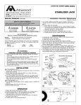
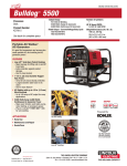
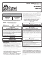
LITERATURE NUMBER MPD 85810 TELESCOPING STABILIZER 9 ENGLISH •Installation •Operation •Maintenance Effective 11/21/07 SAFETY ALERT SYMBOLS 3. Assemble drop tube (FIG 1-B) to 2.5˝ square housing (FIG 1-A) in a fully retracted position using lock pin (FIG 1-G). For 2˝ square, assemble drop tube to housing with the ball detent pin (FIG 1-F). Mount footpad with its length running from front to rear of the trailer. Safety Symbols alert you to potential personal safety hazards. Obey all safety messages following these symbols. WARNING avoid possible injury or death CAUTION NOTE: For your safety read all instructions before operating landing legs. Installer: Provide these instructions to the consumer. Consumer: Keep documents for future reference. OPERATION WARNING DO NOT EXCEED CAPACITY 2˝ SQUARE 3,000 LB. STABILIZER MAXIMUM VERTICAL LOAD MOVING PARTS CAN CRUSH OR CUT OR PINCH POINT 2.5˝ SQUARE 6,000 LB. • Keep hands and clothing away from moving parts. WARNING WARNING TRAILER CAN MOVE OR COLLAPSE • Never exceed the rated capacity. • STABILIZERS ARE NOT DESIGNED TO BE USED AS TRAILER JACKS. Do not use the stabilizer to lift or support the trailer during tire changes, axle work or trailer servicing (the trailer weight will exceed the capacity of the stabilizer). The stabilizer is designed to stabilize a portion of the trailer’s weight. Support the front end of the trailer with structural stands rated for the GVWR of the trailer. • The pin between the housing and drop tube should be the same diameter as the adjustment hole in the drop tube. Otherwise premature wear on drop tube and housing can occur. TRAILER CAN MOVE OR COLLAPSE • Never exceed rated capacity of stabilizer. • STABILIZERS ARE NOT DESIGNED TO BE USED AS TRAILER JACKS. Do not use the stabilizer to lift or support the trailer during tire changes, axle work or trailer servicing (the trailer weight will exceed the capacity of the stabilizer). The stabilizer is designed to stabilize a portion of the trailer’s weight. Support the front end of the trailer with structural stands rated for the GVWR of the trailer. • Chock both sides of trailer wheels before operating stabilizer. • All legs must touch the ground or the surface at the same time. • Retract stabilizer completely before towing trailer. INSTALLATION CAUTION CAUTION HAZARDOUS FUMES • SECURE TRAILER BEFORE TRAVELING • Before retracting, ensure there is no load on the stabilizer. Securely latch hitch before retracting stabilizer. • Lock pin spring clip must be positioned around stabilizer and secured over end of pin on opposite side of housing tube. This prevents pin from coming out during travel (FIG 1-G). • FOR 2.0˝ STABILIZER insure the ball detent pin is fully extended through the leg (FIG 1-F). Adequate ventilation must be provided when welding. WELDING INSTRUCTIONS • M.I.G. OR STICK • M.I.G. WELDING • STICK WELDING Optional spring-loaded pull pins (FIG 2-A Pull Pin or FIG 2-B on the 2.5˝ square stabilizer “SNAPS ”) are available to replace FIG 1G or F respectively. There must be a half-hole at the bottom of the housing in order to use the pull pin. If using a pull-pin, assemble it to the housing per its instruction manual. TM avoid possible injury and/or property damage - Attach with 3/16˝ fillet weld minimum. - Use A.W.S. ER 70S-3 or 6 wire or equivalent with a diameter of .035 - .045. The recommended shielding gas mixture is 75% - 95% Argon & 25% - 5% CO2. - Use E6011 A.W.S. welding rod or equivalent. Recommended machine settings for specific electrode diameters are as follows: 1/8˝ electrode set power between 115-130 Amps DC or 5/32” electrode set power between 140-160 Amps DC. TO EXTEND THE STABILIZER - Remove the pin in the drop tube or, if you have a pull pin that doesn’t remove, pull the handle pin so the pin is disengaged. Let the drop tube fall to the ground and re-pin in the nearest adjustment hole. TO RETRACT STABILIZER - Make sure there is no load on the stabilizer. Remove pin or disengage the pull pin and raise the drop tube, repinning it in the highest position. Fully retract the legs so that the foot pad is higher than the lowest point of the trailer, to prevent dragging while going over a curb. Before towing, check for maximum clearance between ground and bottom of stabilizer. 1. Weld two sides of housing to structural attachment point on trailer surface (FIG 3-A, 4-A & 4-B). Use a minimum of 4˝ of 3/16˝ fillet linear weld total on each side, stich or continuous (FIG 4-A & B). See welding instructions. When locating housing on trailer make sure access for lock pin is available for easy adjustment. 2. Assemble foot pad (FIG 1-D) to drop tube (FIG 1-B) with bridge pin clip (FIG 1-C) and clevis pin (FIG 1-E) for 2.5˝ square stabilizer. 1 MAINTENANCE PART IDENTIFICATION 1. Before use, inspect drop tube and inner housing tube. Replace if bent or damaged. PART NUMBERS ITEM 2. ONCE EACH YEAR: a. Extend stabilizer as far as possible, clean drop tube and housing tube. Coat exposed surface of tubes with silicone spray lubricant. Should problems or questions arise, contact your dealer, the trailer manufacturer or Atwood’s Service Department at 574-264-2131. 1-A 1-B 1-C 1-D 1-E 1-F 1-G 1 2˝ SQ 2.5˝ SQ DESCRIPTION 480921 480922 70269 70008 70325 480952 87186 70207 70216 70269 70008 70325 70215 N/S Housing Tube Drop Tube Bridge Pin Foot Pad Clevis Pin Ball Detent Pin Lock Pin 2 2.5" SQ 2.0" SQ (Tube du vérin) (Tube télescopique) (Goupille de pont) (Patin) (Goupille d'articulation) (Cheville à bille) (Goujon de blocage) A OR A G F B OPTIONAL Pull Pin FOR 2.5" SQ ONLY A F B C E 3 D D 4 A • WELD ON TWO SIDES OF HOUSING TUBE ON STRUCTURAL ATTACHMENT POINT ON TRAILER • USE A MINIMUM OF 4.0" OF WELD TOTAL, ON EACH SIDE (STICH OR CONTINUOUS) B • SEE WELDING INSTRUCTIONS • SOUDER LES DEUX CÔTÉS DU TUBE TÉLESCOPIQUE AU POINT D’ATTACHE STRUCTUREL SITUÉ SUR LA REMORQUE. • UTILISER UN MINIMUM DE 4,0 PO DE SOUDAGE AU TOTAL, DE CHAQUE CÔTÉ (ALTERNÉ OU CONTINU). • VOIR LES IN STRUCTIONS DE SOUDAGE 5.0" MAX (12,7 CM MAX) 1.0" RETRACTED (2,5 CM RENTRÉ) 17.0" EXTENDED (43,2 CM SORTI) A 2 A ATWOOD LIMITED WARRANTY HARDWARE SYSTEMS & COMPONENTS Atwood Mobile Products warrants to the original owner this product will be free of defects in material and workmanship for a period of two years from the date of purchase. Atwood’s liability hereunder is limited to the replacement of product, repair of product or replacement of product with a reconditioned product, at the discretion of the manufacturer. The warranty is void if the product has been damaged by accident, unreasonable use, neglect, tampering or other causes not arising from defects in material workmanship. The warranty extends to the original consumer purchaser of the product only, and is subject to the following conditions: 1. For two (2) year commencing with the date of purchase, Atwood will replace or repair any Hardware System & Components that are found to be defective by Atwood in material or workmanship. 2. In the event of a warranty claim, the owner must contact the Atwood Consumer Service Department, 1120 North Main St., Elkhart, IN 46514, Telephone: 574-264-2131 Fax: 574-206-9713. Warranty claim service must be performed as approved by the Atwood Consumer Service Department. Warranty replacement hardware systems and components or parts will be furnished freight prepaid. Labor cost to repair or replace will be limited to the amount of the original purchase price of the systems and components. The replaced warranty products or parts become the property of Atwood Mobile Products and must be returned to the Atwood Consumer Service Department freight prepaid, unless prior arrangements have been agreed to. 3. This limited warranty is valid only when the product is applied, installed, maintained and operated in accordance with this Atwood Installation, Maintenance and Operating Manual. Any deviation from these recommended specifications must be approved in writing by Atwood. 4. Any implied warranties are limited to the duration of this limited warranty as stated above. Atwood does not assume responsibility for consequential damage or loss, including loss of use of vehicle, loss of time, inconvenience, expense for gasoline, telephone, travel, lodging, loss or damage to personal properties, or loss of revenues. Some states do not allow limitations on how long an implied warranty lasts or limitations on consequential damages, so the above limitations may not apply to you. This limited warranty gives you specific legal rights which may vary from state to state.