1
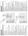
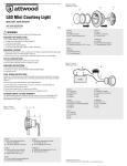
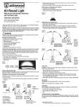
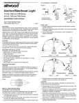
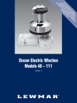
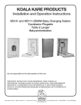
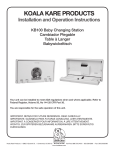
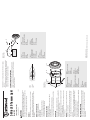
08-04
Two #8 stainless steel panhead screws
Phillips screwdriver
Marine grade caulk
Cordless drill; 1/8" (3mm) bit and 3/8" (9mm) bit
16-gauge wire and waterproof crimp connectors
Fuse holder (Attwood #14341) and 1-amp fuse
Connect to 12-Volt DC power source ONLY. All positive wires must be protected by
a 1-amp fuse. Higher voltage or failure to make proper wire and fuse connections
will void the product warranty. Use crimp type marine-grade connectors with
suitable insulation.
FINAL WIRING INSTRUCTIONS
4. Drill 3/8" (9mm) diameter hole for wire clearance and 1/8" (3mm) diameter holes
for mounting screws (Figure 2). Vertical or horizontal screw mounting pattern
may be used.
5. Bring one 16-gauge (+) and one (-) wire up through access hole DO NOT connect
these wires to power until you read FINAL WIRING INSTRUCTIONS. (Figure 3)
6. Connect wires using waterproof crimp connectors.
7. Caulk mounting holes and wire access holes.
8. Fasten assembly with two #8 stainless steel panhead screws. DO NOT OVERTIGHTEN.
Position wire access hole carefully, especially on aluminum boats,
so that wires do not contact the hull.
CAUTION:
1. To access light housing mounting holes, remove the bezel.
2. Place flat side of housing against a smooth vertical surface (see INSTALLATION
LOCATION for proper position). (Figure 2)
Important: Before drilling, be sure that light will shine straight astern and within 5°
of horizontal when boat is floating.
3. Use housing as a template to mark location of two mounting holes and a center
hole for wire access.
INSTALLATION
Transom Lights must be mounted:
• On the transom, exterior cabin bulkhead or superstructure. (Figure 1)
• As far aft as possible.
• On a vertical surface where the light will be unobstructed.
• So that light shines directly astern and horizontally when the boat is floating.
INSTALLATION LOCATION
•
•
•
•
•
•
REQUIRED FOR INSTALLATION
6556 Transom Light meets USCG CFR 183.810, ABYC A-16 requirements,
and all applicable standards as tested by Imanna Labs, 11/30/2007. 2 nautical
mile visibility.
These Attwood Transom Lights are for use on boats up to 65.6 ft. (20 meters).
FEATURES
Use only the fuse amperage rating specified in these instructions.
Read all instructions carefully before installing and using this product. To prevent
personal injury, disconnect the power source when installing or servicing this
product. Always remove the boat from the water before using 120V AC power tools.
WARNING
Form Number 69437 Rev. A
SAVE THESE INSTRUCTIONS
Model 6556
2-Mile LED Transom Light
Figur 2
A. 3 mm håldiam.
B. hus
C. infattning
D. fästskruvar
Abbildung 2
A. Löcher 3 mm
B. Gehäuse
C. Abdeckung
D. Montageschrauben
D
Figura 2
A. Orificios de 1/8" (3 mm) de diámetro
B. Bastidor
C. Bisel
D. Tornillos de instalación
B
Figure 2
A. Trous de 3 mm de diamètre
B. Boîtier
C. Cadran
D. Vis de montage
A
Figure 2
A. 1/8" (3mm) Diameter Holes
B. Housing
C. Bezel
D. Mounting Screws
Figure 3 / Figura 3
Abbildung 3 / Figur 3
Figure 1
Figura 1
Abbildung 1
Figur 1
C
Because of the longevity of Attwood’s LED lighting technology, Attwood offers
a limited 10-year warranty on this LED lighting product. See Product Catalog or
attwoodmarine.com for details.
ATTWOOD LIMITED 10-YEAR WARRANTY
1. Neatly thread wires to the switch, avoiding areas where abrasion or snagging
may occur.
2. Use switch (Attwood #14386 or equivalent) that allows two-position ON/OFF/ON
operation – one for running lights, and one for anchor lights. Attach wires with
crimp-on butt joint connectors. Test lights for proper operation.
E
A
D
Abbildung 3
A. Sicherung 1 A
B. 3-Weg-Schalter
C. pos.
D. neg.
E. 12 V Gleichstrom
Figure 3
A. Fusible de 1 ampère
B. Interrupteur à trois positions
C. pos.
D. nég.
E. 12 volts CC
D
C
B
© 2008 Attwood Corporation
1016 N. Monroe Street, Lowell, MI 49331-0260 www.attwoodmarine.com
Figur 3
A. 1 A säkring
B. 3-vägs strömbrytare
C. pos
D. neg
E. 12 V likström
Figura 3
A. Fusible de 1 amperio
B. Interruptor de 3 vías
C. positivo
D. negativo
E. 12 voltios de CC
Figure 3
A. 1-Amp Fuse
B. 3-Way Switch
C. Pos.
D. Neg
E. 12V DC
C
Figure 3 / Figura 3
Abbildung 3 / Figur 3
ELEMENTOS NECESARIOS PARA LA INSTALACION
•
•
•
•
•
•
REQUIS POUR L’INSTALLATION
•
•
•
•
•
•
INSTALACION
1. Para acceder a los orificios de instalación del bastidor de la luz, retire el bisel.
2. Ubique el lado plano del bastidor en contra de la superficie vertical lisa (ver UBICACION DE LA
INSTALACION para conocer la posición correcta). (Figura 2)
Importante: Antes de perforar, asegúrese de que la luz alumbrará en línea recta hacia atrás y en
un nivel horizontal de 5° cuando el bote está flotando.
3. Use un bastidor como plantilla para marcar la ubicación de los dos orificios de instalación y un
orificio central para el paso del cable.
PRECAUCION: Coloque con cuidado el orificio de acceso para el cable, especialmente sobre
INSTALLATION
1. Pour accéder aux trous de montage du boîtier d’éclairage, retirez le cadran.
2. Placez le côté plat du boîtier contre une surface verticale lisse (reportez-vous à l’EMPLACEMENT
D’INSTALLATION pour connaître la bonne position) (figure 2).
Important : Avant de percer, assurez-vous que le feu brillera directement vers l’arrière et à un
angle de 5° de l’horizontal lorsque le bateau flotte.
3. Utilisez le boîtier comme gabarit pour marquer l’emplacement des deux trous de montage et
d’un trou central pour l’accès des fils.
MISE EN GARDE :
À cause de la longévité de la technologie des feux à DEL d’Attwood, Attwood offre une garantie
limitée de dix ans sur ce produit d’éclairage à DEL. Reportez-vous au catalogue de produits ou à
attwoodmarine.com pour de plus amples renseignements.
GARANTIE LIMITÉE DE DIX ANS D’ATTWOOD
Reliez à une source d’alimentation à CC de 12 volts SEULEMENT. Tous les fils positifs doivent
être protégés par un fusible d’un ampère. Une tension supérieure ou l’omission d’effectuer les
connexions de fils et de fusibles appropriées annuleront la garantie du produit. Utilisez des
connecteurs à sertir de qualité marine avec une isolation appropriée.
1. Filetez les fils proprement jusqu’à l’interrupteur en évitant les zones où de l’abrasion ou des
accrocs peuvent se produire.
2. Utilisez un interrupteur (Attwood n° 14386) qui permet un fonctionnement à deux positions
MARCHE/ARRÊT/MARCHE - une pour les feux de navigation et une pour les feux de mouillage.
Attachez les fils avec des connecteurs à sertir par raccordement en about. Vérifiez que les feux
fonctionnent correctement.
DIRECTIVES DE CÂBLAGE FINALES
Debido a la antigüedad de la tecnología de iluminación con LED de Attwood, Attwood ofrece
una garantía limitada de 10 años para este producto de iluminación con LED. Consulte el
catálogo del producto o visite attwoodmarine.com para conocer los detalles.
GARANTIA LIMITADA DE 10 AÑOS DE ATTWOOD
Conecte únicamente a 12 voltios de CC. Todos los cables positivos deben estar protegidos
por un fusible de 1 amperio. Un voltaje más elevado o la imposibilidad de realizar conexiones
correctas de cables y fusibles invalidarán la garantía del producto. Use conectores de grado
náutico de engarce con el aislamiento adecuado.
1. Enrosque prolijamente los cables al interruptor evitando las áreas donde se pueden producir
abrasiones o enganches.
2. Use un interruptor (Attwood No. 14386 o equivalente) que permita dos posiciones de
funcionamiento, ENCENDIDO/APAGADO, una para las luces de funcionamiento y otra
para las luces del ancla. Fije los cables con conectores con juntas en los extremos para
engarzar. Pruebe las luces para verificar su correcto funcionamiento.
INSTRUCCIONES PARA EL CABLEADO FINAL
botes de aluminio, de modo que los cables no toquen el casco.
4. Perfore un orificio de 3/8" (9 mm) de diámetro de espacio para el cable y orificios de 1/8" (3 mm)
de diámetro para los tornillos de instalación (Figura 2). Se puede usar un modelo de instalación
de tornillo horizontal o vertical.
5. Pase un cable calibre 16 (+) y otro (-) por el orificio de acceso. NO conecte estos cables a la
electricidad hasta que haya leído las INSTRUCCIONES PARA EL CABLEADO FINAL. (Figura 3)
6. Conecte los cables con los conectores de engarce impermeables.
7. Coloque masilla para calafatear en los orificios de instalación y en los de acceso del cable.
8. Ajuste la unidad con los dos tornillos cilíndricos de acero inoxidable de cabeza troncocónica
No. 8. NO AJUSTE EXCESIVAMENTE.
Las luces de bovedilla se deben instalar de la siguiente manera:
• En la bovedilla, en el panel con acabado o en la superestructura de la cabina exterior (Figura 1).
• Lo más alejado de la popa posible.
• En una superficie vertical donde no se obstruirá la luz.
• De manera que la luz brille directamente hacia atrás y horizontalmente cuando el bote esté flotando.
Les feux de tableau doivent être installés :
• sur le tableau, le pontage de la cabine extérieure ou la superstructure (figure 1);
• aussi loin que possible;
• sur une surface verticale où le feu ne sera pas obstrué;
• de façon à ce que le feu brille directement vers l’arrière et horizontalement lorsque le bateau flotte.
Positionnez le trou d’accès des fils soigneusement, particulièrement
sur les bateaux en aluminium, de manière à ce que les fils n’entrent pas en contact avec la coque.
4. Percez un trou de 9 mm de diamètre pour les fils et des trous de 3 mm de diamètre pour les
vis de montage (figure 2). Un motif de montage des vis horizontal ou vertical peut être utilisé.
5. Faites passer un file de calibre 16 (+) et un fil (-) dans le trou d’accès. NE reliez PAS ces fils à
l’alimentation avant d’avoir lu les DIRECTIVES DE CÂBLAGE FINALES (figure 3).
6. Reliez les fils au moyen de connecteurs à sertir à l’épreuve de l’eau.
7. Calfeutrez les trous de montage et les trous d’accès des fils.
8. Fixez avec deux vis à tête cylindrique bombée n° 8 en acier inoxydable. NE SERREZ PAS TROP.
UBICACION DE LA INSTALACION
EMPLACEMENT D’INSTALLATION
Dos tornillos cilíndricos de acero inoxidable de cabeza troncocónica No. 8
Destornillador Phillips
Masilla para calafatear de grado náutico
Taladro inalámbrico; broca de 1/8" (3 mm) y de 3/8" (9 mm)
Cable calibre 16 y conectores de engarce impermeables
Portafusibles (Attwood No. 14341) y fusible de 1 amperio
Estas luces de bovedilla de Attwood son para usar en botes de hasta 20 metros.
Las luces de bovedilla 6556 cumplen con las normas USCG del CFR 183.810, los requisitos
ABYC A-16 y todas las normas aplicables según las pruebas realizadas por Imanna Laboratory,
11/30/07. Visibilidad de 2 millas náuticas.
Ces feux de tableau Attwood sont conçus pour être utilisés sur les bateaux mesurant jusqu’à 20 mètres.
Le feu de tableau est conforme aux exigences USCG CFR 183.810, ABYC A-16 et à toutes les
normes applicables selon les tests d’Imanna Labs effectués le 30 novembre 2007. Visibilité de
deux miles nautiques.
Deux vis à tête cylindrique bombée n° 8 en acier inoxydable
Tournevis cruciforme
Mastic isolant de qualité marine
Perceuse sans fil; mèches de 3 et 9 mm
Fil de calibre 16 et connecteurs à sertir à l’épreuve de l’eau
Porte-fusible (Attwood n° 14341) et un fusible d’un ampère
CARACTERISTICAS
CARACTÉRISTIQUES
ADVERTENCIA
Lea atentamente todas las instrucciones antes de instalar y utilizar este producto. Para evitar
lesiones personales, desconecte la fuente de energía cuando instale o repare este producto.
Retire el bote del agua antes de usar herramientas eléctricas de 120 voltios de CA.
Utilice únicamente el amperaje del fusible especificado en estas instrucciones.
Lisez toutes les directives attentivement avant d’installer et d’utiliser ce produit. Pour éviter toute
blessure, débranchez la source d’alimentation lors de l’installation ou de la réparation de ce
produit. Sortez toujours le bateau de l’eau avant d’utiliser tout outil électrique de 120 volts CA.
Utilisez seulement l’intensité en ampère précisée dans ces directives.
AVERTISSEMENT
CONSERVE ESTAS INSTRUCCIONES
Número de formulario 69437 Rev. A
CONSERVEZ CES DIRECTIVES
Formulaire numéro 69437 Rév. A
08-04
Modelo 6556
Modèle 6556
08-04
Luz de bovedilla con LED de 2 millas
Feu de tableau à DEL de trois kilomètres
08-04
Zwei Kreuzschlitz-Kegelkopf-Montageschrauben Nr. 8 aus rostfreiem Stahl
Kreuzschlitz-Schraubendreher
Für den Gebrauch auf Booten zugelassene Dichtungsmasse
Akku-Bohrmaschine mit 3 mm und 9 mm Bohrer
Elektrodraht mit 1,5 mm2 Querschnitt und wasserdichte Crimp-Steckverbinder
Sicherungshalter (Attwood Nr. 14341) und Sicherung (1 A)
Wegen der langen Lebensdauer der LED-Leuchtentechnologie von Attwood gewährt Attwood
eine eingeschränkte 10-jährige Garantie auf diese LED-Leuchte. Einzelheiten siehe Produktkatalog
oder attwoodmarine.com.
EINGESCHRÄNKTE 10-JÄHRIGE GARANTIE VON ATTWOOD
AUSSCHLIESSLICH an eine 12 V Stromquelle anschließen. Im positiven Teil des Stromkreises
muss eine 1 A Sicherung eingebaut werden. Eine höhere Spannung oder falscher Anschluss der
Drähte oder der Sicherung bringen die Produktgarantie zum Erlöschen. Verwenden Sie für den
Einsatz auf Booten zugelassene Crimp-Steckverbinder mit der passenden Isolierung.
1. Verlegen Sie die Drähte zum Schalter so, dass Bereiche, in denen sie aufgescheuert werden
oder sich verhängen könnten, vermieden werden.
2. Verwenden Sie einen Schalter (Attwood Nr. 14386 oder entsprechenden), welcher einen
Betrieb EIN / AUS / EIN gestattet: Eine Position für das Fahrlicht und eine für das Ankerlicht.
Schließen Sie die Drähte mit anzucrimpenden Stumpfsteckverbindern an. Überprüfen Sie die
Leuchte auf die richtige Funktion.
ENDGÜLTIGE VERDRAHTUNGSANLEITUNG
Positionieren Sie das Loch zur Durchführung der Drähte - besonders auf
Aluminium-Booten - sehr sorgfältig, so dass die Drähte den Rumpf nicht berühren werden.
4. Für die Durchführung der Drähte bohren Sie ein Loch mit 9 mm Durchmesser, für die
Montageschrauben zwei Löcher mit 3 mm Durchmesser (Abbildung 2). Die Montagelöcher
können sowohl horizontal als auch vertikal angebracht werden.
5. Bringen Sie jeweils einen Elektrodraht mit 1,5 mm2 Querschnitt für den positiven und
negativen Anschluss durch das Durchgangsloch (Abbildung 3).
6. Schließen Sie die Drähte mit wasserfesten Crimp-Steckverbindern an.
7. Dichten Sie die Montagelöcher und das Durchgangsloch für die Drähte ab.
8. Befestigen Sie die Baugruppe mit zwei Kreuzschlitz-Kegelkopf-Montageschrauben Nr. 8 aus
rostfreiem Stahl. ZIEHEN SIE DIE SCHRAUBEN NICHT ZU FEST AN.
VORSICHT:
1. Damit die Montagelöcher des Gehäuses der Leuchte zugänglich werden, entfernen Sie
die Abdeckung.
2. Halten Sie die flache Seite des Gehäuses gegen die glatte, senkrechte Wand (siehe
INSTALLATIONSORT für die richtige Positionierung) (Abbildung 2).
Wichtig: Bevor Sie die Löcher zu bohren beginnen, stellen Sie sicher, dass das Licht mit einer
horizontalen Abweichung von maximal 5° direkt nach achtern scheint, wenn das Boot im Wasser ist.
3. Verwenden Sie das Gehäuse als Vorlage, um die Stelle der beiden Montagelöcher und des
mittleren Lochs zur Durchführung der Drähte zu markieren.
INSTALLATION
Heckleuchten müssen folgendermaßen angebracht werden:
• Am Heckspiegel, außen an der Kabinenwand oder dem Heckaufbau (Abbildung 1).
• So weit hinten wie möglich.
• Auf einer senkrechten Oberfläche, wo das Licht nicht abgedeckt werden kann.
• In der Art und Weise, dass das Licht direkt horizontal nach achtern scheint, wenn das Boot schwimmt.
INSTALLATIONSORT
•
•
•
•
•
•
FÜR DIE INSTALLATION SIND NOTWENDIG:
Diese Heckleuchten von Attwood werden in Booten bis zu 20 m Länge eingesetzt.
Die Heckleuchte Modell 6556 erfüllt die Anforderungen nach USCG CFR 183.810, ABYC A-16
und alle anwendbaren Normen. Dies wurde von den Imanna Labs am 30. 11. 2007 überprüft.
Sichtbar auf 2 nautische Meilen (3,6 km).
EIGENSCHAFTEN
Bevor Sie dieses Produkt installieren und verwenden, lesen Sie bitte die gesamte Anleitung
sorgfältig durch. Um Verletzungen zu vermeiden, trennen Sie beim Installieren oder bei
der Wartung das Gerät von der Stromquelle. Bevor Sie ein mit Netzspannung betriebenes
Elektrowerkzeug einsetzen, bringen Sie das Schiff aus dem Wasser.
Setzen Sie nur eine Sicherung mit dem in dieser Anleitung angegebenen Wert ein.
WARNUNG
BEWAHREN SIE DIESE ANLEITUNG AUF.
Dokumentennummer 69437 Rev. A
Modell 6556
2-Meilen LED Heckleuchte
08-04
två rostfria skruvar (nr 8) med koniska huvuden
stjärnskruvmejsel
tätningsmedel för marint bruk
sladdlös borrmaskin; 3 och 9 mm borrbits
16-gauge kabel och vattentäta krimpkontakter
säkringshållare (Attwood nr 14341) och 1 A säkring
På grund av den långa livslängd som Attwoods lysdiodlampteknik möjliggör, erbjuder Attwood
en begränsad garanti på 10 år för denna lysdiodbelysningsprodukt. Se produktkatalogen eller
attwoodmarine.com för fler detaljer.
ATTWOODS BEGRÄNSADE 10-ÅRSGARANTI
Anslut ENBART till en 12 V likströmskälla. Alla positiva kablar måste skyddas av en 1 A säkring.
Högre spänningar eller felaktiga kabel- och säkringsanslutningar gör att produktgarantin upphävs.
Använd krimpkontakter för marint bruk med lämplig isolering.
1. Dra kablarna på ett snyggt sätt till strömbrytaren så att de inte kan skavas eller fastna.
2. Använd en strömbrytare (Attwood nr 14386 eller motsvarande) som möjliggör
tvålägesfunktion (PÅ/AV/PÅ) – ett för gångljus och ett för ankarlanternor. Anslut kablarna
med hjälp av krimpstötskarvskontakter. Kontrollera att lamporna fungerar som avsett.
ANVISNINGAR FÖR SLUTLIG KOPPLING
Placera kabelhålet noggrant, särskilt på aluminiumbåtar, så att kablarna
inte vidrör skrovet.
4. Borra ett hål med 9 mm diameter för kablarna och hål med 3 mm diameter för fästskruvarna
(figur 2). En vertikal eller horisontell skruvplacering kan väljas.
5. För en 16-gauge (+) kabel och en negativ kabel (-) upp genom kabelhålet. Anslut INTE dessa
kablar till strömkällan förrän du har läst igenom ANVISNINGAR FÖR SLUTLIG KOPPLING.
(figur 3)
6. Anslut kablarna med hjälp av vattentäta krimpkontakter.
7. Täta monterings- och kabeldragningshålen med tätningsmedel.
8. Fäst enheten med två rostfria skruvar (nr 8) med koniska huvuden. SPÄNN INTE ÅT FÖR HÅRT.
VAR FÖRSIKTIG!
1. Avlägsna infattningen för att komma åt lamphusets monteringshål.
2. Placera husets flata sida mot ett jämnt och vertikalt underlag (se MONTERINGSSTÄLLE
för rätt placering). (figur 2)
Viktigt! Innan du borrar, säkerställ att lampan kommer att lysa rakt akterut inom 5° från
horisontalplanet då båten flyter.
3. Använd huset som mall för att markera de två monteringshålens placering samt ett mitthål
för kabeldragningen.
MONTERING
Akterspegellampor måste monteras:
• På akterspegeln, yttre hyttskottet eller överbyggnaden. (figur 1)
• Så långt akterut som möjligt.
• På en vertikal yta där lampan inte skyms.
• Så att lampan lyser rakt akterut och horisontellt då båten flyter.
MONTERINGSSTÄLLE
•
•
•
•
•
•
DETTA KRÄVS FÖR INSTALLATIONEN
Dessa Attwood-akterspegellampor är avsedda för båtar upp till 65,6 fot (20 meter).
Akterspegellampan 6556 uppfyller kraven i USCG CFR 183.810, ABYC A-16, samt alla tillämpliga
standarder vid utprovningen av Imanna Labs, 2007-11-30. Syns på 2 sjömils avstånd.
EGENSKAPER
Läs alla anvisningar noggrant innan denna produkt monteras och används. Koppla bort
strömkällan när denna produkt monteras eller underhålls för att förhindra personskador.
Avlägsna alltid båten från vattnet innan 240-volts elverktyg används.
Använd enbart det säkringsamperetal som specificeras i de här anvisningarna.
VARNING!
SPARA DESSA ANVISNINGAR
Formulärnummer 69437 rev. A
Modell 6556
"2-mile"-lysdiodlampa för akterspegel