1
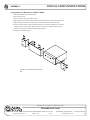
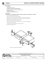
AARMK2-5
INSTALLATION INSTRUCTIONS
Kit Contains:
•
•
•
•
•
•
•
•
(2)
(4)
(1)
(2)
(2)
(2)
(4)
(4)
Rack Ears
Rack Ear Chassis Screws
Rack Extension Plate for Single Unit Mounting
Screws to Combine Extension Plate to Rack Ear
Nuts to Secure Screws to Extension Plate and Rack Ear
Bottom Joiner Plates
Bottom Joiner Plate Screws
Rack Rail Screws with Plastic Washers
Instructions:
Configuration #1 - Mounting two AA35 or PA601 amplifiers or one AA35 with a PA601
1. Disconnect amplifier from electrical source.
2. Remove the four feet from the bottom of each unit.
3. Align and secure the two joiner plates to the bottom of units with the enclosed screws.
Note: Both plates must be attached, one towards the front and one towards the back.
4. Remove front two screws from the sides of the amps.
5. Align the enclosed rack ear to these chassis holes.
6. Use the enclosed chassis screws to attach the rack ears to either side of the amplifiers.
Secure firmly, do not over tighten.
7. Install into rack using rack rail screws and washers provided.
8. Disregard any additional pieces.
R
PL EAR
AT
E
FR
PL ONT
AT
E
Illustration 1: Rack Mounting Two Amplifiers
Specifications are subject to change without notice
AtlasSound.com
1601 JACK MCKAY BOULEVARD ENNIS, TEXAS 75119 U.S.A. •
©2006 ATLAS SOUND LP
Printed in U.S.A.
00406
TELEPHONE: (800) 876-3333 • FAX: (800) 765-3435
ATS002329 RevA 04/06
PP
AARMK2-5
INSTALLATION INSTRUCTIONS
Configuration #2 - Mounting one AA35 or PA601
1. Disconnect amplifier from electrical source.
2. Remove the four feet.
3. Remove front two screws from sides of amp.
4. Align and secure the chassis extension plate to a rack ear using the enclosed screws and nuts.
5. Align the rack ear and extension assembly to the chassis holes on the side of the amp.
6. Use the enclosed chassis screws to attach the rack ear and extension assembly to the chassis.
Secure firmly, do not over tighten. Attach the other rack ear to the opposite side of the amp.
7. Install into rack using rack rail screws and washers provided.
8. Disregard any additional pieces.
Illustration 2: Rack Mounting One Amplifier
Specifications are subject to change without notice
AtlasSound.com
1601 JACK MCKAY BOULEVARD ENNIS, TEXAS 75119 U.S.A. •
©2006 ATLAS SOUND LP
Printed in U.S.A.
00406
TELEPHONE: (800) 876-3333 • FAX: (800) 765-3435
ATS002329 RevA 04/06
PP