1
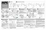
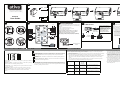
2 CONNECT BATTERY CARTRIDGE
1 CONTENTS
RJ-11
RJ-45
RJ-11
RJ-45
USB
RJ-45
Coax
Coax
1
2
516-015
User Guide
3 OPERATING ENVIRONMENT
Æ
ATIVA
User Guide
53 CHECK BUILDING WIRING
4 CONNECT EQUIPMENT / POWER
FAULT INDICATOR
Fax
32 - 104oF (0 - 40oC)
Printer or Scanner
Computer
If the rear panel Building Wiring Fault (red) indicator is lit,
a potential shock hazard exists due to one of the following
conditions:
• Open or high resistance ground
• Hot and Neutral polarities are reversed
• Overloaded neutral circuit
Improper building wiring should be corrected by a
qualified electrician. Do not use the UPS until the
condition that caused the fault is corrected.
Note: Improper building wiring will not prevent the UPS
from operating, but it will limit its protection capability.
6 CONNECT MODEM/PHONE/FAX and
TVSS Ground
RJ-45/
RJ-11
Phone
Jack
External Disk or
CD / DVD Drive
Monitor
RJ-45/
RJ-11
RJ-45/
RJ-11
From stand alone
data line surge
suppressor or
electronic device
If needed, the UPS features a
TVSS ground screw for
connecting the ground lead of
any additional stand alone surge
suppression devices, such as an
ProtectNet product; or any
electronic device with an
external ground connection.
RJ-45/
RJ-11
Computer
Modem Port
7 SWITCH ON THE UPS
Note: Allow the UPS to charge for a full or 24 hours prior
to use.
Press the front panel Power ON/OFF switch and observe
that the following events occur after pressing and
releasing the switch:
• The blue On Line indicator flashes.
• The yellow On Battery indicator lights while a SelfTest is being performed.
• When Self-Test has successfully completed, only the
blue On Line indicator will be lit.
• If the internal battery cartridge is not connected (see
Step 2 above), the blue On Line indicator, and red
Replace Battery indicators will light. The UPS will
also emit a chirping sound.
OR
Phone or Fax
ON LINE
CABLE IN
ON BATTERY
OVERLOAD
CABLE OUT
To 120 VAC Wall Outlet
STATUS INDICATORS, ALARMS and CIRCUIT BREAKER
There are four status indicators (lights) on the front panel of the UPS (On
Line, On Battery, Overload, and Replace Battery).
On Line
Four Beeps Every 30 Seconds - this alarm is sounded whenever the UPS is running
On Battery. Consider saving work in progress.
Continuous Beeping - this alarm is sounded whenever a low battery condition is
reached. Battery run-time is very low. Promptly save any work in progress, and exit
all open applications. Shut down the operating system, computer and the UPS.
On Battery
Overload
Continuous Tone - this alarm is sounded whenever the Battery Backup outlets are
overloaded.
Replace Battery
Chirps for 1 Minute Every 5 Hours - this alarm is sounded whenever the battery
has failed the automatic diagnostic test.
On Line (blue) - is lit whenever utility power is powering the Battery
Backup outlets.
On Battery (yellow) - is lit whenever the battery of the UPS is powering
equipment connected to the Battery Backup Outlets.
Overload (red) - is lit or flashing whenever power demand has exceeded
the capacity of the UPS.
Replace Battery (red) - is lit whenever the battery is near the end of its
useful life, or if the battery is not connected (see above). A battery that is
near the end of its useful life has insufficient run-time and should be
replaced.
Circuit Breaker - the circuit breaker button located on the rear panel of the UPS will
stick out if an overload condition forces the UPS to disconnect itself from utility
power. If the button sticks out, disconnect non-essential equipment. Reset the circuit
breaker by pushing the button inward.
Building
Wiring
Fault
REPLACE BATTERY
Building Wiring Fault
Indicator
TRANSFER VOLTAGE and SENSITIVITY ADJUSTMENT
In situations where the UPS or connected equipment appears too sensitive to input voltage, it may be
necessary to adjust the transfer voltage. This is a simple task requiring use of the front panel push
button. To adjust the transfer voltage, proceed as follows:
1. Plug the UPS into the utility power source but do not turn the unit on. The UPS will be in Standby
Mode (no indicators lit).
2. Press and hold the front panel ON/OFF switch fully inward for 10 seconds, until all LED
indicators on the UPS flash to acknowledge it has entered Programming Mode. Release the ON/
OFF button, and the UPS's LEDs will flash per table below, indicating it's current sensitivity
setting.
Note: the UPS automatically exits programming mode in 5 seconds if no buttons are pressed.
3. Use the table below to decide which Sensitivity setting is desired.
Indicators
Flashing
Sensitivity
Setting
Input Voltage
Range
(for utility
operation)
Use When
1
(yellow)
Low
78 - 142 Vac
Input voltage is extremely low or
high. Not recommended for computer
loads.
2
(yellow, and red)
Medium
(factory
default)
88 - 139 Vac
UPS frequently goes On Battery.
3
(yellow, red, and
red)
High
88 - 136 Vac
Connected equipment is sensitive to
voltage fluctuations.
4. To select the Low Sensitivity setting, press and hold the ON/OFF switch
for 1-2 seconds (until a beep is heard). Upon release, the yellow indicator
will flash, indicating Low Sensitivity.
5. To select the Medium Sensitivity setting (the unit's default), press and
hold the ON/OFF switch for 1-2 seconds (until beep is heard). Upon
release, the yellow indicator will flash. Press and hold the ON/OFF
button again for 1-2 seconds (until beep is heard). Upon release, the
yellow and one red indicator will flash, indicating Medium Sensitivity.
6. To select the High Sensitivity setting, press and hold the ON/OFF switch
for 1-2 seconds (until beep is heard). Repeat this two more times. Upon
final release, the yellow and two red indicators (bottom three indicators)
will flash, indicating High Sensitivity.
7. The UPS will automatically exit Programming Mode in five seconds,
and is ready for use.
990-2491
SPECIFICATIONS
TROUBLESHOOTING
Problem
UPS will not switch on.
Possible Cause
Item
Corrective Action
UPS not connected to AC power source.
Ensure the UPS is securely connected to an AC outlet.
On-line Input Voltage Range
(default settings)
UPS circuit breaker “tripped”.
Disconnect non-essential equipment from the UPS. Reset (push in)
the rear panel circuit breaker. Switch on the UPS and plug in devices
one at a time. If the circuit breaker trips again, disconnect the device
that caused the breaker to trip.
Automatic Voltage Regulation (AVR)
Connect battery cartridge (see Connect Battery Cartridge).
Maximum Load
Consider adjusting the transfer voltage and sensitivity. See Transfer
Voltage and Sensitivity Adjustment.
Typical Recharge Time
Internal battery is not connected.
Utility input voltage quality is out of range.
On-line Frequency Range
On-battery Waveshape
The UPS's plug has partially pulled out of the wall
outlet, wall outlet has been turned off, or its circuit
breaker has tripped.
Verify the UPS's plug is fully inserted into the wall, and that power
is present at the wall outlet.
Unit is in the midst of performing an automatic self
test.
No action is necessary.
Size (H x W x D)
Utility input voltage is out of range, frequency is out
of range or the wave form is distorted.
Consider adjusting the transfer voltage and sensitivity. See Transfer
Voltage and Sensitivity Adjustment.
Weight
UPS is heavily loaded.
Unplug non-essential equipment (printers, scanners, etc.) from the
Battery Backup outlets and plug into 'Surge Only' outlets.
EMI Classification
UPS battery cartridge is discharged due to recent
power outage and has not had time to recharge.
Charge the battery cartridge for 24 hours. UPS runtime is reduced
until the battery cartridge is fully charged.
Battery has reached the end of its life.
Replace battery cartridge (see Order Replacement Battery
Cartridge).
Operating / Storage Relative Humidity
Refer to Replace Battery Cartridge, and replace the battery cartridge.
Connected equipment is drawing more power than
the UPS can provide.
Move one or more equipment power plugs from Battery Backup
outlets to Surge Only outlets.
Blue On Line indicator is on and all
other front panel indicators are
flashing.
Internal UPS fault.
Contact Ativa Technical Support (see Ativa Contact Information).
Stepped Sine Wave
720 W
24 Hours
23o to 113oF
-5o to 45oC
UPS operates on battery although
utility power exists.
Battery has reached the end of its life.
+12% (Boost Only)
57 - 63 Hz (Autosensing)
Storage Temperature
Unplug device from 'Surge Only' outlet and move to a 'Battery
Backup' outlet.
Red Overload indicator is on or
flashing.
88 - 139 VAC
32o to 104oF
0o to 40oC
Equipment was plugged into a Surge Only outlet.
Red Replace Battery indicator is on.
1200 VA
Operating Temperature
UPS does not power essential
equipment during an outage.
UPS does not provide expected
backup time.
LIMITED TWO YEAR PRODUCT WARRANTY
Shipping Weight
Approvals
0 to 95% non-condensing
8.7 inch X 5.1 inch X 13.8 inch
220 mm X 130 mm X 350 mm
29.7 lbs (13.5 kg)
33.2 lbs (15.1 kg)
ODP PROVIDES THIS LIMITED WARRANTY IN LIEU OF ALL OTHER
WARRANTIES EITHER EXPRESS OR IMPLIED. EXPRESSLY EXCLUDED ARE ALL
WARRANTIES OF FITNESS FOR A PARTICULAR PURPOSE OR
MERCHANTABILITY. ODP’S SOLE OBLIGATION AND THE USER’S EXCLUSIVE
REMEDY UNDER THIS WARRANTY SHALL BE LIMITED TO THE REPAIR OR
REPLACEMENT AT ODP’S SOLE DESCRETION AND COST, OF PRODUCT OR
COMPONENTS.
IN NO EVENT SHALL ODP, ITS AFFILIATES, SUBSIDIARIES, SUPPLIERS OR
PARENT COMPANIES BE RESPONSIBLE FOR CONSEQUENTIAL, SPECIAL, OR
INCIDENTIAL DAMAGES ARISING OUT OF A CLAIM OF DEFECTIVE PRODUCT
EVEN IF ODP HAS BEEN ADVISED OF THE POSSIBILITY OF SUCH DAMAGES.
FCC / DOC Class B Certified
TUV C-US certified per UL 1778, CSA 22.2
No. 107.1, and NOM-001
Notice: This device complies with part 68 and part 15 of the FCC rules. Operation is
subject to the following two conditions: (1) This device may not cause harmful
interference. (2) This device must accept any interference received, including interference
that may cause undesired operation.
Note: This equipment has been tested and found to comply with the limits for Class B
digital devices, pursuant to part 15 of the FCC Rules. These limits are designed to provide
reasonable protection against harmful interference in a residential installation. This
equipment generates, uses and can radiate radio frequency energy and, if not installed and
used in accordance with the instructions, may cause harmful interference to radio or
television reception, which can be determined by turning the equipment off and on. The
user is encouraged to try to correct the interference by one or more of the following
measures:
• Reorient or relocate the receiving antenna.
• Increase the separation between the equipment and the receiver.
• Connect the equipment into an outlet on a circuit different from that to which the
receiver is connected.
• Consult the dealer or an experienced radio/TV technician for help.
REPLACE BATTERY CARTRIDGE
The limited warranty covers the original purchase of a new product used for normal
commercial, personal or household use. Office Depot, Inc. (ODP) warrants its products will
be free from defects in materials and workmanship (normal wear and tear excepted) for two
(2) years from the date of purchase, except as provided below. ODP, at its option, will
replace with a comparable product, free of charge, any product which fails under normal use
as a result of such defect. This warranty does not apply to damage caused by fire, accident,
negligence, misuse, improper cleaning or other circumstances not directly attributable to
manufacturing defects.
SOME STATES OR PROVINCES DO NOT ALLOW THE EXCLUSION OF IMPLIED
WARRANTIES OR LIMITATIONS ON HOW LONG AN IMPLIED WARRANTY
LASTS OR THE EXCLUSION OR LIMITATION OF INCIDENTIAL OR
CONSEQUENTIAL DAMAGES, SO THE ABOVE LIMITATIONS MAY NOT APPLY
TO YOU. THIS WARRANTY GIVES YOU SPECIFIC LEGAL RIGHTS, AND YOU
MAY ALSO HAVE OTHER RIGHTS WHICH MAY VARY BY STATE OR PROVINCE.
THIS WARRANTY APPLIES ONLY TO THE U.S. AND CANADA.
ATIVA CONTACT INFORMATION
For Technical Support and Returns, please call:
1-877-777-HELP (1-877-777-4357)
On the bottom of this equipment is a label that contains, among other information, the
FCC registration number and ringer equivalence number (REN) for this equipment. If
requested, this information must be provided to the telephone company.
Modifications not approved by the party responsible for compliance could void user’s
authority to operate the equipment.
1
2
990-2491