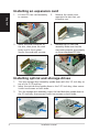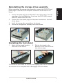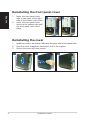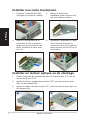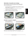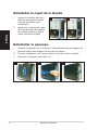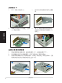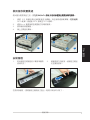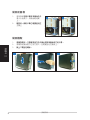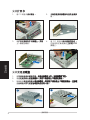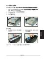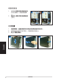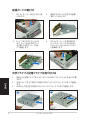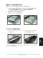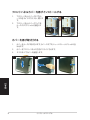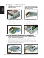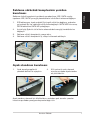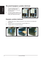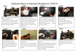
1
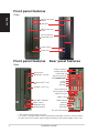
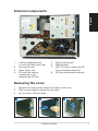
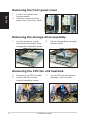
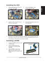
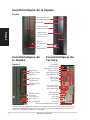
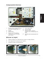
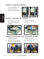
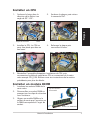
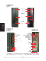
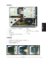
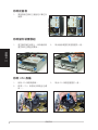
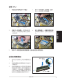
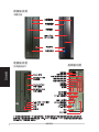
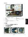
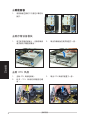
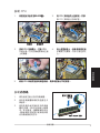
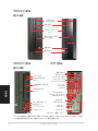
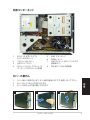
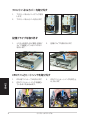
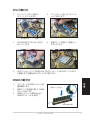
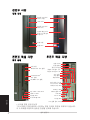
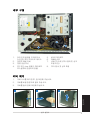
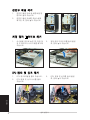
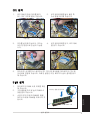
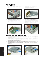
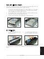
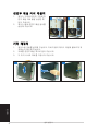
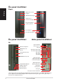
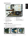
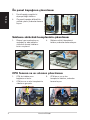
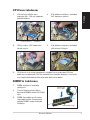
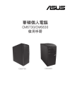
English
P1-P5945G/P2-P5945G
ASUS PC (Desktop Barebone)
Installation Manual
Download the latest manual from the ASUS website: www.asus.com
Front panel features
Close
English
Optical drive eject
button
HDD LED
Optical drive bay
cover
Press to open the
front panel cover
Power button
Power LED
Front panel features
Rear panel features
Open
Reset button
MS/MS Pro card slot
Power connector
Voltage selector*
Center/Sub out
Rear Surround L/R
Side ������������
Surround L/R
Line In
Line Out
Rear MIC
CompactFlash® card
slot
SD/MMC card slot
PS/2 mouse port
PS/2 keyboard port
LAN (RJ-45) port
USB 2.0 ports
4-pin IEEE 1394 port
USB 2.0 ports
Headphone port
SPDIF Out port
VGA port
DVI-D port
Microphone port
Serial port
PCI slot metal brackets
* The system’s power supply unit has a
115 V/230 V voltage selector switch located near the power connector. Use this switch
to select the correct system input voltage according to the voltage supply in your area.
Installation manual
English
Internal components
3
1
2
5
4
8
7
6
1.
2.
3.
4.
5.25-inch optical drive and
3.5 inch hard disk drive cage
Front panel cover
Power supply unit
PCI card riser bracket
(connected to the
motherboard PCI slot)
5.
6.
7.
8.
ASUS motherboard
DIMM sockets
LGA775 socket (under the CPU
fan and heatsink assembly)
CPU fan and heatsink assembly
Removing the cover
1.
Remove the cover screws. Keep the screws for later use.
2.
Pull the cover slightly toward the rear panel.
3.
Lift the cover, then set aside.
1
2
3
Installation manual
Removing the front panel cover
English
1.
Lift the front panel cover
hooks outward.
2.
Carefully remove the front
panel cover, then set it aside.
1
2
Removing the storage drive assembly
1.
Lay the system on its side,
then locate and remove three
storage drive assembly screws.
2.
Lift the storage drive assembly,
then set aside.
Removing the CPU fan and heatsink
1. Disconnect the CPU fan cable.
2.
Loosen the CPU fan and
heatsink assembly screws.
3.
Lift the CPU fan and heatsink
assembly, then set aside.
Installation manual
1.
Unlock the load lever, then lift
to a 90º-100º angle.
Retention tab
2.
Lift the load plate, then
remove the PnP cap.
4.
Close the load plate, then lock
the load lever.
English
Installing the CPU
Load lever
3.
Install the CPU. The CPU fits in
only one orientation.
5.
Reinstall the CPU fan and heatsink assembly, then reconnect the CPU
fan cable to the CPU fan connector on the motherboard. Refer to the
instructions in the previous section for details.
Installing a DIMM
1.
Locate the DIMM sockets in the
motherboard.
2.
Unlock a DIMM socket by
pressing the retaining clips
outward.
3.
Align a DIMM on the socket
such that the notch on the
DIMM matches the break on the
socket.
Installation manual
Unlocked
retaining clip
DDR DIMM notch
Installing an expansion card
Lift the PCI riser card assembly
to remove.
2.
Remove the metal cover
opposite the slot that you
intend to use.
3.
Insert the card connector to
the slot, then press the card
firmly until it fits in place.
Secure the card with a screw.
4.
Reinstall the PCI riser card
assembly. Make sure that the
riser card connector sits properly
on the motherboard PCI slot.
English
1.
Installing optical and storage drives
1.
2.
3.
Turn the storage drive assembly upside down with the 3.5-inch bay on
top of the 5.25-inch bay.
Insert the optical drive upside down to the 5.25-inch bay, then secure
it with two screws on both sides.
Turn the storage drive assembly, insert the hard disk drive upside down to
the 3.5-inch bay, then secure it with two screws on both sides.
2
3
Installation manual
Before reinstalling the storage drive assembly, connect the IDE/SATA and
power plugs to the IDE/SATA and power connectors at the back of the
drives.
1.
Connect the black plug of the IDE cable to the optical drive, then the
gray plug to the hard disk drive. If you have the SATA HDD, connect
the SATA cable to the SATA HD.
2.
Connect the 4-pin power plugs to the power connectors at the back
of the drives.
3.
Install the storage drive assembly to the chassis.
4.
Secure the storage drive assembly with three screws.
3
English
Reinstalling the storage drive assembly
4
Installing the foot stand
1.
Match the foot stand hooks to
the holes on the chassis.
2.
Pull the foot stand to the
direction of the arrow until the
lock clicks in place.
To remove the foot stand, lift the lock, then slightly push the foot stand to
the direction of the rear panel until it disengages from the chassis.
Installation manual
Reinstalling the front panel cover
English
1.
2.
Insert the front panel cover
tabs to the holes at the right
side of the chassis, then close.
Insert the front panel cover
hooks to the chassis tabs until
the front panel cover fits in
place.
1
2
Reinstalling the cover
1.
2.
3.
1
Install the cover to the chassis. Make sure the cover tabs fit the chassis rails.
Push the cover toward the front panel until it fits in place.
Secure the cover with two screws.
2
3
Installation manual
Manuel d’installation
Téléchargez les derniers manuels depuis le site web d’ASUS: www.asus.com.
Français
P1-P5945G/P2-P5945G
ASUS PC (Système barebone)
Caractéristiques de la façade
Fermé
Bouton d’ejection
du lecteur optique
LED HDD
Capot de la baie
du lecteur optique
Français
Appuyez pour
ouvrir le capot
de la façade
Bouton
d’alimentation
LED
d’alimentation
Caractéristiques de
la façade
Ouvert
Bouton Reset
Slot pour cartes
MS/MS Pro
Slot pour cartes
CompactFlash®
Slot pour cartes
SD/MMC
Port IEEE 1394
4 broches
Ports USB 2.0
Port Casque
Port Microphone
Caractéristiques de
l’arrière
Connecteur
d’alimentation
Sélecteur de tension*
Center/Sub out
Rear Surround L/R
Side Surround L/R
Port Line In
Port Line Out
MIC arrière
Port souris PS/2
Port clavier PS/2
Port LAN (RJ-45)
Ports USB 2.0
Port SPDIF Out
Port VGA
Port DVI-D
Port Série
Brackets métalliques des ports PCI
*L’alimentation du système est équipée d’un sélecteur de tension 115 V/230 V situé près du
connecteur d’alimentation. Utilisez cet interrupteur pour choisir la bonne tension d’entrée en
fonction des standards utilisés dans votre région.
Manuel d’installation
Composants internes
3
2
5
4
Français
1
8
7
6
1. Bloc du lecteur optique 5.25’’ et
du lecteur de disque dur 3.5’’.
5.
Carte mère ASUS
2.
Façade
6.
Sockets DIMM
3.
Alimentation
7.
Socket LGA775 (sous le
système de refroidissement du
CPU)
Système de refroidissement du
CPU
4. Bracket du PCI Card Riser
(connecté au slot PCI de la
carte mère)
8.
Enlever le capot
1.
Enlevez les deux vis. Conservez les vis pour un usage ultérieur.
2.
Tirez légèrement le panneau vers l’arrière.
3.
Soulevez le capot, puis basculez-le.
1
2
3
Manuel d’installation
Retirer le capot de la façade
1.
Levez les crochets du capot
avant vers l’extérieur.
2.
Retirez avec précaution le
capot, puis mettez-le de côté.
1
2
Français
Retirer l ’ensemble de stockage
1.
Posez le système sur le côté,
puis localisez et retirez les
trois vis de l’ensemble de
stockage.
2.
Soulevez l’ensemble de
stockage, puis mettez-le de
côté.
Retirez le dissipateur et le ventilateur du CPU
1. Déconnectez le câble de
ventilation du CPU.
2.
Retirez les vis de l’ensemble
dissipateur/ventilateur du CPU.
3.
Soulevez l’ensemble
dissipateur/ventilateur du CPU,
puis mettez-le de côté.
Manuel d’installation
Installer un CPU
Soulevez le levier dans la
direction de la flèche à un
angle de 90º-100º .
2.
Soulevez la plaque, puis retirez
le couvercle PnP.
4.
Refermez la plaque puis
verrouillez le levier.
Français
1.
Onglet de rétention
Levier
3.
Installez le CPU. Le CPU ne
peut être placé que dans un
seul sens.
5.
Réinstallez l’ensemble dissipateur/ventilateur du CPU, puis
reconnectez le câble du ventilateur CPU au connecteur de la carte
mère marqué CPU_FAN. Référez-vous aux instructions de la section
précédente pour plus de détails.
Installer un module DIMM
1.
Localisez les sockets DIMM de la
carte mère.
2.
Déverrouillez un socket DIMM en
pressant sur les clips de rétention
vers l’extérieur.
3.
Alignez un module DIMM sur le
socket de sorte que l’encoche sur
la DIMM corresponde à l’ergot du
socket.
Clip de rétention
déverrouillé
Encoche du DIMM DDR
Manuel d’installation
Installer une carte d’extension
Français
1.
Soulevez l’ensemble PCI Riser
Card pour le retirez du châssis.
2.
Retirez la protection
métallique faisant face au slot
que vous désirez utiliser.
3.
Insérez le connecteur de la
carte dans le slot et pressez
jusqu’à ce que la carte soit en
place. Sécurisez la carte avec
une vis.
4.
Réinstallez l’ensemble PCI Riser
Card. Assurez-vous que le
connecteur de la riser card soit
bien connecté au slot PCI de la
carte mère.
Installer un lecteur optique ou de stockage
1.
Placez l’ensemble de stockage de façon à ce que la baie 3.5” soit au
dessus de la baie 5.25”.
2.
Insérez le lecteur optique dans la baie 5.25”, puis sécurisez-le avec
deux vis de chaque côté.
3.
Insérez le disque dur dans la baie 3.5”, puis sécurisez-le avec deux vis
de chaque côté.
2
3
Manuel d’installation
Réinstaller l’ensemble de stockage
Avant de réinstaller l’ensemble de stockage, connectez les prises IDE /
SATA et d’alimentation aux connecteurs IDE / SATA et d’alimentation
situés à l’arrière des lecteurs.
Connectez la prise noire du câble IDE au lecteur optique, puis la prise
grise au disque dur. Si vous possédez un disque dur SATA, connectez
le câble SATA à ce disque dur.
2.
Connectez la prise d’alimentation 4 broches aux connecteurs
d’alimentation situés à l’arrière des lecteurs.
3.
Installez l’ensemble de stockage sur le châssis.
4.
Sécurisez l’ensemble de stockage avec trois vis.
3
Français
1.
4
Installer le pied de support
1.
Faites correspondre les
crochets du pied de support
aux ouvertures sur le châssis.
2.
Tirez le pied de support dans
la direction de la flèche jusqu’à
ce qu’il soit bien en place.
Pour retirer le pied de support, soulevez le verrou, puis poussez
délicatement le pied de support jusqu’à ce qu’il se désengage du châssis.
Manuel d’installation
Réinstaller le capot de la façade
Français
1.
Insérez les onglets du capot
dans les ouvertures situées
à droite du châssis, puis
refermez-le.
2.
Insérez les crochets du capot
de la façade dans les onglets
du châssis jusqu’à ce que le
capot soit bien en place.
2
Réinstaller le panneau
1.
Installer le panneau sur le châssis en vous assurant que les onglets du
panneau soient bien alignés sur les rails du châssis.
2.
Poussez le panneau vers l’avant jusqu’à ce qu’il soit bien en place.
3.
Sécurisez le panneau avec deux vis.
1
1
2
3
Manuel d’installation
P1-P5945G/P2-P5945G
安裝手冊
請至華碩網站下載最新的產品使用手冊 www.asus.com
繁體中文
華碩個人電腦(桌上型準系統)
前面板功能
外觀功能
光碟機退出鈕
硬碟指示燈
光碟機插槽
輕壓一下打開
I/O 外蓋
電源按鈕
電源指示燈
繁體中文
前面板功能
後面板功能
內部連接埠
電源插�
頭
電壓選擇開關
中置/重低音環繞喇叭接頭
後置環繞喇叭接頭
側邊環繞喇叭接頭
Reset 按鈕
MS/MS Pro 記憶
卡插槽
音效輸入
音效輸出
麥克風
CompactFlash 記憶
卡插槽
SD/MMC card 記憶
卡插槽
PS/2 滑鼠
PS/2 鍵盤
RJ-45 網路埠
���
USB 2.0 埠
�
4-pin IEEE 1394 埠
�
SPDIF 輸出埠
���
VGA 埠
�
DVI-D 埠
�
USB 2.0 埠
耳機
麥克風
串列埠
PCI 插槽
��
* 電源供應器插座旁有一個電壓選擇開關,你可以利用這個開關切換到適合您所在區域所使用的電壓值。
若您所在區域提供電壓為 100-127V,請切換到 115V;若您所在區域提供電壓為 200-240V,請切換到
230V。
安裝手冊
內部組件
3
1
2
5
4
8
1.
5.25 吋裝置插槽及3.5 吋硬碟機模
組支架
2.
前面板
3.
電源供應器
4.
PCI 轉接卡模組(安插在主機板的
PCI 插槽)
5.
6.
7.
8.
繁體中文
7
6
主機板
DIMM 插槽
LGA775 CPU 插座 (位於風扇的
下方)
CPU 風扇
打開機殼
1.
鬆開機身後方的二顆機殼固定螺絲,並暫置於一旁。
2.
將機殼小心地從機身後方推出。
3.
取出機殼並暫置於一旁。
1
2
3
安裝手冊
移除前面板
1.
將前面板左側的三個固定卡榫往外
扳開。
1
2
移除儲存裝置模組
1.
將主機平躺在桌面上,移除儲存裝
置支架的三顆固定螺絲。
取出儲存裝置支架並暫置於一旁。
3.
取出 CPU 風扇並暫置於一旁。
繁體中文
2.
移除 CPU 風扇
1. 移除 CPU 風扇電源線。
2.
鬆開 C P U 風扇的四顆固定螺
絲,。
安裝手冊
安裝 CPU
將固定扳手扳開至��������
����������������
90-100��
度。
固定扣
2.
將
�����������������
CPU 安裝盒的上蓋掀起,並移
除 CPU 安裝盒上的保護蓋。
4.
將上蓋重新蓋上,接著請將固定扳
���������������
手朝原方向推回,並扣於固定扣之
上。
回定扳手
3.
安裝
�������
CPU 至插槽上。注意 CPU 只
�������� ���� �
能以單一方向正確地安裝到主機板
上的插槽。
5.
裝回
�����������������������������
CPU 風扇並接回風扇電源線。請參考前面小節的說明。
繁體中文
1.
安裝記憶體模組
1.
請先找到主機板上的記憶體模組插
槽。
2.
將記憶體模組插槽兩端的白色固定
卡榫扳開。
3.
將記憶體模組的金手指對齊記憶體
模組插槽的溝槽,將記憶體模組插
入插槽中,若無錯誤,插槽兩端的
白色卡榫會因記憶體模組置入而自
動扣到記憶體模組兩側的凹孔中。
安裝手冊
扳開二端的白
色卡榫
DDR DIMM 凹槽
��
安裝擴充卡
1.
將 PCI 轉接卡模組取出。
2.
移除您欲安裝插槽所對應的金屬擋
板。
3.
將擴充卡安裝在子卡插槽上,並鎖
上一顆固定螺絲。
4.
將 PCI 轉接卡模組裝回主機內,
注意是否正確安插在主機板的 PCI
插槽上。
繁體中文
安裝光碟機及硬碟機
1.
2.
將儲存裝置模組反轉過來,使硬碟插槽在上方,光碟機插槽在下方。
將光碟機反向裝入光碟機插槽中,並在二側各鎖上二顆固定螺絲。
3.
接著再將硬碟機反向裝入硬碟插槽中,同樣在二側各鎖上二顆固定螺絲。注意
硬碟後端接頭需與光碟機後端接頭位在同一側。
3
2
安裝手冊
裝回儲存裝置模組
裝回儲存裝置模組之前,請���
先將� ���������
IDE/SATA �����������������
排線及電源線�����������
連接至裝置後端的接頭�
。
1.
請將 I D E 排線的黑色接頭連接至光碟機,灰色接頭連接硬碟機。�����
若您使用 SATA 硬碟,請連接 SATA 排線至 SATA 硬碟。
2.
連接 4-pin 電源接頭至裝置後方的電源接頭。
3.
裝回儲存裝置模組。
4.
鎖上三顆固定螺絲。
3
繁體中文
4
安裝腳座
1.
取出腳座並將腳座的卡榫對準機殼
底部的孔。
2.
順著箭頭方向輕推,使腳座正確固
定在機殼底部。
若要移除腳座,請將腳座往機殼後方推出,鬆開卡榫後即可取下。
安裝手冊
裝回前面板
1.
2.
將前面板����������
右側卡榫對準機身的卡
溝小心地裝入,然後輕輕地闔
上。
確認另一側的卡榫已確實固定在
��������������
主機上
1
2
裝回機殼
1.
2.
3.
繁體中文
1
將機殼裝回,注意機殼前方的卡榫必須對準機身前方的卡溝。
���������������������������
將機殼從機身後方往前方推入,並確實固定在機身上。
鎖上二顆固定螺絲。
���������
2
3
安裝手冊
P1-P5945G/P2-P5945G
華碩個人電腦(桌上型準系統)
簡體中文
安裝手冊
請至華碩網站下載最新的產品用戶手冊 www.asus.com
前面板功能
外觀功能
光����
驅���
退出鈕
硬����
盤���
指示燈
光���
驅��
插槽
輕壓一下打
開 I/O 外蓋
電源按鈕
電源指示燈
前面板功能
後面板功能
內部連接接口
簡體中文
電源插頭
電壓選擇開關
中置/重低音環繞喇叭
Reset 按鈕
MS/MS Pro 存
�
儲卡��
插槽
後置環繞喇叭接頭
側邊環繞喇叭接頭
音頻��
輸入
音頻��
輸出
麥克風
CompactFlash
存儲卡��
插槽
SD/MMC card
存儲卡��
插槽
PS/2 鼠標
��
PS/2 鍵盤
RJ-45 網���
絡接口
USB 2.0 接口
��
4-pin IEEE 1394 接口
��
USB 2.0 接口
��
耳機
麥克風
SPDIF 輸出接口
����
VGA 接口
��
DVI-D 接口
��
串口
PCI 插槽
* 電源供應器插座旁有一個電壓選擇開關,你可以利用這個開關切換到適合您所在區域所使用
的電壓值。若您所在區域提供電壓為 100-127V,請切換到 115V;若您所在區域提供電壓為
200-240V,請切換到 230V。
安裝手冊
內部組件
3
1
2
5
4
8
7
6
5.25 吋設備插槽及3.5 吋硬盤模塊
支架
2.
前面板
3.
電源供應器
4.
P C I 轉接卡模塊(安插在主板的
PCI 插槽)
5.
6.
7.
8.
主板
DIMM 插槽
LGA775 CPU 插座 (位於風扇的
下方)
CPU 風扇
簡體中文
1.
打開��
機箱
1.
鬆開機身後方的二顆��������������
機箱������������
固定螺絲,並暫置於一旁。
2.
將�������������
機箱�����������
小心地從機身後方推出。
3.
取出���������
機箱�������
並暫置於一旁。
1
2
3
安裝手冊
去����
除前面板
1.
將前面板左側的三個固定卡榫往外
扳開。
1
2
去除存儲設備模塊
1.
將主機平躺在桌面上,去除存儲設
備支架的三顆固定螺絲。
簡體中文
2.
取出存儲設備支架並暫置於一旁。
3.
取出 CPU 風扇並暫置於一旁。
去除 CPU 風扇
1. 去除 CPU 風扇電源線。
2.
鬆 開 C P U 風 扇 的 四 顆 固定螺
絲,。
安裝手冊
安裝 CPU
1.����������������
將固定扳手扳開至��������
90-100��
度。
回定扳手
3.���������������
安裝 CPU 至插槽上。注意 CPU
����
只能以單一方向正確地安裝到主板
上的插槽。
4.���������������
將上蓋重新蓋上,接著請將固定扳
手朝原方向推回,並扣於固定扣之
上。
簡體中文
固定扣
2.�����������������
將 CPU 安裝盒的上蓋掀起,並移
除 CPU 安裝盒上的保護蓋。
5.�����������������������������
裝回 CPU 風扇並接回風扇電源線。請參考前面小節的說明。
安裝���
內存條
扳開二端的白
色卡榫
1.
請先找到主板上的內存條插槽。
2.
將內存條插槽兩端的白色固定卡
榫扳開。
3.
將內存條的金手指對齊內存條插
槽的溝槽,將內存條插入插槽
中,若無錯誤,插槽兩端的白色
卡榫會因內存條置入而自動扣到
內存條兩側的凹孔中。
安裝手冊
DDR DIMM 凹槽
安裝���
擴展�
卡
1.
將 PCI 轉接卡�����
模塊���
取出。
2.���������������
去��������������
除您欲安裝插槽所對應的金屬擋
板。
3.
將��������������
擴展������������
卡安裝在子卡插槽上,並鎖
上一顆固定螺絲。
4.
將 PCI 轉接卡��������
模塊������
裝回主機內,
注意是否正確安插在��������
主板������
的 PCI
插槽上。
簡體中文
安裝�����
光驅���
及��
硬盤
1.
2.
將����������������������������
存儲設備模塊����������������������
反轉過來,使����������������
硬盤��������������
插槽在上方,��������
光驅������
插槽在下方。
將��������������������������
光驅������������������������
反向裝入��������������������
光驅������������������
插槽中,並在二側各鎖上二顆固定螺絲。
3.
接著再將������������������������������
硬盤����������������������������
反向裝入������������������������
硬盤����������������������
插槽中,同樣在二側各鎖上二顆固定螺絲。注意�
硬
盤������������������
後端接頭需與������������
光驅����������
後端接頭位在同一側。
3
2
安裝手冊
裝回������
存儲設備模塊
裝回�������������
存儲設備模塊�������
之前,請先��
將� ���������
IDE/SATA �����������������
排線及電源線�����������
連接至設備后端的接頭�
。
1.
請將 IDE 排線的黑色接頭連接至�����������������
光驅���������������
,灰色接頭連接��������
硬盤������
。�����
若您使用 �����
SATA
硬盤,請連接 SATA 排線至硬盤。
2.
連接 4-pin 電源接頭至����������
設備��������
後方的電源接頭。
3.
裝回�������
存儲設備模塊�
。
4.鎖上三顆固定螺絲。
3
4
安裝腳座
取出腳座並將腳座的卡榫對準��
機箱
底部的孔。
2.
順著箭頭方向輕推,使腳座正確固
定在�����
機箱���
底部。
簡體中文
1.
若要移除腳座,請將腳座往�����������������
機箱���������������
後方推出,鬆開卡榫後即可取下。
安裝手冊
裝回前面板
1.
將前面板����������
右側卡榫對準機身的卡
溝小心地裝入,然後輕輕地闔
上。
2.��������������
確認另一側的卡榫已確實固定在
主機上
1
2
裝回��
機箱
1.���������������������������
將機箱裝回,注意機箱前方的卡榫必須對準機身前方的卡溝。
2. 將機箱從機身後方往前方推入,並確實固定在機身上。
3. 鎖上二顆固定螺絲。
���������
1
2
3
簡體中文
安裝手冊
P1-P5945G/P2-P5945G
ASUS PC (デスクトップ ベアボーン)
日本語
インストールマニュアル
最新のマニュアルをASUSのWebサイトからダウンロードしてください:www.asus.com.
フロントパネル
閉じた状態
光学ドライブ
イジェクトボタン
HDD LED
光学ドライブベイ
カバー
押すとフロントパネル
カバーが開く
電源ボタン
電源 LED
フロントパネル
リアパネル
開けた状態
電源コネクタ
電圧セレクタ*
リセットボタン
センター/サブ出力
MS/MS Pro カード
���
スロット
リアサラウンド L/R
サイドサラウンド L/R
ライン入力
ライン出力
リアマイク
CompactFlash® カード
���
スロット
日本語
SD/MMC カード
���
スロット
4ピン IEEE 1394 ポート
USB 2.0 ポート
ヘッドフォンポート
マイクポート
PS/2 マウスポート
PS/2 キーボードポート
LAN (RF-45) ポート
USB 2.0 ポート
SPDIF 出力ポート
VGA ポート
DVI-D ポート
シリアルポート
PCI スロット金属ブラケット
* システムの電源には、電源コネクタの側に 115 V/230 V 電圧セレクタスイッチがあります。このスイッチを使っ
て、ご利用地域の電圧に合わせて適切なシステム入力電圧を選択します。
インストールマニュアル
内部コンポーネント
3
1
2
5
4
8
7
6
1.
5.25インチ 光学ドライブと
3.5インチHDDケージ
5.
ASUS マザーボード
2.
フロントパネルカバー
6.
DIMM ソケット
3.
光学ドライブロック
7.
4.
PCI カードライザーブラケット(マ
ザーボードのPCIスロットに接続)
LGA775ソケット (CPU ファンおよび
放熱板の下)
CPU 用ファンおよび放熱板
8.
カバーの取外し
カバー用ネジを取り外します。ネジは後で使用しますので、紛失しないで下さい。
2.
カバーをリアパネルの方向に引きます。
3.
カバーを持ち上げて脇に置いておきます。
1
2
日本語
1.
3
インストールマニュアル
フロントパネルカバーを取り外す
1.
フロントパネルカバーのフックを外
します。
2.
フロントパネルカバーを外します。
1
2
記憶ドライブを取り外す
1.
システムを図のように置き、記憶ド
ライブを固定している3つのネジ
を外します。
2.
記憶ドライブを取り外します。
CPUファンとヒートシンクを取り外す
日本語
1. CPU 用ファンケーブルを外します。
2.
CPUファンとヒートシンクを固定し
ているネジをゆるめます。
3.
CPUファンとヒートシンクを持ち上
げ、外します。
インストールマニュアル
CPU の取付け
1.
ロードレバーのロックを外し、
90°
〜100°
上げます。
受け側のツメ
2.
ロードプレートを上げ、ソケットキ
ャップを外します。
4.
装着プレートを閉じて、装着レバー
をロックします。
装着レバー
3.
CPU をはめます。CPU は一方向の
みフィットします。
5.
CPUファンとヒートシンクを取り付け、CPUファンケーブルをCPUファンコネクタ
に接続します。詳細は前のセクションをご覧ください。
1.
マザーボードの DIMM ソケットの位
置を確認します。
2.
固定クリップを外側に押して、DIMM
ソケットを外します。
3.
DIMM とソケットの溝を合わせて
DIMM をソケットにはめます。
日本語
DIMM の取付け
固定クリップを外す
DDR DIMM の溝
インストールマニュアル
拡張カードの取付け
1.
PCI ライザーカードを上に引き、取
り外します。
3. カードコネクタをスロットには
めて、カードが止まるまでしっ
かり押しこみます。カードをネ
ジで固定します。
2.
使用するスロットに対応する金属
製カバーを外します。
4.
PCI ライザーカードを再び取り付
け、ライザーカードコネクタがPCI
スロットにしっかりはまっているこ
とを確認します。
光学ドライブと記憶ドライブを取り付ける
日本語
1.
図のように記憶ドライブを、3.5インチベイが5.25インチベイの上になるように置
きます。
2.
光学ドライブを上下逆さまの状態で5.25インチベイに入れ、2つのネジで固定し
ます。
3.
HDDを上下逆さまの状態で3.5インチベイに入れ、2つのネジで固定します。
2
3
インストールマニュアル
記憶ドライブを再び取り付ける
作業の前に、IDE / SATA と電源プラグを各コネクタに接続します。
1.
IDE ケーブルの黒いプラグを光学ドライブに、グレーのプラグをHDDに接続しま
す。���������������������������������������
SATA HDDがある場合は、SATA ケーブルをSATA HDに接続します。
2.
4ピン電源プラグを電源コネクタに接続します。
3.
記憶ドライブをケースに取り付けます。
4.
記憶ドライブをネジで3ケ所固定します。
3
4
フットスタンドを取り付ける
フットスタンドのフックをケースの
穴に合わせます。
2.
フットスタンドをロックされるまで
矢印の方向に動かします。
日本語
1.
フットスタンドを外す場合は、ロックを上げ、ケースから外れるまでフットスタンドをリ
アパネルの方向に動かします。
インストールマニュアル
フロントパネルカバーを再びインストールする
1.
フロントパネルカバーのタブをケ
ースの右サイドの穴に入れ、閉じま
す。
2.
フロントパネルカバーのフックを
ケースのタブにしっかり固定しま
す。
1
2
カバーを再び取り付ける
1.
カバーをケースに取り付けます。カバーのタブをシャーシのレールにしっかり合
わせます。
2.
カバーをフロントパネルの方向にスライドさせます。
3.
2つのネジでカバーを固定します。
1
2
3
日本語
インストールマニュアル
P1-P5945G/P2-P5945G
ASUS PC (데스크탑 베어본)
한국어
빠른 설치 가이드
최신 사용자 설명서 다운로드: www.asus.com
전면부 사양
닫힌 상태
옵티컬 드라이브
꺼내기 버튼
HDD LED
옵티컬 드라이브
베이 커버
전면부 패널 커버
를 열기 위해 눌러
주십시오.
전원 버튼
전원 LED
후면부 패널 사양
전면부 패널 사양
열린 상태
전원 커넥터
전압 셀렉터*
중앙/서브 출력
리셋 버튼
MS/MS Pro 카드 슬롯
후면부 서라운드 L/R
측면부 서라운드 L/R
CompactFlash®
카드 슬롯
라인 입력
라인 출력
후면부 MIC
SD/MMC 카드 슬롯
PS/2 마우스 포트
PS/2 키보드 포트
LAN (RJ-45) 포트
USB 2.0 포트
4핀 IEEE 1394 포트
USB 2.0 포트
헤드폰 포트
마이크로폰 포트
SPDIF 출력 포트
VGA 포트
DVI-D 포트
시리얼 포트
한국어
PCI 슬롯 금속 브래킷
* 시스템 전원 공급 유닛의
115 V/230 V 전압 셀렉터 스위치는 전원 커넥터 주변에 위치하고 있습니다.
이 스위치를 이용하여 알맞은 전압을 선택해 주십시오.
설치 설명서
내부 구성
3
1
2
5
4
8
7
6
1.
2.
3.
4.
5.25 인치 옵티컬 드라이브 &
3.5 인치 하드 드라이브 케이스
전면부 패널 커버
전원 공급 유닛
PCI 카드 riser 브래킷 (마더보드
PCI 슬롯에 연결되어 있음)
5.
6.
7.
8.
ASUS 마더보드
DIMM 소켓
LGA775 소켓 (CPU 팬과 힛 싱크
조립 하단)
CPU 팬 & 힛 싱크 조립
커버 제거
1.
커버 나사를 제거한 후, 잘 보관해 주십시오.
2.
커버를 바깥 방향으로 밀어 주십시오.
3.
커버를 들어 옆에 보관해 주십시오.
2
3
한국어
1
설치 설명서
전면부 패널 제거
1.
전면부 패널 커버 걸쇠를 바깥 방
향으로 올려 주십시오.
2.
전면부 패널 커버를 조심스럽게
제거한 후, 옆에 놓아 주십시오.
1
2
저장 장치 드라이브 제거
1.
시스템을 옆으로 눕힌 후, 저장 장
치 드라이브의 나사 3개를 제거해
주십시오.
2.
저장 장치 드라이브를 들어 올린
후, 옆에 놓아 주십시오.
3.
CPU 팬과 힛 싱크를 들어 올린
후, 옆에 놓아 주십시오.
CPU 팬과 힛 싱크 제거
1. CPU 팬 케이블을 뽑아 주십시오.
2.
CPU 팬과 힛 싱크 나사를 풀어
주십시오.
한국어
설치 설명서
CPU 설치
1.
로드 레버의 잠금 장치를 풀고,
90°-100° 각도로 올려 주십시오.
리텐션 탭
2.
로드 플레이트를 들어 올린 후,
PnP 캡을 제거해 주십시오.
4.
로드 플레이트를 닫고, 로드 레버
를 잠가 주십시오.
로드 레버
3.
CPU를 설치해 주십시오. CPU는
오직 한 방향으로만 설치 가능합
니다.
5.
CPU와 힛 싱크를 다시 설치하신 후, CPU 팬 케이블을 마더보드의 CPU 팬
커넥터에 연결해 주십시오. 자세한 설명은 이전 페이지의 설치 절차를 참고
해 주십시오.
DIMM 설치
마더보드의 DIMM 소켓 위치를 확인
해 주십시오.
2.
고정 클립을 밖으로 눌러 DIMM 소
켓을 열어 주십시오.
3.
소켓의 분리 지점과 DIMM의 홈을
맞추어 소켓에 DIMM을 위치시켜 주
십시오.
리테이닝 클립 잠금 해지
한국어
1.
DDR DIMM 노치
설치 설명서
확장 카드 설치
1.
PCI 라이저 카드를 제거해 주십시
오.
2.
사용하려는 슬롯 반대쪽의 금속
커버를 제거해 주십시오.
3.
슬롯에 카드 커넥터를 장착한 후,
나사로 완전히 고정시켜 주십시
오.
4.
PCI 라이저 카드를 재설치 해 주
십시오. 라이저 카드 커넥터 부분
이 마더보드 PCI 슬롯에 올바르게
위치했는지 확인해 주십시오.
옵티컬 & 저장 장치 드라이브 설치
1.
2.
3.
5.25 인치 베이 위에 3.5 인치 베이가 위치하도록 저장 장치 드라이브를 거꾸
로 돌려 주십시오.
거꾸로 위치한 5.25 인치 베이에 옵티컬 드라이브를 삽입한 후, 두 개의 나사
로 양쪽 면을 고정시켜 주십시오.
저장 장치 드라이브를 돌린 후, 3.5 인치 베이에 하드 디스크 드라이브를 거
꾸로 넣어 주십시오. 드라이브 삽입 후, 두 개의 나사로 양쪽 면을 고정시켜
주십시오.
3
2
한국어
설치 설명서
저장 장치 드라이브 재설치
저장 장치 드라이브를 재설치 하기 전에, IDE/SATA 및 전원 플러그를 드라이브 후
면부에 위치한 IDE/SATA & 전원 커넥터에 연결해 주십시오.
1.
IDE 케이블의 검은색 플러그를 옵티컬 드라이브에 연결해 주시고, 회색 플러
그는 하드 디스크 드라이브에 연결해 주십시오. 만약 SATA HDD가 있다면,
SATA 케이블을 SATA HDD에 연결해 주십시오.
2.
4핀 전원 플러그를 드라이브 후면에 위치한 전원 커넥터에 연결해 주십시오.
3.
케이스에 저장 장치 드라이브를 설치해 주십시오.
4.
세 개의 나사로 저장 장치 드라이브를 완전히 고정시켜 주십시오.
3
4
풋 스탠드 설치
1.
풋 스탠드의 걸쇠를 케이스 구멍
에 맞춰 주십시오.
2.
풋 스탠드를 화살표 방향으로 딸
각 소리가 날 때까지 당겨 주십시
오.
한국어
풋 스탠드를 제거하기 위해서는 잠금 장치를 푼 후, 후면부 패널 방향으로 밀어 주
십시오.
설치 설명서
전면부 패널 커버 재설치
1.
2.
케이스 우측에 위치한 구멍에 전
면부 패널 커버 탭을 삽입한 후,
닫아 주십시오.
케이스 탭에 전면부 패널 걸쇠를
삽입해 주십시오.
1
2
커버 재설치
1.
2.
3.
1
케이스에 커버를 설치해 주십시오. 커버의 탭이 케이스 레일에 올바르게 위
치했는지 확인해 주십시오.
커버를 전면부 패널 쪽으로 밀어 주십시오.
두 개의 나사로 커버를 고정시켜 주십시오.
2
3
한국어
설치 설명서
Türkçe
P1-P5945G/P2-P5945G
ASUS PC (Mini Masaüstü Bilgisayar)
Kurulum Elkitabı
ASUS web sitesinden en yeni kullan›m elkitab›n› indirin: www.asus.com.
Ön panel özellikleri
Kapat
Türkçe
Optik sürücü açma
dü¤mesi
HDD LED Göstergesi
Optik sürücü
yuvas›n›n kapa¤›
Ön panel kapa¤›n›
açmak için bas›n
Güç Dü¤mesi
Güç LED Göstergesi
Ön panel özellikleri
Arka panel özellikleri
Aç
S›f›rlama dü¤mesi
MS/MS Pro kart
yuvas›
Güç konektörü
Voltaj seçicisi*
Orta/alt
Arka Surround Sl/Sğ
Yan Surround Sl/Sğ
Hat Girifli
Hat Ç›k›fl›
Arka MİK
CompactFlash® kart
yuvas›
SD/MMC kart yuvas›
PS/2 fare girifli
PS/2 klavye girifli
LAN (RJ-45) girifli
4-pimli IEEE 1394 portu
USB 2.0 giriflleri
Kulakl›k girifli
Mikrofon girifli
USB 2.0 giriflleri
SPDIF Ç›k›fl portu
VGA girifli
DVI-D portu
Seri girifl
PCI yuvasu metal destekleri
* Sistem güç besleme ünitesinde güç konektörünün yan›na yerlefltirilen 115 V/230 V de¤erinde voltaj
seçme dü¤mesi bulunmaktad›r. Bölgenizdeki voltaj beslemesine göre uygun sistem girifl voltaj›n›
seçmek için bu dü¤meyi kullan›n.
Kurulum Elkitabı
Türkçe
Dahili bileflenler
3
1
2
5
4
8
7
6
1.
5.25 inç optic sürücü ve 3.5 inç
sabit disk sürücü kafesi
5.
ASUS anakart
2.
Ön panel kapa¤›
6.
DIMM soketleri
3.
Güç beslemesi ünitesi
7.
4.
PCI kart› kald›rma deste¤i
(anakart PCI yuvas›na
ba¤lanm›flt›r)
LGA775 soketi (CPU fan› ve ›s›
alma komplesi alt›nda)
CPU fan› ve ›s› alma komplesi
8.
Kapa¤›n ç›kar›lmas›
1.
Kapak vidalar›n› sökün. Vidalar› ileride kullanmak için saklay›n.
2.
Kapa¤› arka panele do¤ru yavaflça çekin.
3.
Kapa¤› kald›r›n, ard›ndan kenara koyun.
1
2
3
Kurulum Elkitabı
Ön panel kapa¤›n›n ç›kar›lmas›
Türkçe
1.
Panel kapa¤› çengellerini
d›flar›ya do¤ru kald›r›n.
2.
Ön panel kapa¤›n› dikkatli bir
flekilde ç›kar›n, ard›ndan kenara
koyun.
1
2
Saklama sürücüsü komplesinin ç›kar›lmas›
1.
Sistemi yan taraf›na koyun,
ard›ndan üç adet saklama
sürücüsü montaj vidalar›n›
bulun ve ç›kar›n.
2.
Saklama sürücü komplesini
kald›r›n, ard›ndan kenara koyun.
CPU fan›n›n ve ›s› al›c›n›n ç›kar›lmas›
1. CPU fan kablosunun
ba¤lant›s›n› kesin.
2.
3.
CPU fan› ve ›s› al›c› komplesinin
vidalar›n› gevfletin.
CPU fan›n› ve ›s› al›c›
komplesini kald›r›n, ard›ndan
kenara koyun.
Kurulum Elkitabı
1.
Yük kolunun kilidini aç›n,
ard›ndan 900 - 1000 aç› yapacak
flekilde kald›r›n.
Tutma sekmesi
2.
Yük plakas›n› kald›r›n, ard›ndan
PnP flapkas›n› ç›kar›n.
4.
Yük plakas›n› kapat›n, ard›ndan
yük kolunu kilitleyin.
Türkçe
CPU’nun tak›lmas›
Yük kolu
3.
CPU’yu tak›n. CPU sadece bir
yönde oturur.
5.
CPU fan›n› ve ›s› alma komplesini yeniden kurun, ard›ndan CPU fan
kablosunu anakarttaki CPU fan konektörüne yeniden ba¤lay›n. Ayr›nt›lar
için önceki bölümde verilen talimatlar bölümüne bak›n.
DIMM’in tak›lmas›
1.
DIMM soketlerini anakarta
yerlefltirin.
2.
Tutucu klipsleri d›flar› do¤ru
bast›rarak DIMM soketinin kilidini
aç›n.
3.
DIMM üzerindeki çentik soket
üzerindeki aç›kl›k ile eflleflecek
flekilde DIMM’i soket üzerinde
hizalay›n.
Kilidi aç›lan
tutucu klips
DDR DIMM çenti¤i
Kurulum Elkitabı
Geniflletme kart›n›n tak›lmas›
Ç›karmak için PCI kald›rma kart›
komplesini kald›r›n.
2.
Yuvan›n karfl›s›nda bulunan metal
kapa¤› ç›kar›n, böylece amaçland›¤›
gibi kullanabilmelisiniz.
3.
Kart konektörünü yuvaya tak›n,
ard›ndan yerine oturuncaya
kadar karta düzgün bir
flekilde bast›r›n. Kart› vidalar›
kullanarak sabitleyin.
4.
PCI kald›rma kart› komplesini
yeniden kurun. Kald›rma kart›
konektörünün anakart PCI
yuvas›na düzgün bir flekilde
oturdu¤undan emin olun.
Türkçe
1.
Optik ve saklama sürücülerinin kurulmas›
1.
2.
3.
Saklama sürücüsü komplesinin 3.5 inçlik yuvay› kullanarak 5.25 inçlik
yuvan›n üstünde üstünü alt›na getirin.
5.25 inçlik yuvay› optik sürücünün üstünü alt›na getirerek yerlefltirin,
ard›ndan her iki tarafta da iki vida kullanarak sabitleyin.
Saklama sürücü komplesini çevirin, sabit disk sürücüsünün üst k›sm›
alt tarafa gelecek flekilde 3.5 inçlik yuvaya yerlefltirin, ard›ndan her iki
tarafta da iki vida kullanarak sabitleyin.
3
2
Kurulum Elkitabı
Saklama sürücüsü komplesinin yeniden
kurulmas›
1.
IDE kablosunun siyah renkteki fiflini optik sürücüye ba¤lay›n, ard›ndan
gri renkteki fifli ise sabit disk sürücüsüne ba¤lay›n. SATA HDD'iniz varsa,
SATA kablosunu SATA HD'ye ba¤lay›n.
2.
4 pimli güç fifllerini sürücülerin arkas›nda bulunan güç konektörlerine
ba¤lay›n.
3.
Saklama sürücü komplesini flaseye tak›n.
4.
Saklama sürücü komplesini üç viday› kullanarak sabitleyin.
3
Türkçe
Saklama sürücü komplesini yeniden kurmadan önce, IDE / SATA ve güç
tapalar›n› IDE / SATA’ye ve güç konektörlerini sürücülerin arkas›na ba¤lay›n.
4
Ayak stand›n›n kurulmas›
1.
Ayak stand› çengellerini
flasedeki delikler ile efllefltirin.
2.
Kilit yerine t›k sesi ç›kararak
oturuncaya kadar ayak stand›n›
ok yönünde itin.
Ayak stand›n› ç›karmak için kilidi kald›r›n, ard›ndan ayak stand›n› flaseden
kurtuluncaya kadar yavaflça arka panele do¤ru itin.
Kurulum Elkitabı
Ön panel kapa¤›n›n yeniden tak›lmas›
Türkçe
1.
Ön panel kapa¤› sekmelerini
flasenin sa¤ taraf›ndaki
deliklere yerlefltirin, ard›ndan
kapa¤› kapat›n.
2.
Ön panel kapa¤› çengellerini ön
panel kapa¤› yerine oturuncaya
kadar flase sekmelerine tak›n.
1
2
Kapa¤›n yeniden tak›lmas›
1.
Kapa¤› flaseye tak›n. Kapak sekmelerinin flase raylar›na oturdu¤undan
emin olun.
2.
Kapa¤› yerine oturuncaya kadar ön panele do¤ru itin.
3.
Kapa¤› vidalar› kullanarak sabitleyin.
1
2
3
Kurulum Elkitabı