1
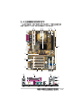
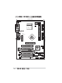
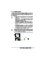
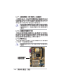
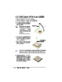
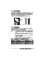
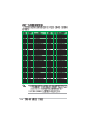
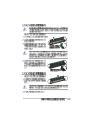
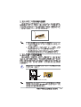
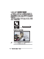
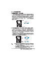
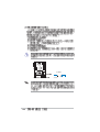
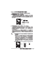
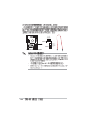
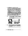
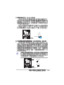
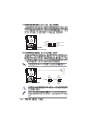
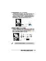
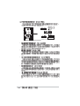
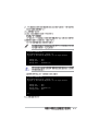
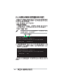
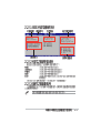
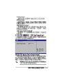
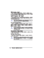
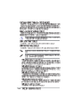
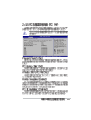
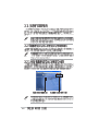
Motherboard
P4P800S
T1398
© 2003
2
3
4
•
•
•
•
•
•
•
•
•
•
•
•
5
•
•
•
6
™
1 2
Jumper Mode
2 3
Jumper Free
(Default)
P4P800S-TAYZ
6
10839 11036
0
99XX99XX99
7
8
®
®
®
®
®
®
9
10
1-1
®
®
®
®
1-2
®
1-3
•
•
•
•
1-4
1 2
3 4
5
6
7
8
17
16
15
14
13
18
12
11 10 9
19
20
21
22
23
28
27
26
25
24
1-5
®
®
1-6
1-7
20.8cm( 8.2in)
KBPWR1
Socket 478
CPU_FAN1
COM1
USBPW12
USBPW34
30.5cm (12.0in)
ATX12V1
P4P800S
SATA2
SATA1
®
FP_AUDIO1
CLRTC1
USBPW78
USBPW56
CD1
USB56
WIFI
1-8
CHA_FAN1
AUX1
MODEM1
USB78
CHASSIS1
SB_PWR1
GAME1
PANEL1
P4P800S
SB_PWR1
®
P4P800S Onboard LED
ON
Standby
Power
OFF
Powered
Off
1-9
1-10
®
®
®
®
®
®
®
1-11
®
®
90 - 100
®
®
®
®
1-12
80 Pins
104 Pins
®
DIMM2
DIMM1
P4P800S
P4P800S 184-Pin DDR DIMM Sockets
1-13
1-14
1-15
A
1-16
B
C
D
E
F
G
H
P4P800S
®
Keyed for 1.5v
P4P800S Accelerated Graphics Port (AGP)
1-17
P4P800S
WIFI
®
P4P800S Wi-Fi Slot
1-18
KBPWR1
1 2
2 3
+5V
(Default)
+5VSB
P4P800S
®
P4P800S Keyboard Power Setting
USBPW12
USBPW34
2 3
1 2
+5V
(Default)
+5VSB
USBPW78
USBPW56
P4P800S
®
1 2
P4P800S USB Device Wake Up
+5V
(Default)
2 3
+5VSB
1-19
P4P800S
CLRTC1
®
1 2
P4P800S Clear RTC RAM
1-20
Normal
(Default)
2 3
Clear CMOS
FLOPPY1
PIN 1
P4P800S
®
P4P800S Floppy Disk Drive Connector
ATXPWR1
Pin 1
P4P800S
®
+12.0VDC
+5VSB
PWR_OK
COM
+5.0VDC
COM
+5.0VDC
COM
+3.3VDC
+3.3VDC
+5.0VDC
+5.0VDC
-5.0VDC
COM
COM
COM
PS_ON#
COM
-12.0VDC
+3.3VDC
ATX12V1
+12V DC GND
+12V DC GND
P4P800S ATX Power Connectors
1-21
GND
RSATA_TXP2
RSATA_TXN2
GND
RSATA_RXN2
RSATA_RXP2
GND
SATA2
P4P800S
®
SATA1
P4P800S SATA Connectors
•
•
•
1-22
GND
RSATA_TXP1
RSATA_TXN1
GND
RSATA_RXN1
RSATA_RXP1
GND
1-23
SEC_IDE1
P4P800S
®
PRI_IDE1
PIN 1
P4P800S IDE Connectors
1-24
PIN 1
Chassis Signal
GND
+5VSB_MB
P4P800S
®
CHASSIS1
(Default)
P4P800S Chassis Alarm Lead
CPU_FAN1
GND
+12V
Rotation
P4P800S
P4P800S 12-Volt Fan Connectors
CHA_FAN1
Rotation
+12V
GND
®
1-25
MODEM1
P4P800S
®
Right Audio Channel
Ground
Ground
Left Audio Channel
Modem-In
Ground
Ground
Modem-Out
CD1(Black) AUX1(White)
®
1
P4P800S USB 2.0 Header
1-26
USB78
USB+5V
USB_P5USB_P5+
GND
USB56
1
USB+5V
USB_P7USB_P7+
GND
P4P800S
USB+5V
USB_P8USB_P8+
GND
NC
USB+5V
USB_P6USB_P6+
GND
NC
P4P800S Internal Audio Connectors
®
P4P800S Game Connector
+5V
J1B2
J1CY
GND
GND
J1CX
J1B1
+5V
P4P800S
MIDI_IN
J2B2
J2CY
MIDI_OUT
J2CX
J2B1
+5V
P4P800S Front Panel Audio Connector
MIC2
MICPWR
Line out_R
NC
Line out_L
BLINE_OUT_L
AGND
+5VA
BLINE_OUT_R
P4P800S
®
FP_AUDIO1
GAME1
1-27
®
+5V
Ground
Ground
Speaker
Reset
Ground
PLED-
IDE_LED
Speaker
Connector
PWR
Ground
P4P800S
IDE_LED+
IDE_LED-
PLED+
Power LED
Reset SW
ATX Power
Switch*
* Requires an ATX power supply.
P4P800S System Panel Connector
•
•
•
•
•
1-28
2-1
2-2
A:\>afudos /iP4P800S.rom
AMI Firmware Update Utility - Version 1.10
Copyright (C) 2002 American Megatrends, Inc. All rights reserved.
Reading file ..... done
Erasing flash .... done
Writing flash .... 0x0008CC00 (9%)
A:\>afudos /iP4P800S.rom
AMI Firmware Update Utility - Version 1.10
Copyright (C) 2002 American Megatrends, Inc. All rights reserved.
Reading file ..... done
Erasing flash .... done
Writing flash .... 0x0008CC00 (9%)
Verifying flash .. done
A:\>
2-3
A:\>afudos /oMYBIOS03.rom
AMI Firmware Update Utility - Version 1.10
Copyright (C) 2002 American Megatrends, Inc. All rights reserved.
Reading flash ..... 0x0008CC00 (9%)
A:\>afudos /oMYBIOS03.rom
AMI Firmware Update Utility - Version 1.10
Copyright (C) 2002 American Megatrends, Inc. All rights reserved.
Reading flash ..... done
A:\>
2-4
User recovery requested. Starting BIOS recovery...
Checking for floppy...
•
•
User recovery requested. Starting BIOS recovery...
Checking for floppy...
Floppy found!
Reading file “P4P800S.rom”. Completed.
Start flashing...
Flashed successfully. Rebooting.
2-5
Bad BIOS checksum. Starting BIOS recovery...
Checking for floppy...
Bad BIOS checksum. Starting BIOS recovery...
Checking for floppy...
Floppy found!
Reading file “P4P800S.rom”. Completed.
Start flashing...
2-6
Bad BIOS checksum. Starting BIOS recovery...
Checking for floppy...
Bad BIOS checksum. Starting BIOS recovery...
Checking for floppy...
Floppy not found!
Checking for CD-ROM...
CD-ROM found.
Reading file “P4P800S.rom”. Completed.
Start flashing...
2-7
2-8
System Time
System Date
Legacy Diskette A
Primary IDE Master
Primary IDE Slave
Secondary IDE Master
Secondary IDE Slave
Third IDE Master
Fourth IDE Master
IDE Configuration
System Information
[11:10:19]
[Thu 03/27/2003]
[1.44M, 3.5 in]
:[ST320413A]
:[ASUS CD-S340]
:[Not Detected]
:[Not Detected]
:[Not Detected]
:[Not Detected]
Use [ENTER], [TAB]
or [SHIFT-TAB] to
select a field.
Use [+] or [-] to
configure system time.
+Tab
F1
F10
ESC
Select Screen
Select Item
Change Field
Select Field
General Help
Save and Exit
Exit
2-9
System Time
System Date
Legacy Diskette A
Primary IDE Master
Primary IDE Slave
Secondary IDE Master
Secondary IDE Slave
Third IDE Master
Fourth IDE Master
IDE Configuration
[11:10:19]
[Thu 03/27/2003]
[1.44M, 3.5 in]
:[ST320413A]
:[ASUS CD-S340]
:[Not Detected]
:[Not Detected]
:[Not Detected]
:[Not Detected]
System Information
Use [ENTER], [TAB]
or [SHIFT-TAB] to
select a field.
Use [+] or [-] to
configure system time.
+Tab
F1
F10
ESC
Select Screen
Select Item
Change Field
Select Field
General Help
Save and Exit
Exit
+F1
F10
ESC
Select Screen
Select Item
Change Option
General Help
Save and Exit
Exit
Advanced Chipset settings
WARNING: Setting wrong values in the sections below
may cause system to malfunction.
2-10
Configure DRAM Timing by SPD
Memory Acceleration Mode
DRAM Idle Timer
DRAm Refresh Rate
[Enabled]
[Auto]
[Auto]
[Auto]
Graphic Adapter Priority
Graphics Aperture Size
Spread Spectrum
[AGP/PCI]
[ 64 MB]
[Enabled]
ICH Delayed Transaction
[Enabled]
MPS Revision
[1.4]
System Time
System Date
Legacy Diskette A
Primary IDE Master
Primary IDE Slave
Secondary IDE Master
Secondary IDE Slave
Third IDE Master
Fourth IDE Master
IDE Configuration
System Information
[11:10:19]
[Thu 03/27/2003]
[1.44M, 3.5 in]
:[ST320413A]
:[ASUS CD-S340]
:[Not Detected]
:[Not Detected]
:[Not Detected]
:[Not Detected]
Use [ENTER], [TAB]
or [SHIFT-TAB] to
select a field.
Use [+] or [-] to
configure system time.
+Tab
F1
F10
ESC
Select Screen
Select Item
Change Field
Select Field
General Help
Save and Exit
Exit
2-11
Primary IDE Master
Select the type
of device connected
to the system.
Device
: Hard Disk
Vendor
: ST320413A
Size
: 20.0GB
LBA Mode
: Supported
Block Mode
: 16 Sectors
PIO Mode
: Supported
Async DMA
: MultiWord DMA-2
Ultra DMA
: Ultra DMA-5
SMART Monitoring: Supported
Type
LBA/Large Mode
Block (Multi-sector Transfer)
PIO Mode
DMA Mode
Smart Monitoring
32Bit Data Transfer
2-12
[Auto]
[Auto]
[Auto]
[Auto]
[Auto]
[Auto]
[Disabled]
+F1
F10
ESC
Select Screen
Select Item
Change Option
General Help
Save and Exit
Exit
IDE Configuration
Onboard IDE Operate Mode
Enhanced Mode Support On
IDE Detect Time Out (Sec)
[Enhanced Mode]
[P-ATA]
[35]
+F1
F10
ESC
Select Screen
Select Item
Change Option
General Help
Save and Exit
Exit
2-13
2-14
AMI BIOS
Version
: 08.00.08
Build Date : 08/01/03
Processor
Type
Speed
Count
: Intel(R) Pentium(R) 4 CPU 1.73GHz
: 1733 MHz
: 1
System Memory
Size
: 256MB
+F1
F10
ESC
Select Screen
Select Item
Change Option
General Help
Save and Exit
Exit
2-15
JumperFree Configuration
CPU Configuration
Chipset
Onboard Devices Configuration
PCI PnP
USB Configuration
Instant Music Configuration
Configure CPU.
Enter
F1
F10
ESC
Select Screen
Select Item
Go to Sub-screen
General Help
Save and Exit
Exit
Configure System Frequency/Voltage
AI Overclock Tuner
[Standard]
Performance Mode
[Auto]
+F1
F10
ESC
2-16
Select Screen
Select Item
Change Option
General Help
Save and Exit
Exit
Configure System Frequency/Voltage
AI Overclock Tuner
CPU External Frequency (MHz)
DRAM Frequency
AGP/PCI Frequency (MHz)
[Manual]
[100]
[Auto]
[Auto]
CPU VCore Voltage
DDR Reference Voltage
AGP VDDQ Voltage
[Auto]
[Auto]
[Auto]
Performance Mode
[Auto]
+F1
F10
ESC
Select Screen
Select Item
Change Option
General Help
Save and Exit
Exit
2-17
2-18
Configure advanced CPU settings
Manufacturer
Brand String
Frequency
: Intel(R)
: Intel(R) Pentium(R) 4 CPU 1.73GHz
: 1733 MHz
Ratio Status : Locked
Ratio Actual Value : 13
CPUID Maximum Value Limit
Hyper Threading Technology
[Disabled]
[Enabled]
+F1
F10
ESC
Select Screen
Select Item
Change Option
General Help
Save and Exit
Exit
+F1
F10
ESC
Select Screen
Select Item
Change Option
General Help
Save and Exit
Exit
Advanced Chipset settings
WARNING: Setting wrong values in the sections below
may cause system to malfunction.
Configure DRAM Timing by SPD
Memory Acceleration Mode
DRAM Idle Timer
DRAm Refresh Rate
[Enabled]
[Auto]
[Auto]
[Auto]
Graphic Adapter Priority
Graphics Aperture Size
Spread Spectrum
[AGP/PCI]
[ 64 MB]
[Enabled]
ICH Delayed Transaction
[Enabled]
MPS Revision
[1.4]
2-19
2-20
OnBoard AC’97 Audio
OnBoard LAN
OnBoard LAN Boot ROM
[Auto]
[Enabled]
[Disabled]
Serial Port1 Address
Parallel Port Address
Parallel Port Mode
ECP Mode DMA Channel
Parallel Port IRQ
OnBoard Game/MIDI Port
[3F8/IRQ4]
[378]
[ECP]
[DMA3]
[IRQ7]
[Disabled]
+F1
F10
ESC
Select Screen
Select Item
Change Option
General Help
Save and Exit
Exit
2-21
2-22
Advanced PCI/PnP settings
WARNING: Setting wrong values in the sections below
may cause system to malfunction.
Plug and Play OS
[No]
PCI Latency Timer
[64]
Allocate IRQ to PCI VGA
[Yes]
Palette Snooping
[Disabled]
PCI IDE BusMaster
[Enabled]
IRQ3
IRQ4
IRQ5
IRQ7
IRQ9
IRQ10
IRQ11
IRQ14
IRQ15
[Available]
[Available]
[Available]
[Available]
[Available]
[Available]
[Available]
[Available]
[Available]
NO: Lets the bIOS
configure all the
devices in the system.
YES: Lets the
operating system
configure Plug and
Play (PnP) devices not
required for boot if
your system has a Plug
and Play operating
system.
+F1
F10
ESC
Select Screen
Select Item
Change Option
General Help
Save and Exit
Exit
2-23
USB Configuration
Module Version
Enables USB host
controllers.
: 2.22.4-5.3
USB Devices Enabled : None
USB Function
Legacy USB Support
USB 2.0 Controller
USB 2.0 Controller Mode
[8 USB Ports]
[Auto]
[Enabled]
[HiSpeed]
USB Mass Storage Device Configuration
+F1
F10
ESC
2-24
Select Screen
Select Item
Change Option
General Help
Save and Exit
Exit
USB Mass Storage Device Configuration
USB Mass Storage Reset Delay
[20 Sec]
No USB Mass Storage device detected
Device #1
Emulation
Device #2
Emulation
Device #3
Emulation
Device #4
Emulation
Device #5
Emulation
Device #6
Emulation
Type
Type
Type
Type
Type
Type
N/A
[N/A]
N/A
[N/A]
N/A
[N/A]
N/A
[N/A]
N/A
[N/A]
N/A
[N/A]
Number of seconds
POST waits for the USB
mass storage device
after that start unit
command.
+F1
F10
ESC
Select Screen
Select Item
Change Option
General Help
Save and Exit
Exit
2-25
Instant Music Option
Instant Music
[Disabled]
Disable/Enable Instant
Music feature.
+F1
F10
ESC
2-26
Select Screen
Select Item
Change Option
General Help
Save and Exit
Exit
Suspend Mode
Repost Video on S3 Resume
ACPI 2.0 Support
ACPI APIC Support
BIOS -> AML ACPI table
[Auto]
[No]
[No]
[Enabled]
[Enabled]
Configure CPU.
APM Configuration
Hardware Monitor
Enter
F1
F10
ESC
Select Screen
Select Item
Go to Sub-screen
General Help
Save and Exit
Exit
2-27
APM Configuration
2-28
Power Management/APM
Video Power Down Mode
Hard Disk Power Down Mode
Suspend Time Out
Throttle Slow Clock Ratio
[Enabled]
[Suspend]
[Suspend]
[Disabled]
[50%]
System Thermal
[Disabled]
Power Button Mode
Restore on AC Power Loss
[On/Off]
[Power Off]
Power
Power
Power
Power
Power
[Disabled]
[Disabled]
[Disabled]
[Disabled]
[Disabled]
On
On
On
On
On
By
By
By
By
By
RTC Alarm
External Modem
PCI Devices
PS/2 Keyboard
PS/2 Mouse
Enabled or disable
APM.
+F1
F10
ESC
Select Screen
Select Item
Change Option
General Help
Save and Exit
Exit
2-29
Hardware Monitor
CPU temperature
CPU Temperature
MB Temperature
[44°C/111°F]
[36°C/96.5°F]
CPU Fan Speed
Chassis Fan Speed
[2250RPM]
[XXX RPM]
VCORE Voltage
3.3V Voltage
5V Voltage
12V Voltage
[1.550V]
[3.386V]
[4.890V]
[11.900V]
+F1
F10
ESC
2-30
Select Screen
Select Item
Change Option
General Help
Save and Exit
Exit
Boot Settings
Specifies the Boot
Device Priority
sequence.
Boot Device Priority
Removable Drives
Boot Settings Configuration
Security
Enter
F1
F10
ESC
Boot Device Priority
1st Boot Device
2nd Boot Device
3rd Boot Device
[1st FLOPPY DRIV]
[PM-ST320413A]
[PS-ASUS CD-S340]
Select Screen
Select Item
Go to Sub-screen
General Help
Save and Exit
Exit
Specifies the boot
sequence from the
available devices.
A device enclosed in
parenthesis has been
disabled in the
corresponding type
menu.
+F1
F10
ESC
Select Screen
Select Item
Change Option
General Help
Save and Exit
Exit
2-31
Removable Drives
1st Drive
2nd Drive
3rd Drive
[1st FLOPPY DRIVE]
[PM-ST320413A]
[PS-ASUS CD-S340]
Specifies the boot
sequence from the
available devices.
A device enclosed in
parenthesis has been
disabled in the
corresponding type
menu.
+F1
F10
ESC
Boot Settings Configuration
Quick Boot
Full Screen Logo
Add On ROM Display Mode
Bootup Num-Lock
PS/2 Mouse Support
Typematic Rate
Boot to OS/2
Wait for ‘F1’ If Error
Hit ‘DEL’ Message Display
Interrupt 19 Capture
[Enabled]
[Enabled]
[Force BIOS]
[On]
[Auto]
[Fast]
[No]
[Enabled]
[Enabled]
[Disabled]
Allows BIOS to skip
certain tests while
booting. This will
decrease the time
needed to boot the
system.
+F1
F10
ESC
2-32
Select Screen
Select Item
Change Option
General Help
Save and Exit
Exit
Select Screen
Select Item
Change Option
General Help
Save and Exit
Exit
2-33
Security Settings
Supervisor Password
User Password
<Enter> to change
password.
<Enter> again to
disable password.
:Installed
:Installed
Change Supervisor Password
User Access Level
Change User Password
Clear User Password
Password Check
Boot Sector Virus Protection
[Full Access]
[Setup]
[Disabled]
+F1
F10
ESC
2-34
Select Screen
Select Item
Change Option
General Help
Save and Exit
Exit
2-35
Exit Options
Exit & Save Changes
Exit & Discard Changes
Discard Changes
Load Setup Defaults
Exit system setup
after saving the
changes.
F10 key can be used
for this operation.
Enter
F1
F10
ESC
2-36
Select Screen
Select Item
Go to Sub-screen
General Help
Save and Exit
Exit
2-37
2-38
3-1
3-2
3-3
3-4
3-5
Esc
3-6
F1
F2
F3
F4
F5
F6
F7
F8