1
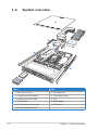
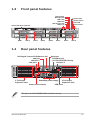
ESC4000 G2
Configuration Guide
E7580
First Edition V1
July 2012
Copyright © 2012 ASUSTeK COMPUTER INC. All Rights Reserved.
No part of this manual, including the products and software described in it, may be reproduced, transmitted,
transcribed, stored in a retrieval system, or translated into any language in any form or by any means,
except documentation kept by the purchaser for backup purposes, without the express written permission
of ASUSTeK COMPUTER INC. (“ASUS”).
ASUS provides this manual “as is” without warranty of any kind, either express or implied, including but not
limited to the implied warranties or conditions of merchantability or fitness for a particular purpose. In no
event shall ASUS, its directors, officers, employees, or agents be liable for any indirect, special, incidental,
or consequential damages (including damages for loss of profits, loss of business, loss of use or data,
interruption of business and the like), even if ASUS has been advised of the possibility of such damages
arising from any defect or error in this manual or product.
Specifications and information contained in this manual ae furnished for informational use only, and are
subject to change at any time without notice, and should not be construed as a commitment by ASUS.
ASUS assumes no responsibility or liability for any errors or inaccuracies that may appear in this manual,
including the products and software described in it.
Product warranty or service will not be extended if: (1) the product is repaired, modified or altered, unless
such repair, modification of alteration is authorized in writing by ASUS; or (2) the serial number of the
product is defaced or missing.
Products and corporate names appearing in this manual may or may not be registered trademarks or
copyrights of their respective companies, and are used only for identification or explanation and to the
owners’ benefit, without intent to infringe.
ii
Contents
Revision history........................................................................................... iii
Safety information....................................................................................... iv
Chapter 1:
Product introduction
1.1
Key features................................................................................... 1-2
1.3
Front panel features...................................................................... 1-5
1.2
1.4
1.5
System overview........................................................................... 1-4
Rear panel features....................................................................... 1-5
System specifications.................................................................. 1-6
Chapter 2:
Components
2.1
Upgrading CPU and CPU heatsink.............................................. 2-2
2.3
Upgrading hard disk drives.......................................................... 2-4
2.2
2.4
2.5
2.6
2.7
2.8
Upgrading system memory.......................................................... 2-3
Installing ASUS PIKE RAID module............................................ 2-5
NVIDIA® Tesla™ GPU computing modules................................ 2-7
Installing optical drive.................................................................. 2-8
Friction rail kit............................................................................... 2-9
OS support list............................................................................ 2-10
Revision history
Revision
Revision history
Date
V1
First release of ESC4000 G2 configuration guide
July 2012
iii
Safety information
Electrical Safety
•
•
•
•
Before installing or removing signal cables, ensure that the power cables for
the system unit and all attached devices are unplugged.
To prevent electrical shock hazard, disconnect the power cable from the
electrical outlet before relocating the system.
When adding or removing any additional devices to or from the system, contact
a qualified service technician or your dealer. Ensure that the power cables for
the devices are unplugged before the signal cables are connected. If possible,
disconnect all power cables from the existing system before you service.
If the power supply is broken, do not try to fix it by yourself. Contact a qualified
service technician or your dealer.
Operation Safety
•
•
•
•
•
Servicing of this product or units is to be performed by trained service
personnel only.
Before operating the server, carefully read all the manuals included with the
server package.
Before using the server, make sure all cables are correctly connected and the
power cables are not damaged. If any damage is detected, contact your dealer
as soon as possible.
To avoid short circuits, keep paper clips, screws, and staples away from
connectors, slots, sockets and circuitry.
Avoid dust, humidity, and temperature extremes. Place the server on a stable
surface.
This product is equipped with a three-wire power cable and plug for the user’s
safety. Use the power cable with a properly grounded electrical outlet to avoid
electrical shock.
Lithium-Ion Battery Warning
CAUTION! Danger of explosion if battery is incorrectly replaced.
Replace only with the same or equivalent type recommended by the
manufacturer. Dispose of used batteries according to the manufacturer’s
instructions.
CD-ROM Drive Safety Warning
CLASS 1 LASER PRODUCT
Heavy System
CAUTION! This server system is heavy. Ask for assistance when moving or
carrying the system.
iv
This chapter describes the key features
of ESC4000 G2. It includes the product
overview and general specifications.
Product introduction
Chapter 1
1.1
Key features
ASUS ESC4000 G2 is the latest high-density GPU server based on dual Intel
Xeon E5-2600 processor platform, featuring eight hot-swap 3.5” SATA HDD cages,
1+1 80+ Platinum 1620W redundant power supply and nine PCI-E Gen3 x16
expansion slots. It delivers high density computing power, scalable expansion
capability, intelligent thermal solution and green design, making it an ideal choice
for applications in the HPC field of life and medical science, engineering science,
financial modeling and virtualization.
8+1 Flexible Expansion Slots
The ESC4000 supports up to eight PCI-E Gen3 x16 slots for high expandability,
compatible with versatile expansion cards. In addition, there is an optional riser for
a low profile/half-length card and PIKE solution.
Intelligent System Fan Control II Function
To improve heat-dispersion and a stable computing environment, independent
smart fans provide cooling for each area of the GPU and CPU, and a dual-fan
design for GPU cards provides an extra thermal back-up solution.
1+1 Redundant PSU (1620W 80+ Platinum)
The ESC4000 is equipped with a 1620W 80+ Platinum level redundant power
supply with power efficiency up to 94% for energy savings, while the hot swappable
design reduces power loss, improves power efficiency and saves more TCO for
users.
Comprehensive RAID Solutions
The ESC4000 supports the optional ASUS RAID PIKE upgrade kit. With only a
PIKE riser card and a PIKE card, upgrade the server from a SATA to SAS based
storage system by re-connecting the cable from the onboard SATA to a PIKE riser
SAS port. Users now have flexible choices for multiple storage options!
Complete Server Remote Management Solution
By installing an optional Web GUI ASMB6-iKVM module, users can have full
control of the server with an out-of-band server-based management (IPMI 2.0
standard) and 24x7 real-time remote monitor. Meanwhile, ASWM Enterprise
software provides one-to-multiple centralized management including BIOS flash,
remote control, power control and asset management through a user-friendly
interface. Users can utilize an effective tool with a user-friendly interface to control
the servers remotely.
1-2
Chapter 1: Product introduction
Cutting-edge Architecture
The ESC4000 G2 supports dual CPUs from the Intel® Xeon® E5-2600 processor
family and with 16 DIMM sockets onboard, up to 512GBof four-channel DDR3
1600/1333 memory is supported. Combined, they provide for a high computing
capability that can tackle the most difficult of tasks. Additionally, there are more
PCI-E lanes with PCI-E Gen 3 support, which is suitable for systems that require
high I/O connectivity and bandwidth and supports more PCI-E devices.
ASUS ESC4000 G2
1-3
1.2
System overview
10
3
4
9
5
7
8
6
11
11
2
1
Items
Items
1. Hard disk drive bay
2. Hard disk drive
3. Computing module bracket
4. Computing module
5. Computing module airduct
6. CPU
7. CPU heatsink
8. DDR3 DIMM
9. PCI-E 2.0/3.0 x16 riser card
10. Top cover
11. Friction rackmount rail kit
1-4
Chapter 1: Product introduction
1.3
Front panel features
Reset button
Message LED
LAN1 LED
LAN2 LED
HDD Access LED
USB ports
Optical disk drive (optional)
Location LED
Location switch
Power LED
Power button
2
HDD 1
1.4
HDD 5
HDD 2
HDD 6
HDD 3
HDD 7
1
HDD 4
HDD 8
Rear panel features
Half-length/ Low-profile Expansion slot
VGA port
LAN port 2
LAN port 1
4 Full-length
Expansion slots
Serial port
InfiniBand port
(for ESC4000/FDR G2 only)
LAN port 3*
Redundant power supply
Power cord connector
4 Full-length
Expansion slots
USB ports
*The port is for ASUS ASMB6-iKVM controller card only.
ASUS ESC4000 G2
1-5
1.5
System specifications
Model Name
ESC4000/FDR G2
ESC4000 G2
2 x Socket-R LGA2011
Intel® Xeon® E5-2600 product family
QPI 6.4 / 7.2 / 8.0 GT/s
Intel® C602 chipset
Mellanox Connectx-3
Intel® C602 chipset
MT27514A0-FCCR-FV FDR
56Gbps controller
Processor / System Bus
Core Logic
ASUS Features
Fan Speed
Control
ASWM
Enterprise
Total Slots
√
√
Capacity
Memory
Memory Type
Memory Size
Total PCI/PCI-X/
PCI-E Slots
Expansion Slots
Slot Type
Additional Slot
Storage
SATA Controller
16 (4-channel per CPU, 8 DIMMs per CPU)
Maximum up to 128GB (UDIMM)
Maximum up to 512GB (RDIMM)
Maximum up to 512GB (LRDIMM)
DDR3 800/1066/1333/1600 RDIMM
DDR3 1066/1333/1600 ECC UDIMM Non-ECC UDIMM
DDR3 1066/1333 LR-DIMM
1GB, 2GB, 4GB, 8GB, 16GB, 32GB* (RDIMM)
1 GB, 2GB, 4GB, 8GB* (UDIMM)
8GB, 16GB, 32GB* (LRDIMM)
9
Full-length/Full-height
-8 x PCI-E 3.0 x16 (4 at x16 Link or 8 at x8 Link)
(Slot CPU1_PCIE2, CPU1_PCIE4, CPU2_PCIE1,
CPU2_PCIE3 auto switch to x8 Link if slots CPU1_PCIE1,
CPU1_PCIE3, CPU2_PCIE2, CPU2_PCIE4 are occupied)
Half-length / Low-profile
-1 x PCI-E 3.0 x16 (Gen3 x8 Link) (PIKE SAS Card for
Storage Enhancement)
PIKE Riser Card
Intel® C602-A:
<AHCI>
- 2 x SATA 3Gb/s ports; 2 x SATA 6Gb/s ports
- Intel® RSTe (for Windows only)
- Supports software RAID 0, 1, 5 & 10
- LSI MegaRAID (for Linux / Windows)
- Supports software RAID 0, 1 & 10
<SCU>
- 4 x SATA 3Gb/s ports
- Intel® RSTe (for Windows only)
- Supports software RAID 0, 1, 5 & 10
(continued on the next page)
1-6
Chapter 1: Product introduction
Model Name
Storage
HDD Bays
Networking
Graphic
SAS
Controller
I = Internal
A or S will be
hot-swappable
LAN
VGA
Auxiliary Storage Device Bay
(Floppy / Optical Device)
Onboard I/O
OS Support
Anti-virus Software
Out of Band
Remote
Management
Hardware
Solution
Software
Dimension (HH x WW x DD)
Net Weight Kg (CPU, DRAM &
HDD not included)
Power Supply
Power Rating
Environment
ESC4000/FDR G2
ESC4000 G2
Optional:
ASUS PIKE 2008 8-port SAS 6G RAID card
ASUS PIKE 2008/IMR 8-port SAS 6G RAID card
ASUS PIKE 2108 8-port SAS 6G H/W RAID card
8 x Hot-swap 3.5” HDD Bays
2 x Intel 82574L Gigabit LAN + 1 x Mgmt LAN
Aspeed AST2300 / 16MB
1 x slim-type Optical Device Bay
(Options: No Device / DVD-RW*)
*DVD-RW default for North America
1 x External Serial Port
3 x RJ-45 ports (1 for ASMB6)
4 x USB 2.0 ports (Front x 2, Rear x 2)
1 x Internal A Type USB Port
1 x VGA port
1 x QSFP Port
Windows® Server 2008 R2
Windows® Server 2008 R2 Enterprise
Windows® Server 2008 Enterprise 32 / 64-bit
Windows® Server 2003 R2 Enterprise 32 / 64-bit
RedHat® Enterprise Linux AS5.7/6.2 32 / 64-bit
SuSE® Linux Enterprise Server 11.2 32 / 64-bit
CentOS 5.7/6.2 32/64-bit
VMWare ESX4.1/ESXi4.1
(Subject to change without any notice)
Optional Anti-virus Software CD
ASMB6-iKVM for KVM-over-Internet
ASUS ASWM Enterprise
750mm x 444mm x 88mm (2U)
19 Kg
1 + 1 Redundant 1620W (80+) Platinum Power Supply
(Following different configurations by region.)
Input:
1000W: 100—120 Vac, 12-10A
1200W: 120—140 Vac, 12—10A
1620W: 180—240Vac,10.5—8A
50—60Hz Class I
Operating temperature: 10°C–35°C /
Non operating temperature: -40°C–70°C
Non operating humidity: 20%–90% ( Non-condensing)
*Specifications are subject to change without notice.
ASUS ESC4000 G2
1-7
1-8
Chapter 1: Product introduction
This chapter lists the key components
and optional accessories for the server
system.
Components
Chapter 2
2.1
Upgrading CPU and CPU heatsink
The motherboard comes with two surface mount LGA 2011 Socket R designed for
the Intel® Xeon® E5-2600 series processor family.
8
HD
Db
1
2
ay s
ide
3
7
5
4
Rea
6
r sid
e
Order P/N
•
To prevent damage to the socket pins, do not remove the PnP cap unless
you are installing a CPU.
•
The CPU fits in only one correct orientation. DO NOT force the CPU into
the socket to prevent bending the connectors on the socket and damaging
the CPU!
•
To prevent contaminating the paste, DO NOT spread the paste with your
finger directly.
Description
90-S000U0CP0T E5-2690 2.9G (8C/20M/135W/DDR3 1600/HT/8.00 GT) with Heatsink
90-S000U0C90T E5-2680 2.7G (8C/20M/130W/DDR3 1600/HT/8.00 GT) with Heatsink
90-S000U0C87T E5-2670 2.6G (8C/20M/115W/DDR3 1600/8.00 GT) with Heatsink
90-S000U0C88T E5-2665 2.4G (8C/20M/115W/DDR3 1600/8.00 GT) with Heatsink
90-S000U0C89T E5-2660 2.2G (8C/20M/95W/DDR3 1600/8.00 GT) with Heatsink
90-S000U0C8AT E5-2650 2.0G (8C/20M/95W/DDR3 1600/8.00 GT) with Heatsink
90-S000U0C8BT E5-2640 2.5G (6C/15M/95W/DDR3 1333/7.20GT) with Heatsink
90-S000U0C8CT E5-2630 2.3G (6C/15M/95W/DDR3 1333/7.20GT) with Heatsink
90-S000U0C8DT E5-2620 2.0G (6C/15M/95W/DDR3 1333/7.20GT) with Heatsink
2-2
Chapter 2: Components
2.2
Upgrading system memory
The motherboard comes with sixteen (16) Double Data Rate 3 (DDR3) Dual Inline
Memory Modules (DIMM) sockets.
1
2
3
4
DIMM_A1
DIMM_A2
1 2
3 4
DIMM_B1
DIMM_B2
5 6
7 8
13 DIMM_G1
14 DIMM_G2
15 DIMM_H1
5
6
7
8
16 DIMM_H2
13
DIMM_D2
DIMM_D1
DIMM_C2
DIMM_C1
9 DIMM_F2
14
15
16
10 DIMM_F1
9
10
11 DIMM_E2
11
12 DIMM_E1
12
You may install 1 GB, 2 GB, 4 GB, 8 GB, 16 GB, and 32 GB registered DDR3
DIMMs with ECC or 1GB, 2GB, 4GB, and 8GB unbuffered DDR3 DIMMs with ECC/
Non-Ecc into the DIMM sockets using the memory configurations in this section.
CPU1 Configuration
A2 A1 B2 B1 C2 C1 D2 D1
1 DIMMs
•
2 DIMMs
•
4 DIMMs
8 DIMMs
•
•
•
•
•
•
•
•
•
•
•
•
•
CPU1 + CPU2 Configuration
A2 A1 B2 B1 C2 C1 D2 D1 E2 E1 F2 F1 G2 G1 H2 H1
1 DIMMs
•
2 DIMMs
•
•
4 DIMMs
•
•
8 DIMMs
•
•
12 DIMMs
•
•
•
•
16 DIMMs
•
•
•
•
•
•
•
•
•
•
•
•
•
•
•
•
•
•
•
•
•
•
•
•
Order P/N
Description
90-S000I0610T
DDR3 1600 ECC REG 8G 240P
90-S000I0620T
90-S000I0600T
ASUS ESC4000 G2
•
•
•
•
•
•
•
•
DDR3 1600 ECC REG 16G 240P
DDR3 1600 ECC REG 4G 240P
2-3
2.3
Upgrading hard disk drives
The system supports eight hot-swap SATAII/SAS hard disk drives. The hard disk
drive installed on the drive tray connects to the motherboard SATAII/SAS ports via
the SATAII/SAS backplane.
We recommend that you install identical drives of the same model and capacity
for RAID configuration.
2-4
Order P/N
Description
90-S000H64R0T
300GB 6G SAS15Krpm with HDD Tray (Seagate)
90-S000H64S0T
450GB 6G SAS15Krpm with HDD Tray (Seagate)
90-S000H64T0T
600GB 6G SAS15Krpm with HDD Tray (Seagate)
90-S000H65D1T
500GB SATA3 6Gb 7200 rpm with HDD Tray (Seagate)
90-S000H65B1T
1TB SATA3 6Gb 7200 rpm with HDD Tray (Seagate)
90-S000H65V0T
500GB SATA3 7200 rpm with HDD Tray (Seagate Enterprise)
90-S000H65U0T
1TB SATA3 7200 rpm with HDD Tray (Seagate Enterprise)
90-S000H65T0T
2TB SATA3 7200 rpm with HDD Tray (Seagate Enterprise)
90-S000H65E2T
3TB SATA3 7200 rpm with HDD Tray (Seagate Enterprise)
Chapter 2: Components
2.4
Installing ASUS PIKE RAID module
Follow the steps below to install the optional ASUS PIKE SAS RAID card to the
ASUS PIKE riser card.
1
4
2
3
7
6
ASUS ESC4000 G2
5
2-5
1.
2.
3.
4.
5.
6.
7.
Remove the screws that secure the riser card bracket.
Hold the riser card firmly then pull it upward to detach it from the PCI Express
x16 slot on the motherboard.
Remove the SATA/SAS cables from the onboard SATA connectors then
connect them to the SAS1-8 connectors on the PIKE riser card.
Connect the SGPIO1 cable from the SGPIO1 connector into the SGPIO2
connector on the riser card.
Align and insert the golden fingers of the PIKE RAID SAS card into the card
slot of the riser card. Ensure that the PIKE RAID SAS card is seated firmly
into the slot.
Align the golden fingers of the riser card bracket with the PCI Express x16
slot on the motherboard then push it firmly into place. Ensure that the riser
card bracket is aligned with the rear panel.
Secure that riser card bracket with the screws that you removed in step 1.
If you are using a PIKE 1078 SAS RAID card, snap the iButton into the
iButton slot on the riser card.
Order P/N
Description
90-S00CS0150T PIKE 2108 8-port SAS 6G card. RAID Kit (H/W RAID 0, 1, 10, 5, 6, 50, 60)
90-S00CS0140T PIKE 2008/IMR 8-port SAS 6G card. RAID Kit (RAID 0, 1, 10, 5, 50)
90-S00CS0130T PIKE2008 8-port SAS 6G card. RAID Kit (RAID 0, 1, 10, 1E)
2-6
Chapter 2: Components
2.5
NVIDIA® Tesla™ GPU computing
modules
Follow the steps below to install the optional NVIDIA® Tesla™ GPU computing
modules to the system.
10
1
7
6
4
3
5
8
9
11
2
Order P/N
Description
90-S000R1M00T
TESLA C2075 6GB GPU CARD
90-S000R1M10T
TESLA M2075 6GB GPU CARD
90-S000R00D0T
TESLA M2090 6GB GPU CARD
90-S000R0080T
GRAPHIC CARD QUADRO 400
90-S000R0070T
GRAPHIC CARD QUADRO 600
90-S000R0090T
GRAPHIC CARD QUADRO 2000
90-S000R00A0T
GRAPHIC CARD QUADRO 4000
90-S000R00B0T
GRAPHIC CARD QUADRO 5000
90-S000R00C0T
GRAPHIC CARD QUADRO 6000
ASUS ESC4000 G2
2-7
2.6
Installing optical drive
1
2
3
2-8
Order P/N
Description
90-S000C4000T
SLIM DVD-ROM 8X MODULE
90-S000C2000T
SLIM DVD-RW MODULE
Chapter 2: Components
2.7
Friction rail kit
Front end
Rack rails
Rear end
1
2
3
Order P/N
90-S00SP1360T
ASUS ESC4000 G2
Description
FRICTION RAIL KIT V2.0
2-9
2.8
OS support list
OS support list
Windows® Server 2008 R2
Windows® Server 2008 R2 Enterprise
Windows® Server 2008 Enterprise 32/64-bit
Redhat® Enterprise Linux AS 5.7/6.2 32/64-bit
SuSE® Linux Enterprise Server 11.1 32/64-bit
CentOS 5.7/6.2 32/64-bit
VMWare ESX4.1/ESXi4.1
2-10
Order P/N
Description
90-S00SW7140T
Windows® Server 2008 STD 64-bit ENG
90-S00SW7150T
Windows® Server 2008 STD 64-bit TCH
Chapter 2: Components