1
PRODUCT No.23900
ASAHI PENTAX
SERVICE MANUAL
ENGLISH
23900
ME
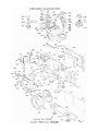
Disassembly Procedure
1. Self-timer charge lever assembly (0-A118)—Self-timer screw left-handed (A122)
— 231K-H50
2. Body Covering, left and right (A19, A20)
3. Install self-timer lever assembly (0-A118) temporarily.
4. Bottom cover assembly (A400) — CSS 1.7 x 2.8 x 3
Connector seat (A23), R button (C117)
5. Winding lever assembly (0-C69)
Cover screw (C139) — 23600K-C135-A (left handed)
Winding lever nut (C8) — 23600K-C134-A2
Cover ring (A321)
6. Shutter dial
Shutter dial at AUTO
Loosen set screw (A319) — Shutter dial (A316)
Release pin (A313) — Release button (A317)
7. Rewinding knob
R
Rewinding knob assembly (0-D6) — Nut (D15) - Washer (D21)
- ASA dial assembly (0-D11-01)
23600k-D4-A2
8. Top cover assembly (A300) - 4 screws - cover frame (A131)
9. Unsolder 12 lead wires and one contact piece
Take out lead wires from cord holder
Lead wire No. 21 (K100), No. 24 (T100), No. 22 and No. 23 (T100),
No. 19 and No. 20 (N4), No. 15, No. 16, No. 17, No. 18 and one
Contact piece (A129), No. 26 and No. 27 (0-A21).
10. ASA volume assembly (R100) - Top cover screw (A16) - CNL-d 1.7 x 2.5
11. Hot shoe contact piece (N4)
12. P.C. board retainer (I1) - W14
13. P.C. board retainer plate (N5) - T-CNS 1.7 x 5
14. LED retainer screw - CNL-D 1.4 x 2 - W31
15. P.C. board assembly (T100)
16. Front board and mirror housing
Cocking the shutter
Removing 5 screws - W14
Shutter light seal cover (A8)
17. Bulb actuator plate (A504) - CNL-D 1.4 x 2
18. Cocked indicator assembly (0-C23)
SW actuator lever shaft (C49)
23900
Page 1 of 15
19. Counter dial
Back cover open
Counter dial spring (C57) - Counter retainer plate (C25),
Counter dial assembly (0-C34)
Come off transporting claw spring (C65)
Remove (C146) (C53) and CNS 1.7 x 3
Winding seat assembly (0-C2) - (0-C5) - (C7)
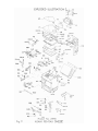
20. Shutter block (S000) - CNL-D 1.7 x 3 x 3
21. Bottom release assembly (0-C147)
Winding up little from bottom part with tool (23900K-C207-A)
To remove retainer screws of (0-C147).
22. Release plate assembly (A500)
Guide screw (A507) - Release plate restitution spring (A510).
When removing (A500), detach hook lever (C108) from (A500)
23. Shutter charge lever assembly (0-C129)
Loosening joint (C207) with tool (23900K-C207-A), remove (0-C129)
and (C144).
Fasten joint (C207) again.
24. Winding guide plate assembly (0-C102)
25. R lever assembly (0-C105)
LW-13 - (0-C105) - (C126)
(C145) - LW13 - (C144) - (C107) - (C130) - W14 - (C108) - W8 - (C125)
(C207) - (0-C106) - (0-C12).
26. Back cover assembly (0-C26)
27. Winding stopper assembly (0-C26)
28. Winding shaft assembly (0-C22) - Main gear (C30)
29. Sprocket shaft pin (C40) - Loosening set T 1.7 x 1.6
30. Top mec. Plate assembly (0-C1) - (C146) x 2 - CSS 1.7 x 3
31. Spool cam assembly (0-C202) and spool assembly (0-C204)
- W17 (t=0.2mm)
23900
Page 2 of 15
Assembly Procedure
1. Spool assembly (0-C204) and spool cam assembly (0-C202)
W17 (t=0.2mm)
2. Top mec. Plate assembly (0-C1)
Pulling back transport indicator
3. Sprocket shaft pin (C40)
Apply screw lock on Set T 1.7 x 1.6
4. Winding shaft assembly (0-C22) - Main gear (C30)
5. Winding stopper assembly (0-C26)
6. Winding spring assembly (0-C12)
Proper tension of the spring is shown in figure.
After installing (0-C12), install (0-C106) and (C207) temporarily.
- 23900K-C207-A
7. Perforation adjustment - Tool 23102-C57-A
Same adjustment with K2 camera.
Choosing proper 2nd gear (C31).
8. Bottom mechanism
a) (C125) - W8 (t=0.1) - Winding hook lever (C108) - W14 (t=0.05, 0.1) (C130) - Winding lever ratchet (C107) - LW13 - (C145)
b) (C126) - R lever assembly (0-C105) - LW13
c) Winding guide plate assembly (0-C102) - (C146) - CSS 1.7 x 2.5 - CNS 1.7 x 3
d) Shutter charge lever assembly (0-C129)
Loosening (C207) - (C144) - (0-C129) - fastening (C207)
When fastening (C207), winding shaft should be in the wound position, at
the same time, mirror charge lever (0-C102) should be moved to a correct
position
9. Shutter release plate
Release plate restitution spring (A510)
(Take care to install spring in correct direction)
Release plate assembly (A5000
(Take care not to bend winding hook lever (C108).)
Guide screw (A507), connection spring (A511)
(Engaging (A510) to (A500).)
10. Bottom release assembly (0-C147) - CNM 1.7 x 2.2, CNM 1.7 x 2.8
Winding shutter a little
23900
Page 3 of 15
11. Shutter block (E000) - CNL-D 1.7 x 3 x3
Light seal plate (A8)
12. Bulb actuator plate (A504) Temporary installation
- CNL-D 1.4 x 2
13. Back cover assembly (A200)
14. Winding seat assembly (0-C2) - (C53), (C146), CNS 1.7 x 3
Install (0-C2) with back cover open
Winding lever click cam assembly (0-C5)
Winding lever friction spring (C7)
Engage transporting claw spring (C65)
15. Counter transporting adjustment
a) Check the function of counter dial stopper lever (C4) and transporting
claw assembly (C18).
b) If the vertical black lever of (0-C26) is bent forward, bend it straight.
c) Adjust the counter transporting function using the temporary counter
transporting gear (C34).
When back cover is closed, receiving claw (C16) and transporting claw (C18)
should be engaged to the first tooth of (C34) simultaneously with enough
gearing portion. Bend the tip of the claw which couples with the gear (C34),
If not enough gearing portion.
When back cover is opened, claw tip of (C16) must detach from the gear (C34)
with a clearance of about 0.5mm.
If there is not enough clearance, bend the other end of (C16) opposite from
the claw as shown in the figure.
16. Counter dial
Counter dial assembly (0-C34)
Counter dial spring (C57)
Counter retainer plate (C25)
(C25) is installed in left side gutter as shown in figure.
Give the spring (C57) 1/2 or 3/4 turns of tension.
17. Bulb off adjustment (Winding lever is at pre-advance position.)
After releasing the first curtain, adjust "B" off position with eccentric
screw riveted on bulb actuator plate (A504). When shutter rod comes back,
0.2mm clearance is necessary after releasing the 2nd curtain.
23900
Page 4 of 15
18. Cocked shutter assembly (0-C23) - SW actuator lever shaft.
19. Main SW adjustment = (I200)
When shutter actuator plate is held in "ON" position, 0.2mm clearance is
necessary between longer contact piece of main SW and insulation blue
collar.
To adjust the clearance, bend the shorter contact piece.
When both contact pieces touch each other, and the shorter contact piece
is pulled down, the longer one should be down also as the shorter one does.
If there is not enough tension on the longer contact piece, it may show
uneven shutter speed.
When winding lever is at closed position, 0.2mm clearance is necessary
between both contact pieces.
20. Front board and mirror housing
When the above mentioned parts are installed, shutter block (E000) should
be cocked but not charge mirror housing.
Put on W14 (0.1mm) underneath front board and fasten it with (A132),
pushing down left. Confirm the function of self-timer, shutter mechanism
and mechanical back.
21. Parallax adjustment
22. P.C. board pattern assembly (T100)
(I1) - CNL-D 1.7 x 2.5 - (N5) - T-CNS 1.7 x 5 - (N4) - (N6 x 2)
23. ASA volume assembly (R100) - (A16) - CNL-D 1.7 x 2.5
24. Soldering 13 lead wires
25. Bottom cover assembly (A400) - (A23) - (C117)
26. LED positioning adjustment
27. Temporary top cover and installing ASA dial assembly (0-D11-01) and winding
lever temporarily.
28.
a) Shutter speed adjustment - VR-A
ASA 100, X1, f8, (KA-00-1A), 2.8V
EV12 - 1/60
EV16 - 1/1000
EV8
- 1/4
23900
Page 5 of 15
b) LED indication adjustment
High EV (EV12), EV16)
Low EV (EV8)
-
VR-B
VR-C
c) Battery checker - VR-D
2.45V - Turning on and off (flickering)
2.55V - Turning on
d) VR-E is prohibited to adjust
29. Counter indication (C15) - (A300)
30. Top cover
(A131) - (A300)
Set shutter dial at "B"
Shutter restriction lever is set at left (viewing from back)
Put on top cover softly and fix it turning shutter dial to AUTO position
Four retainer screws
Rewinding parts, shutter dial, winding lever, etc.
31. Shutter stroke adjustment
a) Set shutter dial at "B"
b) 0.2mm clearance is necessary after releasing shutter.
Adjust the shutter stroke with eccentric screw.
32. X Synchronization with self-timer operation at "B"
When camera is operated with self-timer operation at "B" position,
exposure time should be adjusted around 11~13ms.
To adjust the exposure time, bulb actuator plate (A504) should be moved
up or down with eccentric screw.
Also check shutter dial 100X with self-timer operation in the same manner.
If camera is not adjusted as mentioned above, it is impossible to take
pictures with complete synchronization with electronic flash, especially in
the following combination such as shutter dial at 100X, winding lever at
closed position and with self-timer operation.
33. Focusing
23900
Page 6 of 15
34. Body covering, self-timer lever assembly (0-A118)
Self-timer screw (A122) - left-handed.
35. Disassembly of front board and mirror housing
a) Remove self-timer (H000)
b) Mirror release lever (0-A111)
c) Mirror housing
d) Connector (I100) - only loosening (I2)
e) Unsolder 5 lead wires
Purple 2, orange 2, black 1
36. SWg, SWm located underneath mirror housing
SWg = Magnet switch
SWm = Memory switch
a) SWg - Spring tension adjustment
8~10g spring tension is desirable: Check with tension gauge.
b) SWm adjustment
Bend longer contact piece as shown in figure.
Shorter contact piece should have proper tension.
(Check the tension after charging the mirror housing.)
c) SWg adjustment
When mirror housing is charged, 0.2~0.3mm clearance is necessary
between both contact pieces.
Bend longer contact piece as shown in figure.
23900
Page 7 of 15
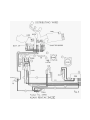
37. Adjustment of SWm and SWg
Time lag sequence of SWm and SWg
To check the time lag, an oscilloscope is necessary.
The time lag is determined by the variation in voltage when
SWm and SWg turn "ON" and "OFF".
Here is one example for time lag check with a single-trace oscilloscope.
Adapter should be made as shown below.
Adapter is connected to mirror housing connector and oscilloscope.
After charging the mirror housing and releasing it to put the mirror in
the "up" state, time lag appears on the oscilloscope screen.
The adjustment procedures can be referred to in item 36.
23900
Page 8 of 15
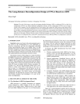
PENTAX ME
Notes and Troubleshooting Tips
FIGURES:
Fig.
Fig.
Fig.
Fig.
Fig.
Fig.
Fig.
Fig.
Fig.
1
2
3
4
5
6
7
8
9
-
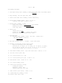
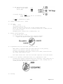
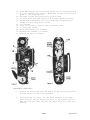
Top cover removed
Bottom cover removed
Front of camera, wind side
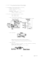
Front view, mirror box removed
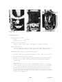
Bottom of mirror box
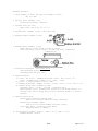
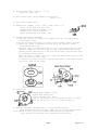
Current style, mirror switches
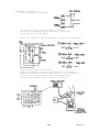
Circuit for testing mirror switches
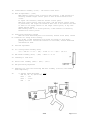
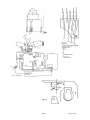
Wiring diagrams
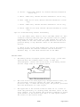
Modified bottom cover
ADJUSTMENT LOCATIONS:
Auto speeds
Meter readout, high light
Meter readout, low light
Battery test
Release overtravel
Mechanical speed
Travel time, 1st blade
Travel time, 2nd blade
Trigger switch (fast speed)
Magnet switch
A
B
C
D
E
F
G
H
I
J
Fig.
Fig.
Fig.
Fig.
Fig.
Fig.
Fig.
Fig.
Fig.
Fig.
1
1
1
1
3
4
4
4
4
5
ADJUSTMENT VALUES:
Blade travel time:
Flange-focal distance:
Release overtravel:
Mechanical speed:
Battery test:
Memory time lag:
6ms (20mm distance)
45.46mm (flange to film guide rails)
0.2mm additional travel of release slide after
shutter releases
11ms to 13ms exposure time when operated with
self-timer action at bulb setting
Viewfinder LEDs to light steadily with 2.55V
supplied and to flash on and off at 2.45V
Magnet switch SWg to close 10ms after memory
switch SWm opens
23900
Page 9 of 15
ADJUSTMENT SEQUENCE:
1. Auto speeds
Variable resistor A set: ASA 100, X1 compensation, f/8. With 2.8V
supplied to the battery compartment, the shutter should deliver the
following shutter speeds ath the indicated light levels:
EV12 1/60 second
EV16 1/1000 second
EV8
1/4 second
2. Meter Readout
EV 12 and 16
Adjust variable resistor B
EV8
Adjust variable resistor C
Later versions of the flex circuit board have only one meter readout
adjustment, Fig. 8.
3. Battery test
Adjust variable resistor D for proper operation. Later versions of
the flex circuit do not have the batery test adjustment. It is then
only necessary to make an operational check.
AVOID DISTURBING:
Variable resistor VR-E on the menory circuit board (not
accessible until the flex circuit has been removed). In some
versions of the flex circuit, VR-E is at the top of the camera.
DISASSEMBLY HIGHLIGHTS:
Control positions:
Speed selector
Film speed
Auto
Unimportant
Location of left-hand threads:
Winding lever cap screw
Winding lever retaining nut
Self-timer lever screw
Sequence:
1.
Bottom cover (Loose parts: cover for power winder terminals and
rewind button)
2.
Top cover (Remove black ring at top of speed selector; top cover
screw is then accessible through hole in speed selector)
3.
Unsolder film speed resistor wires (two yellow) from flex
circuit and from diaphragm resistor (if you're just removing the
flex circuit, unsolder only the film-speed resistor wire that
connects to the flex circuit)
4.
Film-speed resistor (not necessary if you're just removing the
flex circuit)
5.
Unsolder red wires from flex circuit
6.
screws holding hot shoe contact above eyepiece
7.
Screw and clip that hold down photocell circuit board
8.
Screw and circuit board retainer at rewind-side of camera
9.
Screw and washer holding LED display at wind-lever side
23900
Page 10 of 15
10. Slide LED display out of focusing screen slot at wind-lever side
11. Lift out complete flex circuit (Underside of flex circuit may be
glued to top of pentaprism)
12. Unsolder 5 leads form front-plate circuit board
13. Unsolder green wire and blue wire from power winder terminals
14. Rewind-side leatherette; peel back wind-side leatherette far
enough to reach front plate screws
15. Cock shutter
16. Screw at top rear of mirror cage, wind-lever side
17. 4 front-plate screws
18. Front-plate/mirror-box assembly
19. Winding-seat assembly (3 screws)
20. Shutter assembly (3 screws)
REASSEMBLY HIGHLIGHTS:
1.
Replace the mirror-box with the mirror in the released position
and the shutter in the cocked position
2.
To replace the top cover, set the speed selector to the Bulb
("B") position and the wind-lever shaft to the closed position.
Then seat the top cover and turn the speed selector to the auto
setting.
23900
Page 11 of 15
TROUBLESHOOTING:
Typical battery drain
Meter:
1.7-2.0mA
Shutter open:
10mA
Behaviour with batteries
Fastest speed only except at mechanical shutter settings
Replacement parts
Circuit board T100 and Seiko shutter E000 available from Pentsx
only as complete modules; other parts available individually
Troubleshooting steps for specific problems
1.
Shutter gives only mechanical speed at auto, LEDs don't turn on
Battery voltage at flex circuit
Check for +3V between ground and each red wire at top of flex
circuit. No voltage: check battery box and red wire solder
connections.
Main switch
Check for +3V at center lead (uninsulated connector) to frontplate circuit board A129 with release-side partially depressed.
No voltage: check main switch for poor contact. You can also
check the main switch by shorting between the red wire at the
flex circuit and the center terminal at the front-plate circuit
baord. The short should turn on the meter. If it does, the main
switch is the problem.
23900
Page 12 of 15
2.
Auto-exposure erratic, shutter sometimes delivers mechanical
speed only.
Memory time lag
Chattering in magnet switch
Check the timing between the magnet switch and the memory switch
by plugging the modified circuit board (Fig. 7) into the mirrorbox connector I100. Power the special circuit board with a 6V DC
power supply. Then measure across the switch with an
oscilloscope as you release the mirror-box. You should measure a
time lag of 10-12ms between the moment the memory switch opens
and the moment the magnet switch closes. Adjust the time lag by
reforming the long blade of the magnet switch at the point
indicated in Fig. 5. The oscilloscope test also allows you to
see chattering in the magnet switch.
3.
Shutter delivers only fastest speed at auto, LEDs operate OK
Electromagnet
Check the continuity of the electromagnet coil between the blue
wire and brown wire at the front-plate circuit baord. You should
measure approximately 350 Ohms.
Magnet switch SWg
The magnet switch (Fig. 5) should close as the diaphragm-closing
lever starts to move down. You should them measure direct
continuity between the orange wire and the black wire (Fig. 7).
To check the magnet switch without removing the mirror-box, you
can use the modified circuit board shown in Fig. 7. From the top
of the camera, proceed with the disassembly far enough to lift
out the memory circuit baord. Check for direct continuity
between the orange-wire connection anf the black-wire connection
with the shutter held open on Bulb. No continuity: Magnet switch
is not closing.
4.
Power winder transports film during exposure
Winder sync switch
Check the continuity between the green-wire poser winder
terminal (Fig. 2) and ground. You should measure direct
continuity with the shutter open, indicating that the winder
sync switch (Fig. 5) has closed.
Malfunctions resulting from poor solder connections or poor poor
contact at mirror-box connectio I100
1. Violet - LEDs work, shutter hangs open or delivers slow speed
2. Orange - LEDs work but continue to charge with mirror up
Shutter delivers mechanical action only
3. Violet - LEDs work, shutter hangs open or delivers slow speed
23900
Page 13 of 15
4. Yellow - "Over" LED remains on, shutter delivers mechanical
action only
5. White - LEDs work, shutter delivers mechanical action only
6. Blue - LEDs do not work, shutter delivers mechanical action
only
7. Brown - LEDs work, shutter delivers mechanical action only
8. Black - LEDs do not work, shutter delivers mechanical action
only
Tips for troubleshooting without disassembly
1. If the camera jams, check to see if the LEDs remain on. This
condition normally indicates that the release side has jammed
underneath the meter latch (Fig. 1). The problem may occur in
early models if the user turns the speed selector to the lock
position during a long exposure. Refer to the "Revised Parts"
section.
2. Check to see if the power winder will turn on the meter by
shorting between the red-wire terminal and the blue-wire
terminal (Fig. 2). The short should turn on the LEDs.
REVISED PARTS
a.
The memory switch and magnet switch shown in Fig. 5 have been
replaced with the assembly shown in Fig. 6. They are
interchangable. Connect the violet wires to the memory switch
and the orange wires to the magnet switch.
b.
The flex circuit has been physically changed several times, but
the electronic operation remains the same. The complete
pictorial (Fig. 7) shows the early style; the partial pictorials
show the differences in later styles.
c.
The upper end of the release slide has been cut at a slant to
avoid the possibility of catching under the meter latch. In the
early cameras, you can prevent the problem by cementing a spacer
(part #23900) to the bottom cover (Fig. 9). The spacer limits
the travel of the release slide.
23900
Page 14 of 15
23900
Page 15 of 15