1
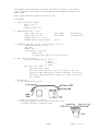
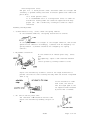
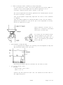
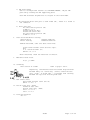
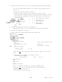
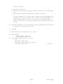
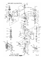
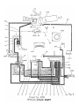
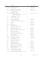
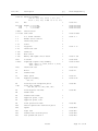
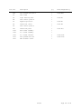
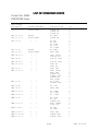
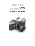
PRODUCT No. 23903
SERVICE MANUAL
ENGLISH
Disassembling and assembling procedures are almost the same as 23900 and/or
23901. Therefore, the details of disassembling and assembling procedures are
abbreviated.
Here is explained about special items for 23903.
Disassembly
1. Bottom cover assy. (A400)
CSS 1.7 x 3 x 2
CSS 1.7 x 2
Connector seat (A23)
2. Winding lever assy. (0-C69)
Cover screw (C139-01)
Winding lever nut (C8)
Winding lever assy, (0-C69)
Winding lever friction spring
left handed
left handed
23600K-C135-A
23600K-C134-A-2
(C7-01)
3. Rewinding knob assy. (0-D6), ASA ring assy. (D-D11-01)
Rewinding knob assy. (0-D6)
Nut (D15)
*Washer (D21)
ASA ring assy. (0-D11-01)
*Washer (D2l)
To adjust the torque of click of ASA ring.
4. Top cover assy. (A300)
Top cover retainer screw A (A333) x 2
B (A334)
C (A342) x 2
D (A345)
*Top cover assy. (A300)
*Top cover assy. (A300)
Material of Top cover assy. (A300) is a plastic. But the
surface is made conductive by surface treatment. So that the
electrical conductive does not apply on the back of Top cover
assy. (A300).
5. Unsoldering
1) P.C. board pattern (T100)
2) Relay P.C. board assy. (0-A129)
Before unsoldering, take out Insulation seal (A152)
to prevent melting by soldering iron.
23903
Page 1 of 32
3) f-volume (K101)
4) Hot shoe contact A (N4), Hot shoe contact C (N9)
5) EF switch contact piece (A44)
Before unsoldering, take out ASA volume (R100)
ASA volume retainer screw (A16-01)
CNL-D 1.7 x 2. 5
ASA volume (R100)
6) Connector base plate assy. (0-A21)
6. Self-timer charge lever assy. (0-A118)
Self-timer screw (A122)
Self-timer charge lever assy. (0-A118)
Self-timer collar (A123)
W30
231K-H50
7. Body covering
Body covering, right (A19)
Body covering, left (A20)
After peel off, re-install Self-timer charge lever assy. (0-A118)
8. Front board and Mirror housing complete assy.
At the charged condition.
CNL-D 1.7 x 3 x 2
P.C. board pattern retainer (I1)
W14
Front board retainer screw (A132-01) x 4
9. P.C. board pattern (T100)
T-CNL-E 1.7 x 4
Hot shoe contact piece A (N4)
Insulation collar (N8)
Insulation plate (N13)
T-CNL-E l.7 x 3
Hot shoe contact piece C (N9)
CNL-D 1.4 x 3
LED retainer collar (T212)
23903
Page 2 of 32
*PC board pattern (T100)
LED part in P. C. board pattern (T100) should be taken out straight and
carefully to prevent making scratches on Shutter speed scale indication
plate (M10).
*P.C. board pattern (T100)
It is recommended that P.C. board pattern (T100) is taken out
from Mirror housing under the condition separated from Body
proper (A1). due to difficulty of LED part taken out and/or
installed.
Assembly and Adjustment
1. Cocked indicator assy. (0-C23) Check the spring tenSion.
At the released condition, the spring should have no tension.
If the spring tension is stronger at the charged condition, 2nd curtain
speed will be affected. Accordingly, 1/2000sec will be changed by its
spring tension. (l/2000sec should be not changed by its spring
tension.)
2. Adjustment of Main SW
At the condition of release plate assy. (A500)
goes
up completely, adjust 0.5mm clearance between
the
contact pieces by turning eccentric screw.
Adjust the clearance by eccentric screw in the range shown below to
prevent the side of screw touching the body when the shutter rod pushed
down or up.
If the clearance is wider
than 0.5mm, the shutter
will be stayed open at the
1st exposure when released
by Self-timer or Winder.
3. EF- switch contact piece (A44)
The clearance of A should be within 0.3mm.
Adjust the clearance by bending the part of
B.
23903
Page 3 of 32
4. Bulb off adjustment
Install *the temporary top cover and set the shutter dial Bulb.
Within the range A, 2nd curtain
should be released. Adjust by
eccentric screw.
Confirmation
1) Change the shutter dial 125X. And release the shutter. The shutter
speed should be1/125 sec, not 1/500 or l/l000sec.
2) At the charged condition, release only the shutter block, not push
the shutter button. The shutter speed should be 1/125 sec, not 1/500
or l/l000sec.
*The temporary top cover
5. Dumper lever plate assy. (0-B90)
Adjust the actuating torque by turning Nut (B96).
About 1.5 teeth out from the surface of nut (B96).
The level of actuating torque is depends on the
greatness of mirror bounce.
Confirmation
1) When drop the mirror seat from up-position,
an afterimage of dumper lever plate down and up
can be seen after the mirror seat hitted with
the dumper lever plate.
2) When pushed down the dumper lever plate, and returned slowly, the
dumper lever plate should be returned to the original position
completely by its own tention. If not, check *Friction washer (B94).
*Friction washer (B94)
Material:
Calfskin
a. It is prohibited to apply any grease in order to the
material of friction washer (B94) is calfskin.
b. When install, fluffy surface should be faced up.
23903
Page 4 of 32
5. Check of Shutter block (0-E000) by using T-adjuster
It is prohibited to adjust the curtain speed and the shutter speed in
0-E000. If the curtain speed and the shutter speed was out of
tolerance, replace Shutter block (0-E000) to new one.
The curtain speed and the shutter speed must be checked before install
the mirror housing to the body.
*The curtain speed is especially important for 23903 so that l/2000sec.
is adopted.
*The auto-manual speeds are already decided on T100. The auto-manual
speeds which decided on T 100 can not get if the adjustment of timing
switch in 0-E000 was no good.
Insert Connector (23900-I 100) to
Adapter for T-adjuster. Distribute
lead wires as shown left.
To actuate the auto-manual hutter,
install temporary top cover and
set the shutter dial AUTO or M, or
insert 2 mm diameters pin between
C14-01 and C24.
6. Time-sequence of SWg and SWm
It is requested that Adapter for checking the time-sequence of SWg and
SWm should be made by your own side.
Adjusting procedures and the tolerance are the same as 23900.
7.
P.C. board pattern (T100)
1) LED part
LED retainer collar (T212)
CNL-D 1.4 x 2.5
Confirm that LED insulation seal (I18) was sealed on the back side of
LED supporting plate.
23903
Page 5 of 32
2) LED positioning
Use P.C. board pattern checker (239 PATTERN CHECKER). Adjust LED
position by sliding the LED supporting plate.
Each LED should be aligned with its figure in the view-finder.
3) As installing Photo-cell part to Cell frame (N1), insert P.C. board to
the connector.
4) Photo-cell part
Hot shoe contact piece C (N9)
T-CNL-E 1.7 x 3
Insulation plate (Nl3)
Insulation collar (N8)
Hot shoe contact piece A (N4)
T-CNL-E 1.7 x 4
8.
Front board and Mirror housing
Shutter block
charged condition
Mirror housing
released condition
*lAThen installed, take care about lead wires.
Front board retainer screw (A132-01) 4pcs.
W14
P. C. board retainer (I1)
CNL-Dl.7 x 3 x 2
After installed, check the functions of shutter.
9.
Mechanical back focus.
45,46 ± 0.04mm
10. Soldering
The location of solder
refer to page 1 and 2.
Especially, red and blue lead wire should be positioned
between Relay P.C. board assy. (0-A129) and Prism seat
assy. (0-M2), as shown left. — to prevent from catching
between the top cover and the prism seat.
11. ASA volume (R100)
ASA volume retainer scerw (A16-01)
CNL-D 1.7 x 2. 5
12. Bottom cover assy. (A400)
Connector seat (A23)
Bottom cover assy. (A400)
CSS 1.7 x 3 x 2
CSS 1.7 x 2.2
13. Load the batteries
G13 x 2
23903
Page 6 of 32
14.
Confirm the function of LED of P.C. board pattern and/or LED positioning
*If P.C. board pattern checker is not ready, adjust LED position at
this time.
Confirm the function of LED as follows.
1) After the main switch was ON, LED stays on about 30 sec..
2) LED indicates as Manual-mode at when the top cover does not install.
3) LED should be changed the indication when connect the points as
mentioned below.
a.
A — D Auto-mode CBA D =ground
b.
B — D
Manual-mode
LED keeps down
c.
C — D
Manual-mode
LED keeps up
15.
Install ASA ring assy. (0-D11-01) temporary.
When set ASA ring out of 1X, red LED of EE should be flickering.
16.
Install the temporary top cover.
17.
Adjust the auto shutter-speed and the LED indication.
1) Auto shutter-speed
EV12
ASA100 1X
f8 — using f8 set ring
2.8V
supply
Shutter dial AUTO
*Nominal speed
Light value correction unit
KA-00- 1A
Regulated D. C. power
15.6 ms
Adjust by VR1. After adjusted, check other EVs. (EV16 1X, EV16 1/2X,
EV8)
Standard of shutter speed is the same as 23900.
*Standard of 1/2000sec.
0.49±0.7EV ms.
(0.30
0.81 ms.)
2)
LED indication
EV12
ASA 100 lX
f8
2.8V
Shutter dial AUTO
LED of 60 should be turned on at the above combinations.
Adjust by VR2. LED of 60 should not move to next LED when
changed ASA from 80 to 125.
After adjusted, check other EVs.
23903
Page 7 of 32
3) Auto manual-speed and the indication
Shutter dial M
Shutter speed tester (7F-9A-
a. Check the curtain speed at 1/l000sec.. 6.5ms or faster at 21mm
distance
b. Check each shutter speed from 1/2000 sec. ~ 4 sec..
c. Each LED should be turned on when changed the shutter speed, and
OVER or UNDER LED must be flickering when non-proper exposure was
made.
*As a general rule, use Light value correction unit and Shutter speed
tester (7F-9A-2) for checking and/or adjusting the shutter speed and the
indication. However, Shutter speed tester (7PE-25A3) may use by the
circumstances.
4) LED indication and Shutter speed under the full-charged condition of AF2OOS or AF-160
When load 2.4V between the ground and Hot shoe contact piece A (N4), LED
indication and the shutter speed are as below.
a. LED indication
M — flickering
125X — on
b. Shutter speed
9.6 -— 11.8ms
5)
Battery check
2.4V
LED off or flickering
2.65V
LED on
18.
Remove ASA ring and the temporary top cover
19.
Clean the view-finder
*Do not use the air-compressed blower to clean the view-finder. It will
be caused by taking out Shutter speed indication plate (M10).
20.
Top cover assy. (A300)
Check the conductivity of Switch board (A318) before install Top cover
assy. (A300).
a. At Shutter dial AUTO
A — the ground
B
C
OFF
— the ground
OFF
a. At Shutter dial M
A — the ground
B
C
ON
— the ground
— the ground
OFF
OFF
— the ground
OFF
When pushed the bottom side button,
ON
B — the ground
When pushed the up side button,
ON
C — the ground
23903
Page 8 of 32
If the conductivity of Switch board (A318) was good, install Top cover
assy. (A300).
The point of installation is the same as 23900 ME.
Cover frame (A131)
Top cover retainer
Top cover retainer
Top cover retainer
Top cover retainer
screw
screw
screw
screw
A
B
C
D
(A333)
(A334)
(A332)
(A335)
2pcs.
2pcs.
After installed, check the function of LED by changing the shutter
dial.
21.
ASA ring assy. (0-D11-01), Rewinding knob assy. (0-D6)
ASA ring assy. (0-D11-01)
Washer (D21)
Nut (D15)
After installed, check the function of click of ASA ring assy. (0-D1101). and the LED indication.
At 1/4X, 1/2X, 2X and 4X except 1X, EF red LED must be flickering. If
not, check the clearance of ElF switch contact piece (A44) and lead
wires and/or adjust ElF index plate (D23) assembled in ASA ring assy.
(0-D11-01), as shown below.
0-D11-01
D23
Fix D23 as pushing to the
arrowed
direction
Rewinding knob assy. (0-D6)
22.
Winding lever assy. (0-C69)
Winding lever friction spring (C7-01)
Winding lever assy. (O-C69)
Winding lever nut (C8)
left handed
Cover screw (C139-01)
left handed
23600K0C134-A-2
23600K-C135-A
Check the function of shutter and winding.
23.
Check the shutter button stroke Shutter dial Bulb
a.
b.
When pushed the shutter button deeper than 0. 2mm from the original
position, LED should be turned ON before release the shutter.
Main switch ON position
After released 1st curtain, the shutter button can goes down
0. 1 - 0.5mm.
23903
Page 9 of 32
Shutter dial AUTO
a. Charge the self-timer.
b. Release the shutter by self-timer under main switch off. (No LED turned
on.)
c. LED should be turned on surely before release the shutter.
If LED is turned on at the same time or after the shutter released, the
shutter by actuating with self-timer or winder will be AUTO-TIME at 1st
exposure under main switch off. In this case, the clearance of main
switch is wider than 0. 5mm. The clearance should be adjusted less than
0. 5mm.
24. Check the conductivity of Hot shoe and the full-charged indication Checking
procedures are the same as 23901 MV.
25. Focusing
26. Remove Self-timer charge lever assy. (0-A118)
27. Body covering
Body covering, left (A19)
Body covering, right (A20)
28. Self-tirner charge lever assy. (0-A118)
W30
Self-timer collar (A123)
Self-timer charge lever assy. (0-A118)
Self-timer screw (A 122)
23903
231K-H50
Page 10 of
32
Special Tools
23903k-B95-A
23903K-B96-A
23903
Page 11 of
32
239 PATTERN CHECKER
Body
LED — to indicate shutter speed Switches
A-M — Auto-manual switch (for 23903)
UP-DOWN
UP-DOWN switch for manual
speed (for 23903)
*LED goes down when set DOWN position.
*LED goes up when set UP position.
EF —EF switch (for 23903)
*When set ON position, red LED at the top
flickering.
SWT — Timing switch
SWM/SWG — Memory and Magnet switch
Power switch
*If use G13 x 2, power switch is ON when set
BATT ON.
*If use exterior power- sorce, power switch is
ON when set EXT ON.
Adapter
23903
Page 12 of
32
How to use
1. Preparation
a. If use two batteries (G13 x 2), load them to battery case.
b. If use exterior power sorce, connect the body and the exterior power
sorce with connection cord. And set the voltage 2. SV.
2. Check 23900 P.C. board pattern
a. Install the adapter for ME to the connector.
b. Set Power switch OFF and insert P.C. board pattern to the connector of
adapter.
c. Set ME-MV switch to ME side
d. Set Timing switch ON.
e. Set Memory switch ON.
Check the LED function
a. Power switch ON. At this time, check LED lights on.
b. Turn VR-dial and check each LED light on or not. If LEDs in slow speed
side does not light on even if VR-dial turned fully, cover up the photosenser part step by step.
Check the shutter function
*Shutter speed indicated with LED in P.C. board pattern can be checked by
the lighting time of LED of checker body.
a. Set a shutter speed by turning VR-dial. Slower speed is better to check.
To get accurate shutter speed, it need to give constant light on the
phot-senser part.
b. Set Timing switch OFF.
c. Set Memory switch OFF.
At this time, LED of checker body lights on for the time indicated on P.
C. board pattern.
d. Repeat the above mentioned process. And check the shutter speed constant
or irregular.
*Due to difficulty to confirm the accurate and/or irregular shutter
speed, shutter speed checked by LED of checker body is judged a criterion
for the time being.
3. Check 23903 P.C. board pattern
a. Install the adapter for ME-super to the connector.
b. Set ME-MV switch to ME side.
c. Insert P. C. board pattern to the connector of adapter.
d. Check the function and indication of auto-mode.
23903
Page 13 of
32
Check the function and indication of auto-mode
a. Set A-M switch to A-side.
b. Checking process is the same as ME mentioned before.
Check the function and indication of manual-mode
a. Set A-M switch to M-side.
b. Set UP-DOWN switch OFF position.
c. Confirm LED movement.
*LED should moves up and/or down to the direction which fixed by UP-DOWN
switch.
Check the indication of EF
Red LED at the top should be flickering when set EF switch ON.
4. Check 23901 and 23904 P.C. board pattern
a. Install the adapter for MV to the connector.
b. Set ME-MV switch to MV side.
c. Insert P.C. board pattern to the connector of adapter.
d. Checking process is the same as ME. But the application range of VR is
opposite.
23903
Page 14 of
32
Product No. 23903
PENTAX ME Super
Note:
LIST OF SERVICE PARTS
1: The parts with numbers starting '0-' are assemblies
2: Only available parts are listed below.
Parts No.
Description
Qty
Interchangeability
A2
Back cover key
1
23900-A2
A3
Back cover key collar
2
23900-A3
A4
Back cover key retainer plate
1
23900-A4
A5
Back cover guide screw
1
23900-A5
0-A6
Strap hook assembly
(A6, A18)
2
23900-0-A6
A8
Shutter light seal cover
1
23900-A8
A9
Cassette receptacle
1
23900-A9
A10
Back cover shaft receptacle
1
23900-Al0
0-A11
Battery case assembly
(A11, A12, A14)
1
23900-0-A11
A13
Tripod seat
1
23900-A13
A15
Back cover key retainer spring
1
23901-A15
A16-01
ASA volume retainer screw
1
23901-A16-02
A19
Body covering, left
1
23900-A19
A20
Body covering, right
1
23900-A20
0-A21
Connector base plate assembly
(A21, A22, A24 x 3)
l
23900-0-A21
A23
Connector seat
1
23900-A23
A25
Connector retainer screw
1
23900-A25
A26
Light seal D
3
23900-A26
A28
Light seal F
2
23900-A28
A30
Light seal
1
23900-A30
A31
Light seal A
1
23900-A31
A32
Light seal B
1
23900-A32
A33
Light seal C
1
23900-A33
A34
Light seal tape
1
23900-A34
A35
Light seal
1
23900-A35
A36
Light seal
2
23900-A35
A37
Light seal
2
23900-A37
A38
Light seal J
1
23900-A38
0-A39
Exposure-compensation selector seat assy
(A39, A40, A41)
1
A42
Click spring
1
23903
Page 19 of 32
Parts No.
Description
Qty
A43
EF switch contact piece installing seat
1
A44
EF switch contact piece
1
A45
EF switch contact piece insulation washer
l
A46
Stopper
1
A100
Front board assembly
(A101, A102, A104, A105, A106 x 6,
A107, A108, A109, A110, A117, A121 x 2,
A124, A125, A126, A127, A128, A129,
A133, A134 x 2, A135, A136, A137, A138,
A139 x 3, A151 x 4, K101, K102, K103 x 2,
K104, K105 x 2, K106, K107, K108 x 2,
K109, CNS 1.7 x 2 x 2, CNS 1.7 x 2.5 x 4,
CNS 2 x 2.5 x 2)
1
A104
Mount ring
1
23900-A104
A105
Mount spring
1
23900-A105
A106
Mount retainer screw
6
23900-A106
0-A107
Mount lock button assembly
(A107, A108, A109)
1
23900-0-A107
A110
Mount lock button spring
1
23900-A110
0-A111
Mirror release lever assembly
(A111, A112, A113, A114, A115, A116)
1
23900-0-A111
A114
Coupler lever spring
1
23900-A114
0-A118
Self-timer charge lever assembly
(A118, A119)
1
23900-0-A118
A120-01
Charge cam
1
23900-A120-Ol
A122
Self-timer screw
1
23900-A122
A123
Self-timer collar
1
23900-A123
0-A126
Synchro terminal assembly
(A126, A124, A125)
1
23900-0-A126
A127
X contact relay plate
1
23900-A127
0-A129
Relay P. C. board
(A129, A117, A121 x 2, A138, A139 x 3,
A151 x 4)
1
A130
Light seal plate
1
23900-A130
A131
Cover frame
1
23900-A131
A132-01
Front board retainer screw
4
23900-A132-01
A133
Lock pin supporter plate
1
23900-A133
A134
Diaphragm coupler ring retainer
2
23900-A134
A135
Restitution spring
1
23900-A135
A136
Light seal
1
23900-A136
A137
Scratch protection seal
1
23900-A137
A152
Insulation seal
1
A200-02
Back cover assembly
(A20 1-02, A202, A203, A207, A208 x 2,
A209 x 2, A210, A211, A212, A213,
A214-02, A219-02, A222-01 x 4,
A230 x 2)
1
23903
Interchangeability
23900-A200-02
Page 20 of 32
Parts No.
Description
Qty
Interchangeability
0-A204
Pressure plate assembly
(A204, A205, A206 x 2)
1
23900-0-A204
A220
Pressure plate cover
1
23900-A220
A230
Light seal
2
23900-A230
A300
Top cover assembly
(A301, A303, A304, A305, A307, A 11,
A312, A313, A314, A315, A316, A317,
A318, A319, A320 x 2, A321, A322,
A323, A324, A325, A326, A327, A328,
A329, A330, A331, A332, A335, A336,
A337, A338, A339, A340 x 2, A341,
A343, A344, A347 x 4, D20,
CSS 1.7 x 4 x 4, T-CNS 1.7 x 3,
T-CSS 1.7 x 2.5 x 3, T-CNM 1.7 x 4)
1
A303
Click pin
1
A304
Click pin spring
1
A305
Bearing
1
0-A307
Click plate assembly
(A307, A311)
1
A312
Auto-manual selector plate
1
A313
Release button, bottom
1
0-A314
Shutter buton assembly
(A314, A341)
1
A315
Shutter button core
1
A316
Shutter dial
1
23900-A304
23901-0-A314
A317
Release button
1
A318
Switchboard
1
A319
Switch board insulation sheet
1
A320
Control button
2
A321
Switch spring
1
A322
Accessory shoe
1
A323
Accessory shoe spring
1
0-A324
Accessory shoe base assembly
(A324, A325, A344)
1
A326
Contact spring A
1
A327
Contact spring B
1
A328-01
Collar
1
23900-A328-01
A329
Retainer screw
1
23900-A329
A330-01
Insulation washer
1
23900-A330-01
A331
SW pin
1
23900-A331
A332
Indication plate
1
23900-A332
A333
Top cover retainer screw A
2
23602-A342-01
A334
Top cover retainer screw B
2
A335
Shutter indicator plate
1
23903
23900-A317
Page 21 of 32
Parts No.
A336
Description
Qty
Interchangeability
Window A
1
23900-A336
A337
"
B
1
23900-A337
A338
"
C
1
23900-A338
Insulation tape
1
23900-A339
2
23900-A340
A339
A340
A342
Top cover retainer screw C
2
A343
Shutter button retainer washer
1
A345
Top cover retainer screw D
1
A346
Nut
1
A347
Accessory shoe retainer nut
4
A400
Bottom cover assembly
(A401, A402, A408, C209)
1
23900-A400
A403
Bottom winding cap
1
23900-A403
A405
Battery cap
1
23900-A405
A408
Scratch protection seal
1
23900-A408
A500
Release plate assembly
(A501, A502, A503, A505, A506, A509,
A512, A513, A514, CNS 1.4 x 5)
1
A504
Bulb actuator plate
1
23900-A504
A507
Guide screw
1
23900-A507
A508
Spring hook B
1
23900-A508
A510
Release plate restitution spring
1
23900-A510
A511
Connection spring
1
23900-A511
0-A513
SW adjusting plate assembly
(A513, A512)
1
0-B000
Mirror housing complete assembly
1
(B1, B2, B3, B4, B5, B6, B7, B8, B9,
B11, B12, B13, B14, B15, B1G, B17,
B18, B19, B20, B21, B22 x 2, B23,
B24, B25, B26, B27, B28, B30, B31,
B32, B33, B34, B35, B36, B37, B38,
B39, B40, B41, B42, B43, B44, B45,
B51 x 2, B52 x 3, B53, B54, B55, B57,
B60 x 2, B61, B62, B63, B70, B71, B81,
B82, B83, B84, B85, B86 x 2, B90, B91,
B92, B93, B94, B95, B96, B97, B98,
B101, B102, B103, B105, B106, B107,
B108, B109, B111, B112, B201, B202,
B203, B204, B205 x 4, B206, B207,
B208, B210, B211, B215, B216 x 3,
B217, B218, I8, I9, I10, I19, I300,
L1, M6, M7, CSS 1.7 x 2.2 x 6,
CSS 1.7 x 2.5 x 2, CNS 1.7 x 2,
CNS 1.7 x 2.5 x 3, CNM 1.7 x 3,
CNL-D 1.4 x 3. 5, CNL-F 1.7 x 2.5, W2,
W3, W27, W31, W36, W70, W78, W88, W89,
LW10, LW13, LW17 x 3, LW20)
B4
Supporter plate, right
1
23900-B4
B5
Supporter plate, left
1
23900-B5
23903
23901-A343
Page 22 of 32
Parts No.
Description
Qty
Interchangeability
0-B7
Hook lever B assembly
(B7, B6, B9, B86 x 2)
1
0—B11
Mirror actuator lever assembly
(B11, B51, B210)
1
0-B12
Diaphragm coupler lever assembly
(B12, B13, B15, B51, B81, B82, B83,
B84, B208, W88)
1
0—B16
Restitution link A assembly
(B16, B19, B36)
1
23900-0-B16
B17
Slide shaft nut
1
23900-B17
B18
Restitution link slide shaft
1
23900-B18
B20
Restitution link B shaft
1
2390Q-B20
B22
Spring hook
2
B23
Release lever shaft
1
23900-B23
B24
Release lever
1
23900-B24
0-B25
Restitution actuator lever hook plate assy. 1
(B25, B26)
23900-0-B25
B27
Restitution actuator lever hook plate
shaft
1
23900-B27
B28
Mirror up lever
1
23900-B28
0-B30
Restitution actuator lever assembly
(B30, B31, B33, B44, B211)
1
0-B34
Shock absorber connection lever assembly.
(B34, B35, B39, B57)
1
B38
Shock absorber lever
1
0-B40
Shock absorber assembly
(B40, B41, B42, B45)
1
B43
Restitution spring hook screw
1
23900-B43
B51-00A
Mirror actuator collar a
2
23900-B51-00A
23900-B38
-00B
"
"
"
b
23900-851-00B
-00C
"
"
"
c
23900-851-00C
-00D
"
"
"
d
23900-851-00D
B32-00A
-00B
-00C
-00D
-00E
Shock absorber collar a
"
"
"
b
"
"
"
c
"
"
"
d
"
"
"
e
3
B54
Shock absorber lever shaft
1
23900-B54
0-B55
Mirror seat assembly
(B55, B2, B3, B201, B202, B203, B204,
B205 x 4, B206, LW10)
1
23900-0-B55
B60
Light seal
2
23900-B50
B61
Light seal A
1
23900-B61
B62
Light seal B
1
23900-B62
B63
Light seal C
2
23900-B63
B71
Spring washer
1
23900-B71
23903
Page 23 of 32
Parts No.
Description
Qty
0-B90
Dumper plate assembly
(B90, B91)
1
B92
Dumper plate shaft
1
B93
Connection lever
1
B94
Friction washer
1
B95
Connection lever shaft
1
B96
Nut
1
0-B98
Mirror seat adjusting plate assembly
(B98, B97)
1
B101
Mirror seat restitution spring
1
23900-B101
B102
Diaphragm actuator lever spring
1
23900-B102
B103
Diaphragm actuator spring
1
B105
Hook lever restitution spring
1
B106
Restitution actuator lever hook plate
spring
1
23900-B106
B107-01
Release lever restitution spring
1
23900-B107-01
B108-01
Mirror flip-up spring
1
B109
Mirror restitution spring
1
B111
Shock absorber lever spring
1
B112
Connection lever spring
1
B201-01
Light seal curtain
1
23900-B201-01
B203
Collar
1
23900-B203
B207
Washer
1
23900-B207
B215
Mirror adhesive tape
1
23900-B215
B216
Focus adjusting screw
3
23900-B216
B217
Light seal
1
23900-B217
B218
Dust prevention seal
1
23900-B218
B220
Light seal
1
23900-B220
0-C1
Top mech. plate assembly
(C1, C13, C20, C27, C28, C29, C31,
C32, C33, C37, C43, C44, C46, C60,
C63, C64, C66, C142-01,
CNL-F l.7 x 2.5, W13, W75)
1
23900-0-C1
0-C2-02
Winding seat assembly
1
(C2-02, C4-01, C6, C14, C16-01, C17,
C18-01, C21, C24, C39, C47, C50-02,
C51, C52, C59, C61, C71-01, C76, C78,
I200, CNS 1.4 x 2, CNS 1.4 x 4.5,
CNM 1.4 x 1.4, W6, W89, LW13 x 2)
C5-01
Winding lever click cam
1
23901-C5-01
C7-0l
Winding lever friction spring
1
23900-C7-01
C8
Winding lever nut
1
23900-C8
0-C12
Winding spring assembly
(C12, C137, C138)
1
23900-0-C12
C14
Switch actuating lever
1
23903
Interchangeability
Page 24 of 32
Parts No.
Description
Qty
Interchangeability
C15-01
Counter dial indicator
1
23901-C15-01
C16-01
Receiving claw
1
23901-C16-01
C17
Winding lever click spring
1
23900-C17
0-C18-01
Transporting claw assembly
(C18-01, C47)
1
23900-0-C18-01
C21
Release lock lever
1
0-C22-01
Winding shaft assembly
(C22-0l, C48 x 2, C67 x 2, C68, C140,
C141-01, C154, C201)
1
0-C23
Cocked indicator assembly
(C23, C74)
1
C24
Shutter control lever
1
C25
Counter retainer plate
1
23900-C25
0—C26
Winding stopper assembly
(C26, C41-01, C42, C65, C77, LW10)
1
23901-0-C26
C30
Main gear
1
23900-C30
C31
2nd gear
1
23900-C31
C34-01
Counter dial
1
23901-C34-0l
C40
Sprocket shaft pin
1
23900-C40
C49
Cocked indicator lever shaft
1
C51
Restriction lever shaft
1
23900-C51
C53
Winding seat retainer screw
1
23900-C53
C54
Counter dial indicator retainer screw
1
23901-C54
C57
Counter dial spring
1
23900-C57
C59
Release lock lever spring
1
23900-C59
Shutter restriction lever spring
1
23900-C61
C63
Cam lever spring
1
23900-C63
C54
Silent ratchet spring
1
23900-C64
C65-01
Transporting claw spring
1
23901-C65-C1
0-C69
Winding lever assembly
(C69, C70)
1
23900-0-C69
C71-01
Release lock lever shaft
1
C72
Winding shaft retainer
1
23900-C72
C73
Transporting marker
1
23900-C73
C75
Cocked indication marker
1
23900-C75
C78
Counter dial indicator stopper
1
23901-C78
C79
Winding lever click spring
1
23900-C79
C80
Winding stopper retainer screw
1
23900-C80
C81
Strap hook retainer
1
23900-C81
0-C101
Bottom mech. plate assembly
(C101, C110, C118, C120)
1
23900-0-C101
0-C102
Winding guide plate assembly
(C102, C103, C104, C112, C113, C114)
1
23900-0-C102
23903
23900-0-C22-0101
Page 25 of 32
Parts No.
Description
Qty
Interchangeability
0-C105
R lever assembly
(C105, C119)
1
23900-0-C105
0-C106
Winding lever ratchet wheel assembly
(C106, C121, C122, C128)
1
23900-0-C106
C107
Winding lever ratchet
1
23900-C107
C108
Winding hook lever
I
23900-C108
0-C109
Sprocket shaft assembly
(C109, C134, C135, C136)
1
23900-0-C109
C111
Spring hook screw
1
23900-C111
C116
Sprocket seat
1
23900-C116
C117
R button
1
23900-C117
C124
Winding hook coupler spring
1
23900-C124
C125
Hook lever spring
1
23900-C125
C126
R lever spring
1
23900-C126
C127
Mirror charge lever spring
1
23900-C127
0-C129
Shutter charge lever assembly
(C129, C115, C123)
1
23900-0-C129
C130
Winding ratchet collar
1
23900-C130
C131
Sprocket collar
1
23900-C131
C132
Sprocket
1
23900-C132
C133
Sprocket spring
1
23900-C133
C139-01
Cover screw
1
23900-C139-01
C141-01
Winding ratchet spring
1
23900-C141-01
C144
Shutter charge collar
1
23900-C144
C145
Winding ratchet spring
1
23900-C145
C146
Seat plate retainer screw
5
23900-C146
0-C147
Bottom release assembly
(C147, C148, C149, C150, C151, C152,
C153)
1
23900-0-C147
C202-01
Spool cam
1
23900-C202-01
C203
Friction ring
1
23900-C203
0-C204
Spool assembly
(C204, C205 x 14, C206, C208)
1
23900-0-C204
C207
Joint
1
23900-C207
C210
Spool cam receptacle
1
23900-C210
C211
Light seal washer
1
23900-C211
0-D6
Rewind knob assembly
(D6, Dl, D2, D3, D4, D5,
CNM 1.4 x 2 x 2)
1
23900-0-D6
D7
Rewinding shaft
1
23900-D7
D8
Rewinding shaft spring
1
23900-D8
0-D10
Rewinding shaft bearing assembly
(D10, D8, D9)
1
23900-0-D10
23903
Page 26 of 32
Parts No.
Description
Qty
Interchangeability
O-D11-01
ASA dial assembly
1
(D11-01, D12, D13, D14 x 3, D16, D17,
D18 x 3, D19, D23, T-CNS 1.4 x 2.5 x 2)
D15
Nut
1
23900-D15
D21-00A
-00B
-00C
Washer a (t=0.1mm)
"
b (t=0.15mm)
"
c (t=0.2mm)
1
23900-D21-00A
23900-D21-00B
23900-D21-00C
0-E000
Shutter block
1
0-1-1000
Self-timer
1
23900-0-K000
I 1
P.C. board retainer
1
23901-I 1
I 8
Winder switch contact
1
I 9
Insulation plate
1
I 10
Collar
2
I 19
Lug plate
1
I 20
Insulation seal
1
I 100
Connector
I 200
Main switch
1
I 300
Memory and magnet switch block
1
23900-I 300
K101
f-volume
1
23900-K101
0-K102
Diaphragm coupler ring assembly
1
(K102, K103 x 2, K104, K105 x 2, K106,
K107, K108 x 2)
23900-0-K102
K109
Insulation seat
1
23900-K109
L1
Mirror
1
23900-L1
L2
Fresnel lens
1
L3
Penta prism
1
23900-L3
0-L4
Eyepiece assembly
I
23900-0-L4
23900-M1
23901-I 19
(L4, L5)
M1
Focusing screw receptacle plate
1
0-M2
Prism seat assembly
(M2, M4, M9 x 2, M10, M14, M16)
1
M3
Focusing plate retainer
1
M4
Finder mask
M5
Fresnel lens frame
1
M6
Supporter plate, right
1
M7
Supporter plate, left
M8
Prism protection sheet
2
M10
Shutter speed scale indication plate
1
M14
Spacer
1
23900-M14
M16
Light seal
1
23900-M16
M18
Fresnel lens retainer plate
1
23900-MI8
M19
Dust prevention seal A
1
23900-M19
23903
23900-M3
23900-M8
Page 27 of 32
Parts No.
Description
Qty
Interchangeability
M20
Dust prevention seal B
1
23900-M20
N1
Cell frame
1
N3
Light metering lens
2
N4
Shoe contact piece A
1
N7
Eyepiece protector
1
23900-N7
N8
Insulation collar
1
23901-N8
N9
Shoe contact piece C
1
N13
Insulation plate
1
R100
ASA volume assembly
1
T100
P.C. board assembly
1
T108
P.C. board retainer
2
23900-T108
T210
Dust prevention seal
1
23900-T210
T212
LED retainer collar
1
23903
23900-N3
23901-N13
Page 28 of 32
LIST OF STANDARD PARTS
Product No. 23903
PENTAX ME Super
Small Screws:
Description
Surface Treatment
Position of Use
Qty
CSS 1.7 x 2.2
Black nickel
0-B000, B5
0-B000, M6
0-B000, M7
2
2
2
CSS 1.7 x 2.2
Nickel
A1, A400
1
CSS 1.7 x 2.5
Black nickel
0-B000, B4
2
A1,
A1,
A1,
A1,
A1,
2
2
2
1
1
CSS 1.7 x 3
"
"
A4
A10
0-A39
0-C1
0-C102
CSS 1.7 x 3
Nickel
A1, A400
2
CSS 1.7 x 4
Black nickel
A300, A322
4
CNS 1.4 x 1.5
"
"
A500, Q-A513
0-C2-02, C17
1
1
CNS 1.4 x 2
"
"
0-C2-02, I200
1
CNS 1.4 x 4.5
"
"
0-C2-02, I200
1
CNS 1.7 x 1.8
"
"
0-M2, M6
0-M2, M7
1
1
CNS 1.7 x 2
"
"
A100, K101
2
CNS 1.7 x 2.5
"
"
A100, 0-A129
A100, A133
0-B000, I10
0-B000, 0-M2
0-B000, M6
C40, 0-C109
2
2
2
2
1
1
CNS 1.7 x 3
"
"
A1, 0-C102
0-B000, 0-B98
1
1
CNS 1.7 x5
"
"
A1, 0-A6
1
CNS 2 x 2.5
"
"
A100, A134
2
CNM 1.7 x 2.2
"
"
A1, 0-A21
A1, 0-C147
1
1
CNM 1.7 x 2.8
"
"
A1, 0-C147
1
CNM 1.7 x 3
"
"
A1, 0-A11
A1, A13
0-B000, B71
2
2
1
CNM 1.7 x 3.5
"
"
A100, 0-H000
0-C26, C72
2
1
CNL-D 1.4x 2
"
"
A1, A45
A1, A504
1
1
CNL-D 1.4 x 3
"
"
T100, T212
1
CNL-D 1.4 x 3.5
"
"
0-B000, B207
1
CNL-D 1.7 x 2
"
"
0-B000, 1100
1
23903
Page 29 of 32
Description
Surface Treatment
Position of Use
Qty
CNL-D 1.7 x 2.5
Black nickel
Al, 0-C2-02
Al, R100
1
1
A1,
A1,
A1,
N1,
N1,
I 1
M6
0-E000
M6
M7
1
1
2
1
1
CNL-D 1.7 x 3
"
"
CNL-D 1.7 x 3
Black zinc
A1, 0-E000
1
CNL-F 1.7 x 2.5
Black nickel
0-B000, B24
0-C1, C31
1
1
T-CSS 1.7 x 2.5
"
"
0-A307, A316
3
T-CNS 1.7 x 3
"
"
A1, A335
N1
1
1
T-CNM 1.7 x 4
"
"
A300, A321
1
T-CNL-E 1.7 x 3
"
"
N1, N9
1
T-CNL-E 1.7 x 4
"
"
N1, N8
1
Set T 1.7 x 4
"
"
0-M2
2
Washers:
Description
Material
Thickness
Position of Use
Qty
W2
Brass
0.5mm
0-B000, B4
1
W3
Delrin
0.3
0-A129
1
W3
Brass
0.3
0.5
0.5
A1, 0-A139
0-A126, A127
B38, 0-B40
1
1
1
W6
"
0.03, 0.05, 0.1
0.1, 0.15
0.2
A100, A134
C16-01
0-C26
2
1
1
W8
"
0.08, 0.1, 0.15
A500, A507
1
W13
"
0.1
0-C1
1
W14
"
0.1, 0.15
0.1, 0.2, 0.3, 0.4
0.1, 0.2, 0.3, 0.4
0.1
0.05, 0.1, 0.15
A1, A100
A1, M6
A1, M7
0-C106, C144
C108, Cl30
4
1
1
1
1
W17
Steel
0.15, 0.2, 0.3
0-C101
1
W27
Brass
0.3
0-B90
1
W28
"
0.3
0-C109, C132
1
W30
"
0.1
A100, A123
1
W31
"
0.1, 0.2
0.05, 0.07, 0.1
0-B25
0-C18-01
1
1
W36
"
0.2
B93, B95
1
W40
"
0.2
A3, A4
2
W70
"
0.5
B38, 0-B40
1
W89
"
0.2
0.5
0-B16
C24
1
1
23903
Page 30 of 32
Description
Material
Thickness
Position of Use
Qty
W91
"
0.05, 0.07, 0.1, 0.15 C25
1
W96
"
0.3
A321
1
Lock Washers:
Description
Material
Position of use
Qty
LW10
Steel
B203
0-C26
1
1
LW13
"
B27
C16-01
0-C18-01
0-C101
0-C109
1
1
1
2
1
LW17
"
0-B7
1
0-B40
1
0-B90
1
0-B30
1
LW20
"
Lead wires:
Lead wire No.
Length
Color
Position of use
Qty
1
136mm
Blue
I100, 0-A129
1
2
125
Brown
I100, 0-A129
1
3
40
Orange
I100, I300
1
4
40
Black
I100, I19
1
5
50
Purple
I100, I300
1
6
125
Green
I100, 0-A129
1
7
105
Purple
I100, A44
1
8
125
Skyblue
I100, 0-A129
1
9
120
Gray
I100, 0-A129
1
10
120
White
I100; 0-A129
1
11
125
Pink
I100, 0-A129
1
12
105
Yellow
I100, K101
1
13
40
Purple
I100, I300
1
14
55
Gray,
N9, 0-E000
1
15
2.0
Brown
0-A129, 0-E000
1
16
13
Black
0-E000
1
17
40
Blue
T100, 0-E000
1
18
20
White
0-A129, 0-E000
1
19
20
Pink
I200, 0-A129
1
20
40
Red
I200, T100
1
21
50
Gray
N4, 0-A126
1
22
35
Pink
N4, T100
1
23
40
Yellow
R100, T100
1
23903
Page 31 of 32
Lead wire No.
Length
Color
24
55
Yellow
R100, K101
1
25
110
Red
T100, 0-A11
1
26
50
Blue
I100, 0-A21
1
27
50
Red
I100, 0-A21
1
28
55
Green
I8, 0-A21
1
23903
Position of use
Qty
Page 32 of 32