1
SEWRNG
MACHINE
CABINET
OWNER'S
Model Number
MANUAL
272.98300.491
272.98301.491
Oak
White
272.98302.49_
Cherry
ASSEMBLY
PARTS LIST
IMPORTANT:
Read instructions
before assembling.
98300-FC
98301-FC
98302-FC
(20)
(2)
#8xl/2"
Hardware Included
Panhead Screws
#6x5/8" Panhead Screws
(6)
#5x5/8" Flathead
(25)
(1)
Right Wing
(1)
Left Wing
_l
Cams_
_j-_Screws
_
_
_
(1) 2 pc, Knob
(8)
5ram Hex Bolt
Rubber Tab
!
3-Small
1-Large
(2)
Mounting Bolts
(2)
Wing Nuts
('r(/("f
(2) Bronze Strike Washers
(4)
(2)
Drawer Backs
_
Allen Key
Zinc Flat Washers
"_
(5)
Caster Clips
(5)
Caster Insert
(8)
(1) Strike Plate
@
(2) Round Magnet
(4)
Connecting
White Plastic
98301 only
Drawer Sides
_o
(25)
I--
Bolts
Metal Handle
98300
98302
(8) #8132x314"
Handle Bolts
Page 2
hanism
98300-2
98301-2
98302-2
UnderstandingHowthe "ARR0W-LOC" CamFastenerWorks.
ARROW
TOWARDS
HOLEIN
EDGE
1. Position bolt in
pre-drilled
hole and
2. Press cam into
pre-drilled
hole until
turn until tight,
flush
with surface,
4. To lock, rotate cam
3. Insert bolt through
pre-drilled hole in
until tight, using
allen key provided.
edge of panel.
Cabinet Assembly
Step 1.
Place Top, Partition and Left and Right Sides on a flat protected surface (to prevent
scratching of parts) and thread connecting bolts (25 total) into pre-drilled holes (as shown in
FIG. 1), Turn Partition over and thread in the remaining bolts as indicated below (FIG. 1A).
FIG. 1
• = Connecting Bolt !
l NOTE:
Top Assembly
el
¢
Left Leaf
Right Leaf
Right Side Panel
Left Side Panel
FIG. 1A
•
•
J J
•
•
Partition
Partition
(viewed form right)
(viewed form left)
Page 3
0
°
98300-3
98301-3
98302-3
CabinetAssemblyContinued:
Step2• InstallCams(25total) into the holesprovidedin the cabinetparts shown below,pushinga
caminto eachhole untilflush with the surface•Thearrowon the Camsshould be turned(using
a regularscrewdriveror Allen KeyProvided)to facethe hole in eachedgewherethe Connecting
Boltswill enter•
Step2A•Weare providing(1)whiteplastic hookto be used,to store your custom fit sewingheadinsert,
(Sears#9801) to be mounted on the inside left side panel in Hole (A) or (B). CAUTION Do not
attach hook until you know the cutout size of your insert. Use Hole (A) for cutout 3" or less & (B)
NOTE:
for cutout larger than 3".
= Cam
o /
°•
°
•
i
•
/
Left Side Panel
Back
Right Side Panel
o
•
•
°
°
o
0!
Partition
(viewed from right)
Right
Compartment
Back
Left
Leaf Supports
Oi
°y
Front
Shelf
Compartment
Bottom
Page 4
98300-4
98301-4
98302-4
Step 3.
Attach the Magnet to the Partition by using (2) #6x5/8" Screws. Be sure to keep the magnet
Strikes (metal) lacing towards the front edge ot the Partition (as shown in FiG. 2.)
(_ /_]
(2) #6x5/8" Screws
/uo !
Partition
(viewed from left)
Step 4,
Next, attach the plastic Drawer Runners by using (32) #6x1" Flathead Screws (as shown in FIG. 4).
DO NOT OVER TIGHTEN.
6x1" Flathead Screws
FIG. 4
I
®
@
•
/
i
I
t
.)
Drawer Runners /
(
•
C
•
•
)
•
)
(
•
(
•
•
•
,,•
•
•
)
.I
Right Side
Partition
(viewed from right)
Page 5
98300-5
98301-5
98302-5
Step 5.
Attach the Left and Right Wings to the Platform using (4) #8xl/2" Panhead Screws (as shown in
FIG. 5). The long flanges facing outward and toward edge of Platform.
FIG. 5
#8x1/2" Panhead Screws
o
o
o
0
Platform
Step 6.
Attach the Wings (with Platform) to the Carriage of the Lift Mechanism by laying the Back (with
Lift attached) in a flat position and aligning the top and bottom holes in Wing flanges with the
holes in the Lift Carriage. Insert the (8) 6mm Hex Head Bolts through the Wings and Carriage
and attach a Washer & Hex Nut to each Bolt (as shown in FIG. 6). Before tightening the Nuts and
Bolts using a 10mm wrench or adjustable wrench or pliers, use a square or the bottom shelf of
cabinet to square the platform with the back (as shown in FIG. 6B). Final assembly should
look like FIG. 6A.
FIG. 6A
!
FIG. 6
i
@
@
.ex. a u*\Wis;
I
Machine Platform
L,eft Wing
\
i
®
6mm x11mm Hex Head
L_
@
Lift Carriage
or _P
This
This
-_
_
r-'*l
I
I'
FIG. 6B
98300-6
98301-6
Page 6
98302-6
Step 7.
Attach the (4) plastic Trays to the Door by inserting the (16) #8xl/2" Panhead Screws into the
Door. The (3) smaller trays are mounted in the three top rows of predrilled holes, with larger
tray mounted in bottom row. Attach Magnet Strike Plate with (1) #5xl/2" Flathead Screw.
Attach (2) door hinges to Door with (6) #5xl/2" Screws (as shown in FIGS. 7 AND 7A).
Long end attaches to door.
#8x1/2" Panhead Screw
#5x1/2" Flathead Screw
Door
Step 8.
Attach (4) Support Hinges to Left and Right Supports with (8) #8x5/8" Flathead Screws; insert (2)
Round Magnets into holes in Leaf Supports (as shown in FIG. 8).
Step 8Ao
Attach Self-Sticking
d_
rubber tabs to outer edge of each leaf support.
FIG. 8
Self-Sticking
Rubber Tab
Self-Sticking
Rubber Tab
Left Leaf Support
_//
t_ightLeafSupport
Round Magnet
\
(//1
]
]
I
I
,_
#8x5/8
_l FlatheadScrew
Page 7
Round Magnet
t
_,
98300°;
98301-7
98302°7
Step 9.
Place or tap Caster Clips, Inserts, (1) Locking Caster, and (1) Non-Locking Caster into Left Side (as
shown in FIG. 9 below). Attach the back to Left Side by guiding Back onto Connecting Bolts in
Left Side (as shown in FIG. 9), turn Cams to the Locked Position. Attach the Shelf and Front by
guiding each piece onto the appropriate Bolts in the side, and turn the Cams to the Locked Position.
FIG. 9
Taped
Edge-_
Front
1
|
o
.
@
Back
@
®
1
I
!
II }
FIG, 9A
I
I il
I
'i
CasterC,p
.on-Locki°gCa
,
Left Side
/
Caster Insert
//
//
col
/
Caster Chp____ L°cking Caster
_- - "_'- - -_Ca_t-_e_
Inse.
Page 8
98300-E
98301-8
98302-8
Step 10.
Place or tap Caster Clip, Insert and Non-Locking Caster into the Partition (as shown in Fig. 10. below
Align the Connecting Bolts in Partition with corresponding holes in Front, Shelf and Back.
Now, making sure the Partition is completely on the Connecting Bolts, turn Cams to Locked
Position.
FIG. 10
._Non-Locking
-- -- "_Caste-_r Insert
Page 9
Caster
98300-4
98301-9
98302-9
Step11.
AttachCompartmentBottomand CompartmentBackto Partitionby guidingeachpieceonto
ConnectingBolts in the Partition(as shownin FIG.11).Turn Camsto LockedPosition.
FIG.11
Compartment
Bottom
I
I
1
Taped
98300-1(
98301-10
Page lO
98302-10
Step 12.
Place or tap Caster Clips, Inserts, (1) Locking Caster, and (1) Non-Locking Caster into Right
Side (as shown in FiG. 12A below). Attach Right Side by Aligning the Connecting Bolts in the
Right Side to the holes in the Compartment Back and the Compartment Bottom (as shown in FIG.12).
Turn Cams to Locked Position.
After completing Step 12, carefully turn the Cabinet upright onto the Casters
FIG. 12
aster Clip
\
Caster,nsort
_
Right Side
I
I
v'3
L
L
ocking Caster
FIG. 12A
_
_/fCaster
Clip/_--Non.Locking
Caster
I
L
Compartment
Page 11
Bottom
98300-11
98301-11
98302-11
Step 13. Attach the (2) Leaf Support Wings to outside of Right and Left Sides, on right and one
Left with (8) #8 x 5/8" Flathead Screws. Now, attach the (2) Bronze Strike Washers for the
Round Magnet to each side with (2) #5 x 1/2" Flathead Screws (as shown in FIG. 13).
FIG. 13
Left Wing
Right Wing
ignet
#8x5/8"
Flathead Screw
NOTE:
Support Wings are to fold
toward rear of cabinet.
Step 14. With an assistant, grasp the Top and Leaves together (top assembly)
guide the Connecting
Bolts into the corresponding
and turn the Top over and
holes in the Sides and Partition (as shown
FiG. 14). Turn the Cams to the locking position. Some adjustment
in the location of the Platform
can be made so as to permit Freearm position (see page 15). Just loosen the Screws holding the
Platform to the Wings; align and retighten.
FIG. 14
Top Assembly
Front View
Page 12
98300-1:
98301-12
98302-12
Step 15. The Door may be hung using (6) #5 x 5/8" Flathead Screws (as shown in FIG. 15). Next attach the
Door Knob using (1) 7/8" Bolt for Ceramic Knob or (1) 8/32 x 1" Bolt For Metal Knob, this is a
2 pc. Knob Assembly as shown in FIG. 15. A.
White Ceramic Knob
(98301 only)
2 pc. Metal Knob
(98300 + 98302 only)
FIG. 15.A
Sleeve
I
/
FIG. 15
!
!
/
!
/
/
#5x5/8" Screws
Page 13
98300-13
98301-13
98302-13
PLEASENOTE:
BESURETO KEEPGROVESINDRAWERPARTS(FORDRAWERBOTTOM)ALIGNEDWHEN
ASSEMBLING
THEDRAWER.
Assembling the Drawer
Begin Drawer assembly
by inserting Drawer Connectors into the ends of the (4) Drawer Backs,
(as shown in FIG. A), Push Connectors all the way into the Drawer Backs until the tabs lock into
place.
F/_/_'_
_Jl
Drawer Back - E
___
Drawer
Side - B
Drawer
______
II
I
/Drawer
Bottom - FIG.
D
Drawer
B
Side - C
(;_
II I
Ill
i III
II I I
J
II I I
II I I
I
€
II _ I
t
II ' I,
II 7
L_/f']
'_111
FIIII_-----I]
IlYi---
_'X_.
_-,,,
FIG. A
"1%
_'_J
Drawer Connectors
JJ J
_
Drawer Assembly
STEP 1. Attach DRAWER Sides B and C to DrawerfFront-A
III
III
[I I
_--'_(_
A,gn
Drawer
,
Bottom grooves in Sides with Drawer
Bottom groove in Drawer Front. Snap Drawer Sides
III
I1.1
L_ )1
JI1 I
STEP 2.
1V/J/
STEP 4.
onto clips on Drawer Front (see FIG. B).
II'J--_
Slide Drawer Bottom-D along grooves on the Sides
into the groove in Drawer Front.
STEp 3. Align groove in Back-E with the Drawer Bottom-D
and snap Back corner clips into Sides-B and C.
_. o- //
urawer Prom - A j./
A(/
./
Attach the Pulls to Molded Drawer Fronts
using (8) #6x1" Screws for White Plastic Pulls or
,,
(8) 8/32xl
Bolts for Metal Pulls (see Note Below).
FIG. C
The Drawer may now be installed
into your cabinet as shown.
qOTE: The Metal pull is a 3 piece pull- 2 Rosettes and
-landle. Attach the two Rosettes Ioosety on front, insert
-landle into end holes and tighten bolts.
_--%_.--_
Page 14
98300-14
98301-14
98302-14
Installing
Sewing Machine
into Your new Cabinet.
It may be helpful to read the directions for operating
the mechanism before proceeding with the following
steps. See page 16, and FIG. 19 on next page.
FIG. 16
Step 1.
Swing out the Leaf Support Wings and open leaves.
To prevent damage to Cabinet surface, place
cushioning material just to the left of cut-out. Lay the
machine on its back, on top of cushioning material.
Step 2.
Take the cord from the foot control up from the bottom
through the slot on the right end of the cabinet Platform (see FIG. 16).
Step 3.
Plug the cord into the right end of the sewing machine (see FIG. 17).
IMPORTANT: Do not place sewing machine to far out onto the
Leaf. The extra weight may cause the cabinet to flip over. This
could cause personal injury or damage to the cabinet and sewing machine.
Installing
Sewing Machine
Head
VERY CAREFULLY ATTACH THE SEWING MACHINE TO
THE CABINET IN THE FOLLOWING MANNER:
Step 4. Remove the extension table on the left side
of the sewing machine (Free Arm Position).
If it is detachable.
Step 5.
FIG. 18AJ
Thread the (2 provided) Headmounting Bolts
into the two threaded holes located on the
bottom of your machine; twist tight to the
collar. Number and type of Bolts may vary
with different machines (see FIG. 18).
Step 6.
FIG. 18
Locate the appropriate platform holes
which position your machine in the top opening
to allow for use of the CUSTOM FIT plastic insert
(Sears Item #9801) when sewing in the flatbed
position. See Fig. 16 and Photo C on Page 17.
For assistance in locating the appropriate
platform holes please refer to FIG. 18B.
/
on page 16.
_ ,_
I
Next, secure machine to Platform with
Washers and Wing Nuts by tightening
into place from underneath Platform
(see FIG. 18A).
Step 7.
Cabinet
E
\
/
/! ,
Lower machine onto the platform, aligning
bolts with the holes selected in the
platform. Some Machines may require
new holes to be drilled.
Step 8. Pushing the machine down, lower it
into the storage position; lift back
into the free-arm position, to check
operation.
Refer to operating instructions of the Air Lift
Mechanism on page 16.
I
I
7
_.
Maintenance of Cabinet:
Clean as you do your other fine furniture.
using a soft cloth and polish.
Page 15
/
/
)8300-15
18301-15
98302-15
To assist in selecting the platform
machine, refer to FIG. 18B below.
holes best suited to properly
position
your sewing
Fit Insert (Sears #9801)
FIG. 18B
Cabinet top Opening
Sewing Machine
Determine measurement
A & B on your custom-fit plastic insert and select platform holes
which will properly place your machine in the cabinet top opening to allow it to fit with
the insert when sewing in the flatbed position.
CAUTION:
This cabinet is equipped with a vertical Air-Lift Mechanism
which is powered by gas filled
cylinder to aid in raising and lowering the sewing machine. PLEASE DO NOT OPERATE THE
MECHANISM
UNTIL YOU HAVE MOUNTED
YOUR SEWING MACHINE ON THE PLATFORM
(SEE PAGE 15).
Because gas filled cylinder is heavy
from one position to the other.
To move the Platform
to any position
duty do not let go of machine
please follow the instructions
©
when
moving
on page 17.
FIG. 19
I--1
P
and platform
)--4
?
- - -----_
J
I
ii
[___. ___
Freearm Position
d
G
_
Flatbed P°siti°n
Page 16
d
Storage Position d
98300-16
98301-16
98302-16
HOW TO MOVE YOUR MACHINE
FROM ONE POSITION TO ANOTHER
To move machine from free arm to flatbed (see Photos
A, B& C).
GENTLY push down on sewing machine until you hear
a "click."
The sewing machine is now locked in place at the
flatbed _osition,
To move machine from flatbed to storage (see Photos
C,D& E.
GENTLY push down on sewing machine until you hear
a "click,"
The sewing machine is now locked in place at the storage position.
NOTE: Your mechanism is adjustable. You can adjust
up or down by loosening the 2 hex nuts on the cam
lock. After moving to the desired position retighten.
f0_
PHOTO D
PHOTO A-FREE ARM POSITION
PHOTO E-STORAGE POSITION
PHOTO B
To move machine from storage to flatbed (see Photos
E&C).
VERY GENTLY push down until you hear a "click" and
release.
The sewing machine will now move up to the flatbed
position.
To move machine from flatbed to free arm (see Photos
C&B).
VERY GENTLY push down until you hear a click and
release.
The sewing machine will now move up to the the free
arm position. For some machines you may have to lift
slightly to lock into the freearm position.
PHOTO C-FLATBED
POSITION
Page 17
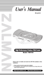
Wood Parts and Part Numbers
A-Right Leaf
B-Left Leaf
D-Left Sidel_anel
E-Right Side Panel
ge
G-Back
F-Partition
H-Compartment
Back
(Left View)
I-Shelf
....
.... /
J-Compartment
Bottom
/7
P-Drawer
M-Platform
•
L-Right
K-Left
Leaf Supports
.
Front
•
Bottom
Q-Drawer
o/
O-Door
Ref. No.
Description
Oak
White
Cherry
A
B
Right Leaf
Left Leaf
003283
003284
003220
003221
003103
003104
C
D
Top
Left Side
003288
003286
003225
003223
003108
003106
E
F
Right Side
Partition
003285
003287
003222
003224
003105
003107
G
Back
003298
003235
003119
H
I
Compartment
Shelf
Back
003293
003289
003230
003226
003112
003109
J
Compartment
Bottom
003290
003227
003110
K
Left Leaf Support
003271
003218
003116
L
M
Right Leaf Support
Platform
003282
003297
003219
003234
003117
003118
N
Front
O
Door
P
Drawer
Q
Drawer
Part No.
Wing
Wing
003296
003233
003115
003295
003232
003114
Front
003294
003231
003113
Bottom
003161
003161
003161
Page18
98300-19
98301-18
98302-181
(JJ)
(cc)
}o))o
I
o
0
(o)
D_
o
0
(KK)
(DD)
(uu)_
(E)_u__u_,
(LL)
(F) _\m_l
(EE)
@
(MM)
(V' ,FFI
(X) _
(GG)
(oo)
(HH)
(L) _\-_'_-_-_-_
(PP)
h--
(ss)
,.,© @
(N)
(z)
(11)
(ID
@
(AA)
(vv)
(AA),@
(RR)
(o)
(P)
0
98300-1!
(BB) _Page 19
98301-19
98302-19
Part Numbers
:lef. No. Description
A
#5xl/2" Flathead Screws
B
#6x5/8" Panhead Screws
C
_8xl/2" Panhead Screws
D
#8x5/8" Flathead Screws Bronze
E
#6x1" Flathead Screws
F
7/8" Knob Bolt (98301)
G
Head Mounting Bolt
H
Wing Nut
I
Zinc Flat Washer
J
19mm Cams
K
Connecting Bolts
L
6mm Hex Head Bolt
M
6mm Hex Nut
N
Round Magnet
O
Bronze Strike Washer
P
Strike Plate
Q
Caster Insert
R
Caster Clip
S
Magnet
T
Handle (#98300-98302 only)
U
Handle (#98301 only)
V
Drawer Runner
W
Allen Key
X
#5x5/8" Flathead Screws
Y
Hinge (Leaf Support)
Z
Drawer Corner Connectors
Part No.
000916
000083
002614
002570
001325
000185
002890
Ref. No.
AA
AA
BB
CC
DD
EE
FF
GG
HH
II
JJ
KK
LL
MM
NN
OO
PP
QQ
RR
000488
000220
000709
002892
003175
003176
002854
000839
002192
000368
000324
001644
003169
003145
002397
000712
003172
002734
0O3142
Page 20
Description
Knob White Ceramic
(#98301
only)
Knob Gold (#98300-98302 only)
Locking Caster
Non-Locking Caster
Right Wing
Left Wing
Plastic Tray
Drawer Side
Drawer Back
Lift Mechanism
Door Hinge
Leaf Hinge
Drawer Front Clip
Large Tray
Tote Tray
#6x1" Panhead
#8/32x1"
Handle Screw (98301
Knob Bolt (98300-302)
Custom Fit Insert Hook
Self Sticking Rubber Tab
SS
TT
UU
#8x5/8"
VV
#8132x314" Metal Handle Bolt (98300-302)
6mm Lift-Wing Washer
Manual
Leaf Hinge Screws Yellow
PaN No.
003165
003170
001135
001136
003193
003194
003146
003140
003152
003167
002613
002733
003138
003158
002869
003177
003192
002251
003174
003190
003149A
003173
003191
98300-20
98301-20
98302-20
API Specialty Furniture
(A Division
of ARROW
PRODUCTS,
P.O. Box 410, Elkhorn,
Inc.)
Wl 53121
1-800-533-7347
09-99
98300-BC
98301-BC
98302-BC