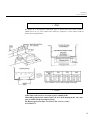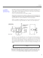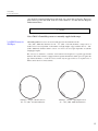
1
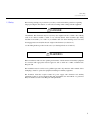
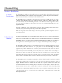
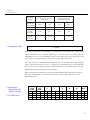
CHANNELMAG FLOWMETERS
FOR OPEN CHANNELS AND NON- FULL PIPES
Instruction Manual
RTM- Expolink s.r.o., Prikop 8, 60200 Brno, Czech Republic
FOREWORD
This instruction manual is designed to help you gain a thorough understanding of the operation of the equipment. ARKON
recommends that you read this manual completely before placing the equipment in service.
Although ARKON designs reliability into all equipment, there is always the possibility of a malfunction occurring. You can use
this manual to help in diagnosing and repairing the malfunction, if possible.
If the malfunction persists, call or write the ARKON Customer Service Department for assistance.
Address and contact information:
RTM- Expolink s.r.o.,
Prikop 8, 60200 Brno,
Czech Republic
Tel: +420 545 175 834. Tel/ Fax: +420 545 175 684
Email: [email protected]
Website: www.arkon.co.uk
For other countries, consult your nearest ARKON representative. Simple difficulties can often be diagnosed over the phone. If it is
necessary to return the equipment to the factory for service, please read our terms and conditions, available on request or from our
website.
ARKON welcomes suggestions that would improve the information presented in this manual or enhance the operation of the
equipment itself.
2
IMPORTANT – PLEASE READ
DANGER
The installation and operation of this product may put you at risk of serious injury or even death. Take whatever precautions are
necessary to ensure your safety before making an installation or working on one. Never work alone or unsupervised. Install and
operate this product in accordance with all applicable safety and health regulations, as well as any appropriate local ordinances.
This product may be installed in confined spaces. Examples of confined spaces are manholes, pipelines, digesters, and storage
tanks. These places can be dangerous or fatal if you are not suitably prepared. The primary hazards of confined spaces are the
possibility of poisoned air and the lack of proper ventilation. Work in such places is governed by OSHA 1910.146, and may
require a permit before entering. The other major hazard particular to this product is its extreme weight, which makes it dangerous
to handle and creates the risk of being crushed or struck by the unit during installation.
This manual may also contain Material Safety Data Sheets (MSDS) for chemical agents supplied or recommended for use with this
product. If needed, these sheets will be in the MSDS Appendix. These sheets provide information about possible hazards from the
chemicals. Additional MSDS, covering various proprietary agents (name-branded or trademarked mixtures) that can also be used
with this product, are available from the manufacturers of those agents.
This manual uses the following notations to set apart hazard warnings and notes:
DANGER
DANGER describes situations that will result in loss of life or serious personal injury, unless avoided. The emphasis is on clear
and immediate threats to your life or safety.
WARNING
WARNING describes situations that could result in loss of life or serious personal injury unless avoided. The emphasis here is on
the potential for a serious accident
CAUTION
CAUTION describes situations that may result in moderate personal injuries, property damage, or damage to the equipment, unless
avoided
Note
NOTES draw your attention to particular features, practices, tips, or other information useful in setting up or operating the product.
3
ChannelMag
Table of Contents
Section 1 Introduction
1.1 Scope: ChannelMag CM2
1.2 Scope: ChannelMag PM2
1.3 Safety
66
77
88
Section 2 Installation
2.1 Media Considerations
2.2 Location and Mounting
2.3 Straight Lengths of Channel / Pipe
2.3.1 Straight Lengths of Channel (CM2)
2.3.2 Straight Lengths of Pipe (PM2)
2.3.3 Important Note
2.4 Installation, Dimensions and Approximate Weights
2.4.1 CM2 Sensors
2.4.2 Installation of 2 x CM2 ChannelMag Sensors
2.4.3 CM2/D Dimensions and Approximate Weights
2.4.4 PM2 Sensors in Full Pipes
2.4.5 PM2 Sensors in Non-Full Pipes
2.4.6 Installation of PM2 Sensors With Magnetic Enhancement Band
2.4.7 ChannelMag PM2 Enhancement Plate Expander Mechanism
2.4.8 ChannelMag PM2 Weights and Dimensions
2.5 Grounding
2.6 Cable Types
2.6.1 ChannelMag Junction Box Wiring Diagram
2.6.2 ChannelMag Entela Approval
2.7 Cable Runs From the Junction Box
9
9
10
10
10
10
10
10
11
11
11
11
13
13
14
14
15
15
16
16
1717
18
18
18
18
18
18
19
19
20
20
21
21
21
21
Section 3 Calibration Data
3.1 Calibration and Range Factors
22
22
Section 4 Maintenance
4.1 Cleaning
4.2 Zero Span Checking
4.3 Effect of Moisture Ingression
4.4 Effect of a Grounded Electrode
4.5 Effect of One CM2 of Two Inoperative
4.6 Transmitter Fault
4.7 All Checks Good, But No Signal
23
23
2323
2323
23
23
2323
2424
2424
4
Table of Contents
4.8 Erratic Signal
4.9 Signal or Indication “Swing”
24
24
24
24
Section 5 Recommended Spares
5.1 Recommended Spares
2525
5
ChannelMag
Section 1 Introduction
1.1 Scope:
ChannelMag CM2
The ChannelMag CM2 is suitable for open channels having diverse cross sectional shapes from 6” to
200 feet (150 mm to 60 m). They meet or exceed the requirements of ISO 9213 and are calibrated in a
long open tank, believed to be the largest NIST traceable facility available. The ChannelMags are
calibrated in accordance with ISO* approved methods. Each ChannelMag system is normally supplied
with a NIST traceable Calibration Certificate.
Magnetic enhancement plates are fixed to and calibrated with ChannelMag sensor types CM2/8” –
40”. The enhancement plates are purposely made to the required shape of the channel, to widths or
diameters from 10” to 15 feet (250 mm to 3 m). Their purpose is to determine the distribution pattern
of magnetic flux on calibration in ARKON test laboratory and to insure it is the same as the
distribution on-site. In this way, the test calibration is the same as on-site. For channels less than 10”
(250 mm) or wider than 15 feet (4500 mm), or when used with ChannelMag type CM2/D, the
effectiveness of the enhancement plates is minimal, so they are not normally supplied.
ChannelMag CM2 sensors generate a powerful magnetic field over the whole or significant area of the
channel. They operate using Faraday’s Law, where a conductor moving in a magnetic field induces a
voltage, the amplitude of which is proportional to the velocity of the conductor. The conductor is the
media being measured. Large conical electrodes on the CM2 sensor measure the voltage signal, which
is the mean velocity of the complete cross sectional flow and is unaffected by media viscosity or
density.
Volumetric flow is computed in the 4411e by multiplying level x mean velocity. The level signal from
a diverse range of cross sectional shapes can be linearized in the 4411e. Level is measured normally
by a high resolution ultrasonic level transducer. If the level sensor needs to be hidden from view, or if
there is substantial froth on the media surface, then a high resolution pressure transducer is used under
the ramps of the CM2 sensor.
6
Chanel Mag
Section I Introduccion
1.2 Scope:
ChannelMag PM2
The ChannelMag PM2 Series is suitable for full or partially full pipes from 20” to 120” (500 3000 mm). They meet or exceed the requirements of ISO 9213 and are calibrated in a long open
tank, believed to be the largest NIST traceable facility available. ChannelMags are calibrated in
accordance with ISO approved methods. Each ChannelMag system is normally supplied with a
NIST traceable Calibration Certificate.
Magnetic enhancement plates are fixed to and calibrated with the ChannelMag sensor(s). The
enhancement plates are custom made to the required diameter of the channel. Their purpose is to
determine the distribution pattern of magnetic flux on calibration in ARKON test laboratory and to
insure it is the same as the distribution on-site. In this way, the test calibration is the same as onsite. The other function of the enhancement plates is to retain the ChannelMag sensors in place in
the pipe. They incorporate an expander mechanism which holds the sensor(s) firmly in place,
without the need of further fixtures or to cut holes in the pipe.
ChannelMag sensors generate a uniquely powerful magnetic field over the whole cross sectional
area of the pipe. They operate using Faraday’s Law, where a conductor moving in a magnetic field
induces a voltage, the amplitude of which is proportional to the velocity of the conductor. The
conductor is the media being measured. Large conical electrodes on the PM2 sensor measure the
voltage signal, which is the mean velocity “weighted” to account for the complete cross sectional
velocity profile. The signal is unaffected by media viscosity or density.
Volumetric flow in partially filled pipes is computed in the 4411e by multiplying level x mean
velocity. The level signal is linearized in the 4411e. Level is measured normally by a high
resolution pressure transducer, which is used under the ramps of the ChannelMag velocity sensor.
This has the advantage of being supplied with the PM2 sensor as a single unit, as well as being
virtually insensitive to froth on the surface of the media. However, an ultrasonic level transducer is
available, which must be mounted in a suitable manhole.
7
ChannelMag
Section 1 Introduction
1.3 Safety
The following warnings are provided for your safety. You should read the general note regarding
danger preceding this introduction, as well as these warnings when working with this equipment:
DANGER
Crush hazard. The flowmeters may be very heavy (net weights from 45 to 450 lb / 20 to 200 kg
each). You could be crushed to death, or very seriously injured, if the flowmeter slips during
installation and strikes you or falls on you. Handle with care when installing and be sure that
hoisting apparatus can safely lift the total weight of the flowmeter (see Section 5.1).
Use the lifting brackets provided on the sensor (see drawing in Sections 2.2 and 2.4).
WARNING
Before installation, make sure the operating environments of the flowmeter and ancillary equipment
are consistent with appropriate national approvals such as USA UL or NEC, Canadian CSA,
European CE.
The installation must be carried out by qualified personnel only. Read the entire manuals before
attempting to install or operate the equipment, including for ancilliary equipment.
The flowmeter electronics require normal AC power supply. The flowmeter and ancillary
equipment produces no electro-magnetic fields that are harmful to the environment or to personnel.
They are certified as such to meet European CE requirements.
8
ChannelMag
Section 2 Installation
2.1 Media
Considerations
The ChannelMag is suitable for such media as water, raw sewage, slurries, algae laden river water, and
similar. The minimum media conductivity is 0.5 microS/cm for operation with pulsed AC transmitters.
Most water based media has a conductivity of 200 – 800 microS/cm.
The ChannelMag may be permanently coated with sewage grease, algae, calcium carbonate, iron oxides
or similar, without affecting accuracy. No cleaning is necessary. If there is non fluidic sediment on the
bed of the channel, then the ChannelMag should sit on the channel bed with its upper-most surface
above the channel bed. Ramps are then required (see Section 2.2). All PM2 ChannelMag sensors are
supplied with ramps.
Check the compatibility of the media with the wetted parts before installing. With some media its
consistency and operational temperature range can affect this compatibility.
Make sure the pressure of the media acting on the sensor(s) and the operational temperature does not
exceed that specified.
2.1 Location and
Mounting
For lifting the ChannelMag sensor, use the lifting brackets fixed to the sensor, as shown on the drawing in
Section 2.4. Use a min. diameter 1/8” (3mm) steel rope looped through the bracket holes for installing the
ChannelMag sensors(s). Use the holes in the magnetic enhancement plates ONLY for convenience of
removing the sensors from flowing media, since in so doing the enhancement plates may be damaged.
The ChannelMag is highly insensitive to environmental electrical noise, including interference from radio
and variable frequency drives. However, it is good practice to locate the ChannelMag and ancillary
equipment away from the immediate area of such noisy environments. The ancillary electronics must be
located remotely from the ChannelMag sensors. They must not be mounted under direct sunlight, or
where they are subject to driving rain, where they cannot be reasonably read or serviced. For such
environments they must be protected by a suitable canopy or protective housing. Avoid environments
where moisture can accumulate in the electronics. A heated enclosure may be necessary to achieve this.
The ChannelMag sensors are indefinitely submersible to 30 feet (10m)/ 15 psig/1 bar g. They are normally
supplied with conduited cables and junction box (see data sheet in this instruction manual for details of
lengths). Should the cables be extended then each cable may be spliced, soldered and all cable joint
surrounded with shrink sleeves. Shielding must be extended to the same length as all other cable cores.
Should a junction box be used to extend cables, it must be absolutely dry, then fi lled with potting
compound. We recommend 3M “High Gel” type 4442 two part, re-enterable compound, mixed 50% / 50%
. The typical drying time is 2 – 3 hours, but it never solidifies hard. A metal shield 1/16” (1-2mm) thick
must be placed between
9
ChannelMag
Section 2 Installation
the electrode cables and the energizer coil cable within the junction box. Do not use silicone rubber
(RTV) for potting, since it contains acetic acid which can corrode the junction box terminals.
Make sure the serial number of the ChannelMag sensor(s) shown on the cables agrees with the
serial number of the transmitter. This is particularly important when more than one ChannelMag
flow system has been supplied. If a sensor and transmitter have been supplied separately, then the
transmitter range factor has to be adjusted according to the sensor calibration (see transmitter
instructions).
Although the ChannelMag sensor is bi-directional, make sure the ChannelMag is installed in the
channel with the flow direction arrow consistent with the actual flow direction of the media. If it is
not, then the electrode cable terminals in the remote transmitter may be switched around (see
separate transmitter instruction manual). The accuracy and flow calibration factor is identical in
both directions.
2.3. Straight Lengths of
Channel / Pipe
2.3.1 Straight Lengths
of Channel (CM2)
The CM2 ChannelMag must be installed in a channel with a minimum of 7 straight channel widths
upstream and 4 straight channels downstream, as shown in the diagram below. For bi-directional
use a minimum of 7 straight channel widths are required upstream and downstream.
The straight lengths are measured from the end of the ramps. When ramps are not supplied (and the
ChannelMag CM2 sensor(s) is inserted into a recess in the base of the channel), then the straight
lengths are measured from the end of the CM2 sensor.
W = channel width (not necessarily the width of the CM2 sensor)7W = upstream minimum
length2W = downstream minimum length (must be 7W for bi-directional fl ow)L = overall
length with or without ramps
The ChannelMag and installation conforms to German DIN 19559 and German Waste Water
Institute (ATV Arbeitsgruppe 1.2.5) requirements.
2.3.2 Straight Lengths
of Pipe (PM2)
The ideal location in the pipe is where there is a maximum straight length. The table below
provides recommendations of minimum straight lengths of pipe for various pipe configurations.
Shorter lengths or other configurations affect published accuracy, dependant on pipe size and
velocity range. Consult ARKON or a qualified representative.
Diametrically opposite sensors are either 1 pair or 2 pair.
When an ultrasonic level transducer is used for partially filled pipe applications it must be located
at least 8” (200 mm) before or after the ends of the ramps to avoid drops in level due to sub-critical
flows, or rises in level due to super-critical flows. When the hydrostatic level transducer is
employed its level sensing position is virtually at the start of the upstream ramp and avoids critical
flow rises and falls.
10
ChannelMag
Section 2 Installation
Pipe Confi
guration
90° bend
upstream and
downstream
After a tee
Upstream
partially
closed valve
Multiple Sensors Number of
Single Sensor Number of Straight
Pipe Diameters D Upstream
Downstream
Straight Pipe Diameters D
Upstream Downstream
10 D
5D
5D
2D
15 D
5D
8D
2D
25 D
5D
15 D
2D
Downstream
partially
closed valve
8D
5D
2.3.3 Important Note
Note
When using an ultrasonic level transducer, or a hydrostatic level transducer in a stilling well, it
must be installed at least 1 channel width before or after the ends of the ramps when the
ChannelMag sensor lies on the channel bed. This avoids surface level drops directly above the
sensors caused by sub-critical flows, or level rises caused by super critical flows.
These critical flows are circumvented if the CM2 is let into a recess in the bed. As such, the upper
surface of the CM2 sensor may be up to 1” (25mm) above the channel bed to avoid silt build-up.
The ultrasonic level transducer may then be mounted directly above the CM2 sensor(s). Note the
minimum dead band for the ultrasonic level transducer.
When a hydrostatic level transducer is used it is normally installed in the ramp, with its sensing at
the point of the ramp. This also avoids critical flow drops or rises in the media level above the
ChannelMag sensor.
2.4 Installation,
Dimensions and
Approx. Weights
2.4.1 CM2 Sensors
Nominal
CM2
Width
in. mm.
8.0 200
24.0 600
40.0 1000
Actual
CM2
Width
in. mm.
10.0 254
26.0 660
42.0 1066
L
in.
40.0
60.0
80.0
mm.
1016
1520
2030
S
in.
8.0
25.0
40.0
mm.
203
610
1020
R
in.
14.5
18.0
20.0
mm.
370
460
510
H
in.
2.50
3.12
3.50
mm.
64
80
89
M
in.
6.0
12.0
24.0
mm.
152
305
610
Weight
Each
lb
55
186
355
kg.
25
85
165
11
ChannelMag
Section 2 Installation
Note
The height “E” of the magnetic enhancement plates is custom made and normally extends 2”
(50mm) below the top of the channel. The width W is adjustable to fit the channel width. W
includes the mounting brackets.
1/4” (6.3mm)
thick base plates
with countersunk
1/4” screws from
the bottom
Note: A CM2/8” sensor is always supplied with ramps.
Note
Cables from each sensor are to run in separate conduits to the
ChannelMag junction box situated above the level of the flowing media. The cable
runs are omitted in the drawing for clarity.
For Entela approval for Zone 2 or Class 1, Div. 2 areas see notes
in Section 2.6.2.
12
ChannelMag
Section 2 Installation
2.4.2 Installation of 2 x CM2
ChannelMag Sensors
Adjust width before installation into channel 2.00” 50m
Lifting brackets. Do not lift by the Actual CM2 Width enhancement plates.
For CM2 sensors installed in a recess in the bed of the channel, the installation configuration remains the same. 1/4” (6.3mm) thick base
plates with the recess must extend over the full channel width, countersunk 1/4” screws from the bottom
Advised Width of Channel
Note
The height E of the magnetic enhancement plates is custom made and normally extends to 4”
(100mm) nominally above the maximum level. The width W is adjustable to fi t the channel
width. W includes the mounting brackets.
13
ChannelMag
Section 2 Installation
2.4.3 CM2/D
Dimensions and
Approximate Weight
The CM2/D is normally used with a FMX167 hydrostatic level transducer and installed as shown
below. A 2-part re-enterable gel type 4442, manufactured by 3M Company, St. Paul, Minnesota, is
normally supplied to retain the CM2/D in the hole made for it. The 2-part gel is mixed together in
equal amounts. It makes approximately 1 gallon
(4.5 liters) of gel, which should suffice for the installation of CM2/D.
The hydrostatic level transducer must be installed in a stilling well as shown, such that the level is
not affected by the impact pressure of the flowing media. The hydrostatic pressure transducer may
be installed with its bottom most end above any silt build-up at the bottom of the channel by a
suggested maximum of 0.5” (10mm). The FMX167 ha a sealed sensing diaphragm.
Similarly to the FMX167, the CM2/D mean velocity sensor may be installed to protrude above the
bottom of the channel by a suggested maximum of 0.5” (10mm), as shown in the diagram below.
The CM2/8”, 24” and 40” ChannelMag sensors are normally supplied with mounting brackets at
each side. The mounting brackets are placed over two clearance slots cut into the Magnetic
Enhancement Plates. Base plates with fixing screws, countersunk from the bottom side are then
used to secure the CM2 ChannelMag to the Magnetic Enhancement Plates. The clearance slots
allow the Magnetic Enhancements Plates to be adjusted symmetrically about the exact width of the
channel. The width must be adjusted and secured before installing the ChannelMag into the
channel.
Note
For CM2 ChannelMags supplied without ramps, the CM2 must be placed in a recess that must be
made in the bed of the channel. The recess depth must be such that the upper surface of the
ChannelMag is not higher than a suggested ½”” (12mm) above the bed of the channel, but enough
to avoid excessive silt or similar build-up. If higher than this is necessary, then the
14
ChannelMag
Section 2 Installation
step should be cemented with an approach angle of not more than 15 degrees. The recess
must extend over the full width of the bed of the channel to accommodate the Magnetic
Enhancement Plates.
Note
Note: CM2/8” ChannelMag sensors are normally supplied with ramps.
2.4.4 PM2 Sensors in
Full Pipes
ChannelMag PM Series sensors are used for full pipe flow measurement from 20”
- 120” (500 - 3000 mm) diameter. For 20” - 47” (500 - 1195 mm) diameter a single sensor or
double sensor is used, dependant on the number of straight lengths of pipe available. For 48” - 120”
(1200 - 3000 mm) diameters either 2 sensors or 4 sensors are used, again dependant on available
straight pipe lengths.
The sensor(s) are attached to a stainless steel retention band designed for a specific pipe internal
diameter. The retention band is equipped with an expander mechanism, which opens out against the
pipe internal diameter to secure the sensors. In this way the pipe wall does not require holes or
fixtures and is ideal for concrete tunnels.
Full Pipes -- Single or Double Sensors
20” - 47” (500 - 1195 mm) Diameters
Full Pipes -- Double or Quadruple Sensors
48” - 120” (1200 - 3000 mm) Diameters
15
ChannelMag
Section 2 Installation
2.4.5 PM2 Sensors in
Non-Full Pipes
The ChannelMag PM Series sensors are used in partially filled pipes from 20” - 120” (500 - 3000
mm) diameter. For pipes 20” - 36” (500 - 915 mm) a single ChannelMag sensor is installed in a
retention band at the bottom of a horizontal pipe. For larger pipes two sensors are used at the
bottom of the pipe, with their center lines equally dispersed at 15 degrees from the pipe center.
For partially filled pipes a hydrostatic level transducer is incorporated in a ramp on the upstream
end of the sensor. The level transducer cable includes a “breather” tube, which is vented in the
remote 4411e transmitter, or in a junction box when the cable is longer than 33 feet (10 m). The
cables are run in plastic conduits to the pipe exterior.
Partially Filled Pipes -- Single Sensor
20” - 36” (500 - 915 mm) Diameters
Partially Filled Pipes -- Double Sensors
38” - 120” (920 - 3000 mm) Diameters
16
ChannelMag
Section 2 Installation
2.4.6 Installation of PM2 Sensors
With Magnetic Enhancement Band
Center spacer used for compound
sensor installation only
Outer mounting points used
without center spacer
Bands joined here
17
ChannelMag
Section 2 Installation
2.4.7 ChannelMag PM2
Enhancement Plate
Expander
Mechanism
The expander mechanism incorporates 2 left- hand and right- hand threaded rods, which when turned
with a wrench (spanner), secure the enhancement plates and sensor assembly firmly in pipe. Additional
fixtures or holes in the pipe are unnecessary.
2.4.8 ChannelMag PM2
Weights and
Dimensions
2.5 Grounding
The CM2 ChannelMag is equipped with a grounding plate, normally manufactured from AISI 316
stainless steel. This makes sure there are no unequal potentials between the media and the shielding
of the ChannelMag connection cables. For cable distances from the junction box to the transmitter
of 100 feet (30m) further grounding requirements are not normally necessary. However, for longer
cable lengths a pre-amp in the junction box is necessary.
CAUTION
Total cable distances of greater than 300 feet (100m) are not recommended, since it
increases the possibility of unequal potentials.
18
ChannelMag
Section 2 Installation
2.6 Cable Types
ChannelMags are connected to a junction box normally using cables in flexible 1” (25mm)
conduit. See the ChannelMag Sensor Specification for the standard cable and conduit lengths.
The cables and conduit are stowed for packing against the side of the Magnetic Enhancement Plates
and are marked “coils,” “electrodes,” and “reference.” The cables from the junction box to the
transmitter are without conduits and connected to the remote transmitter terminals as follows (see
separate instructions for the transmitter):
Exciter Coils
Black to 4
White to 5
Shield to 6
Electrodes
Black to 24
White to 25
Shield to 26
Reference Coils
Black to 31
White to 32
Shield to 19
The junction box is submersible and is potted with a re-enterable gel, but is not intended to be
installed in the media flowing in the channel. Cables from dual sensors are wired in the junction
box as shown below in Section 2.6.2.
19
ChannelMag
Section 2 Installation
2.6.1 ChannelMag Junction Box Wiring Diagram
BLACK
RED OR CLEAR
SHIELD
ChannelMag
Section 2 Installation
CAUTION
20
The cable ends and the junction box supplied for multi-Channel Mag systems are to
NEMA 6 and IP68 for permanent submersion to 30 feet (10m) water column. As
such, the cable ends are supplied with shrink-fit sleeves. It is important not to cut
these sleeves off during storage, as they prevent moisture permeating the cables
ends. Moisture in the cables causes signal instability. Cut the sleeves off only prior to
wiring into the transmitter. Cables must be split not more than 1” (25mm) from the
terminal entries of the transmitter. Do not coil excess cable to avoid false inductance.
2.6.2 ChannelMag
Entela Approval
ChannelMags are Entela Approved For Class 1, Div. 2 or European Zone 2 Areas:
1.
2.
3.
For a single ChannelMag sensor or remote junction box for use with multiple
ChannelMags sensors used in applications Entela approved to CSA and NEC standards
for Class 1, Division 2 areas, or the European ATEX Zone 2 areas, the remote 4411e
transmitter must be used in the safe area. It is a requirement of approval for CSA and NEC
that cables must run in conduits for the connection of the ChannelMag sensor(s) to the
transmitter. Conduit connectors are provided for this. For ATEX Zone 2 requirements
conduit is not necessary.
For a single ChannelMag sensor or remote junction box for use with multiple
ChannelMag sensors that are Entela approved to ATEX Zone 2 standards, it is conditional
that the reference coil, exciter coil and electrode cables emanate from 3 separate cable
glands. Alternatively, the reference coil and exciter coil may run in a 4-core cable,
consisting of 2 x 2 core, each pair individually shielded and where the 2 core shielded
electrodes cable is separated from it. All such cables must be IEC approved and is
normally supplied by ARKON. The IEC cables may have identification other than black
and white, but they will be clearly labeled.
All ChannelMags and junction boxes must be potted with 3M re-enterable gel type 4442
or type 8882. This is normally supplied with a junction box for each system.
Dual ChannelMag sensors are normally supplied with a remote dual entry junction box and is
wired as shown below. For single sensor ChannelMags Sensor 2 on the diagram is omitted.
2.7 Cable Runs From
The Junction Box
Cables running greater than 30 feet (10m) after the junction box to the transmitter must have the
electrode pair cable separated from the exciter coil pair cable by a minimum of 2 feet (0.5m). The
reference coil pair cable may be run in the same conduit as the electrode pair cable. The maximum
cable length is limited to 300 feet (100m). See Section 2.5.
21
ChannelMag
Section 2 Installation
For multiple ChannelMag systems, the electrode and reference cables may all run in the same
conduit to their respective transmitters, but separated from the exciter coil cables by a minimum of
2 feet (0.5m). Multi-exciter coil cables may all run together in a single conduit, even with other
power cables. Again, the multi-exciter coil cables must be separated from the reference and
electrode cables by a minimum of 2 feet (0.5m).
3.1 Calibration and
Range Factors
The calibration data is provided on the NIST traceable Calibration Certificate, as well as on a label
inside the 4411e transmitter. Details of adjustments in a fl ow range are provided in the 4411e
instruction manual.
22
ChannelMag
Section 4 Maintenance
4.1 Cleaning
Under typical operating conditions the ChannelMag sensor requires no maintenance. Due to the
uniquely high signal to media noise ratio, the affects of such coatings as algae, sewage grease,
calcium carbonate, iron oxides or similar coatings have no affect on published accuracy. As such
cleaning of coatings is normally unnecessary.
Should there be silt or similar non-fluidic build up, the upper surface of the ChannelMag sensor
must be cleaned. However, with the ramp construction the upper surface it is highly unlikely to
become covered with silt or similar.
When the CM2 is in a recess in the bed of the channel, it is recommended to have its upper surface
slightly above the bed of the channel, but not more than ½” (12mm). This avoids excessive silt or
similar build up, as well as avoiding too much turbulence due to the step from the bed to the upper
surface. If more than ½” (12mm) is required, then the step to the upper surface should have suitable
grouting at an angle of less than 15 º.
4.2 Zero Span Checking With the ChannelMag sensor connected to the 4411e transmitter, check for zero and span in
accordance with the 4411e Instruction Manual. This confirms the electrical function of the
transmitter.
Note: Bad grounding will not affect the electrical zero and span test.
4.3 Effect of Moisture
Ingression
The exciter coils of the ChannelMag sensor should be checked at the transmitter end. Remove from
terminals 4, 5 and shield 6. There should be a minimum 10Meg Ohms (typically > 20Meg Ohms)
between 4 and 6 and 5 and 6 respectively. If there is less than 10Meg Ohms, moisture has probably
leaked into the sensor and /or the cable, resulting in signal instability. The cable should be inspected
for damage or dried out or cut away where any moisture may be. If the sensor has leakage it must
be returned to ARKON or approved representative.
4.4 Effect of a
To check if there is electrical ground at the electrodes, the cable ends 24 and shield and 25 and
shield respectively are removed from the terminals of the transmitter. The resistances should
approximately the same between each and between 100k Ohms to 5 M Ohms. If any electrode is
grounded the signal will be at approximately ¾ of the normal signal. Remove anything highly
conductive between the appropriate electrode and ground.
Grounded Electrode
4.5 Effect of One Sensor If there are two ChannelMag sensors used as one flow system in a channel, the electrodes and coils
Of Two Inoperative are wired in parallel. Should one sensor coil become defective, then the system will continue to
operate, but there will be a small inaccuracy due to operating with only one sensor. If this is
unacceptable a replacement sensor can be installed at a convenient time. The erroneous sensor can
be determined by checking as above in the junction box.
23
ChannelMag
Section 4 Maintenance
4.6 Transmitter Fault
Should the resistances referenced above be correct, but the zero and span cannot be achieved, then
the fault lies with the transmitter.
4.7 All Checks Good,
But No Signal
Check wiring in transmitter terminals in accordance with the transmitter instructions. Make sure
there is actually flow through the channel.
4.8 Erratic Signal
Check the following:
a) Make sure the ChannelMag sensor is fully covered with media.
b) Check Paragraphs 4.1.4 to 4.1.6
c) Check if the ChannelMag sensor is correctly grounded (see Section 2.5)
d) Check for loose wiring.
e) Make sure cables are not too long. For multiple ChannelMag systems make sure electrode
cables are separated from other cables (see Section 2.7)
f) The ChannelMag has high insensitivity to radios and variable frequency drives. If these are
in close proximity to the transmitter or sensor then cable lengths should be kept to an
absolute minimum.
4.9 Signal Or Indication Check the following:
a) Make sure there is enough straight length of channel (see Section 2.3). If the requisite
“Swing”
straight lengths are not available, then the “damping” in the transmitter must be maximized
(see transmitter Instruction Manual).
b) Make sure there are no flow pipes or channels entering the channel in the location of the
ChannelMag sensor .
c) Make sure there is no debris or loose cables in the vicinity of the electrodes.
24
ChannelMag
Section 5 Recommended Spares
5.1 Recommended
Spares
Since the ChannelMag sensor is a solid state sensor, completely encapsulated, there are no
recommended spares.
Make sure when ordering a new ChannelMag sensor or transmitter that the serial number found on
the transmitter label is advised.
When a new ChannelMag sensor is provided it has a new Calibration Certificate. Make sure the
new calibration factor is entered into the transmitter in accordance with the appropriate transmitter
Instruction Manual.
25