1
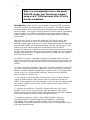
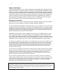
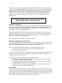
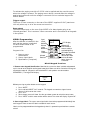
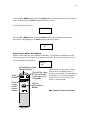
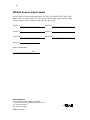
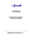
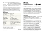
GSZ67 12 Channel Eco-System™ Controller-Amplifier Installation Instructions v1.3 2 Important Safety Instructions: 1) Read these instructions. 2) Keep these instructions. 3) Read all warnings. 4) Follow all instructions. 5) Do not use this apparatus near water. 6) Clean only with dry cloth. 7) Do not block any ventilation openings. Install in accordance with the manufacturer’s instructions. 8) Do not install near any heat sources such as radiators, heat registers, stoves, or other apparatus (including amplifiers) that produce heat. 9) Do not defeat the safety purpose of the polarized or grounding-type plug. A polarized plug has two blades with one wider than the other. A grounding type plug has two blades and a third grounding prong. The wide blade or the third prongs are provided for your safety. If the provided plug does not fit into your outlet, consult an electrician for replacement of the obsolete outlet. 10) Protect the power cord from being walked on or pinched particularly at plugs, convenience receptacles, and the point where they exit from the apparatus. 11) Only use attachments/accessories specified by the manufacturer. 12) Use only with the cart, stand, tripod, bracket, or table specified by the manufacturer, or sold with the apparatus. When a cart is used, use caution when moving the cart/apparatus combination to avoid injury from tip-over. 13) Unplug this apparatus during lightning storms or when unused for long periods of time. 14) Refer all servicing to qualified service personnel. Servicing is required when the apparatus has been damaged in any way, such as power-supply cord or plug is damaged, liquid has been spilled or objects have fallen into the apparatus, the apparatus has been exposed to rain or moisture, does not operate normally, or has been dropped. 15).Under no circumstances should the output terminals of the amplifier be short-circuited. 16).Be sure that the loudspeakers connected can handle the output power of the amplifier at the loudspeakers rated impedance. The warranty on the amplifier does not cover damage to loudspeakers that have inadequate power handling capabilities. 17) A push button is used to turn the power off and on. 18) When the front panel push button switch is in the in position the apparatus is powered on. CAUTION: These servicing instructions are for use by qualified service personnel only. To reduce the risk of electric shock do not perform any servicing other than that contained in the operating instructions unless you are qualified to do so. Note: The apparatus shall be connected a mains socket outlet with a protective earthing connection. Note: Where the mains plug or an appliance cover is used as the disconnect devise, the disconnect devise shall remain readily operable. WARNING: This product contains chemicals, including lead, known to the State of California to cause birth defects or other reproductive harm. Wash hands after handling. 3 FCC Warning Note: This equipment has been tested and found to comply with the limits for a Class B digital device, pursuant to part 15 of the FCC Rules. These limits are designed to provide reasonable protection against harmful interference in a residential installation. This equipment generates, uses and can radiate radio frequency energy and, if not installed and used in accordance with the instructions, may cause harmful interference to radio communications. However, there is no guarantee that interference will not occur in a particular installation. If this equipment does cause harmful interference to radio or television reception, which can be determined by turning the equipment off and on, the user is encouraged to try to correct the interference by one or more of the following measures: • • • • Reorient or relocate the receiving antenna. Increase the separation between the equipment and receiver. Connect the equipment into an outlet on a circuit different from that to which the receiver is connected. Consult the dealer or an experienced radio/TV technician for help. Canada This Class B digital apparatus complies with Canadian ICES-003. Cet appareil numérique de la classe B est conforme à la norme NMB-003 du Canada. Caution: To reduce the risk of electrical shock, do not remove the cover (or back). No user serviceable parts inside. Refer to qualified service personnel. Warning: To reduce the risk of fire or electric shock, do not expose this appliance to rain or moisture. The lightning flash with arrowhead, within an equilateral triangle, is intended to alert the user to the presence of uninsulated “dangerous voltage” within the products that may be of sufficient magnitude to constitute a risk of electrical shock to persons. The exclamation point within an equilateral triangle is intended to alert the user to the presence of important operation maintenance (servicing) instructions in the literature accompanying the appliance. 4 Note: It is very important to use a top quality RJ45 8/8 crimper tool. We strongly suggest using a cat 5 / RJ45 electronic tester to verify the wire conductors. Introduction: Thank you for your purchase of a Knoll GSZ67 12 channel controller amplifier and congratulations on your choice. The GSZ67 features six deluxe digital volume controlled stereo amplifiers with individual seven source selection. This is Knoll's third generation of multi-channel, high-quality power amplifiers. The GSZ67 is designed to meet the amplifier needs of custom installed multi-zone systems where high quality sound is a specific requirement. Each of the six zones or rooms can select any of the seven inputs, with individual volume control, bass, treble and balance. Extras such as an external voltage trigger that can turn source equipment on and off, individual zone infrared outputs, a fully balanced paging override, RS232 control, fully buffered line level outputs and many more features give the GSZ67 exceptional value when installed in homes and large complex systems. Except for the power button all controls are rear mounted. A data port is provided for ganging multiple GSZ67's. Infrared signals can be relayed from the keypads to the source equipment. The GSZ67 is normally controlled by MR164 LCD keypads with or without Knoll remote controls or RS232 commands from whole house controllers. The paging override is normally used for whole house announcements or doorbell chimes. Seven input source selection. Each of the six stereo amplifiers is provided with seven input source selection. Selection, volume level, bass, treble and balance is made on MR164 keypads, Knoll remote control (or a programmed remote control) or via an external controller. Rooms can have different source selections, volumes, etc. Six internal 80 position stereo volume controls. The six zones can each require a MR164 keypad, RB12 remote control or external controller via RS232. The keypads are typically mounted in the room with the speakers and they control amplifier power on/off, volume up/down and mute as well as source selection. Cost and size efficiency. The GSZ67 consists of a total of 12 power amplifiers in one 3-1/2" high enclosure (two rack spaces). Each power amplifier channel can deliver 50 watts RMS with peaks of 100 watts. Because of its unique design the GSZ67 delivers exceptional value. Automatic protection circuitry. Each GSZ67 amplifier channel is individually and fully protected against low impedance, overheating, overloading, over voltage and under voltage. The protection circuitry automatically restores the amplifier channel as soon as its parameter returns to the safe operating area. 5 Individual bass, treble and balance adjustment. Each channel features adjustments so installers can preset the room for speaker differences and listener preferences. External trigger. The GSZ67 can turn on and off source components with its 12vdc trigger output. All zone control. The MR164 keypad features all zone control of all off, all zones to any one source (then set volume at 1/3) and all zones volume up or down. GSZ67 includes a quiet thermostat controlled internal fan to increase its long-term power output capability. Infrared controller ports. Each zone or room has its own infrared output jack. An all zone jack is also provided. Zones 5 and 6 have controlled line level outputs so larger power amplifiers can be connected to these outputs. Optional rack mount version. Occupies two rack spaces. Unpacking: The carton and packing materials used in shipping your new amplifier were specially designed to protect it from the shock and vibration of shipping. We suggest that you save the carton and packing materials to use if you move, or if the unit ever needs to be shipped back to us for any reason. Should you discover that your amplifier has been damaged during shipping, please contact your dealer or Knoll immediately and request the name of the carrier so a written claim can be made. The right to a claim against a public carrier can be forfeited if the carrier is not notified immediately in writing and if the shipping carton and packing materials are not available for inspection by the carrier. Save all packing materials until the claim is settled. GSZ67 placement During normal home operation the amplifier will become warm. However, there are instances during high-level playback into low impedance speakers when the amplifier will become much warmer than normal. To ensure the amplifier’s trouble-free operation, it is necessary to provide adequate ventilation. Your amplifier should be kept away from external sources of heat such as radiators and hot-air ducts. The amplifier should never be placed with other heat-producing components in a cabinet or enclosure lacking free airflow. Do not stack other components on top of your amplifier. Connecting your amplifier When making connections between any source components and the amplifier, or when making connections to any speaker, be certain that both the input devices and the amplifier are turned off. Unplug all equipment before making any connections so that there will be no unwanted signal transients that can damage equipment or speakers. 6 Input connections Connecting the GSZ67 to your source equipment is straightforward. Using the highquality RCA audio interconnect cables, match the output channel designations on the rear of your source equipment to the input jacks on the rear panel of your amplifier that have the same channel name. When making connections with RCA type plugs on interconnect cables, make certain to gently, but firmly, insert the plug into the jack. Loose connections can cause intermittent sound and may damage your speakers. Some quality RCA plugs may be very tight, and it is important to secure a proper connection between the interconnection cable and the input jack. Speaker connections The GSZ67 has six stereo 50 watts per channel amplified outputs. Channels 5 and 6 also have line level outputs to connect to larger powered amplifiers. To ensure that the high quality signals produced by your amplifier are carried to your speakers without loss of clarity or resolution, Knoll advises that you use high-quality speaker wire. Many brands of wire are available — the choice may be influenced by the distance between your speakers and the amplifier, the type of speakers you use, personal preferences, along with other factors. Regardless of the brand or type of speaker wire chosen, we suggest that you use a wire constructed of fine, multi-strand copper with a gauge of 16 or less (the lower the number, the thicker the cable). Wire with a gauge of 16 may be used for short runs of less than 12 feet. We do not recommend that you use any wires with an AWG equivalent of 18 or higher due to the power loss and degradation in performance. To connect the amplifiers to your speakers, a removable plug with screws is provided for each stereo channel output. Strip approximately 1/4 inch of insulation from the end of each wire and carefully twist the strands of each conductor together. Be sure not to cut the individual strands or twist them off. All strands must be used for optimal performance. Insert the wire into the plug and screw the screws very tight. Inspect that no wire “hairs” that can short circuit are not in the plug. Correct polarity connections are important to maintain proper speaker phasing. When speaker phasing is correct, all speakers move in and out at the same time preserving the imaging of the program material. Out-of-phase connections mean that some turn off, check your speakers to verify that they are operating properly. If all other potential sources of trouble check out properly, contact Knoll for further assistance. Run the cables to speaker locations. Do not coil any excess cable, as this may become an inductor that creates frequency response variations in your system. Lastly, connect the wires to the speakers, again being aware of proper polarity. Remember to connect the negative, or black wire, to the matching terminal on the speaker. The positive, or red wire should be connected to the matching terminal on the speaker. Note: While most speaker manufacturers follow industry convention of using red terminals for positive connections and black terminals for negative, some manufacturers may vary from this configuration. To ensure proper phase connections, and optimal performance, consult the identification plate on our speaker terminals, or the speaker’s manual to verify polarity. Contact the speaker’s manufacturer if you do not know the polarity of your speakers. 7 RS232 Connection The RS232 connection is used to control the GSZ67 by an external controller or computer and can work with our without keypads. The GSZ67 connects to the RS232 controller with a 9-pin db9 connector. The programming reference follows. RS232 Terminal Settings To control the amplifier from a PC environment, connect a standard RS-232 cable from to a PC or other device (which can run a terminal emulator) to the serial port on the amplifier. Windows “Hyper Terminal” will be used for examples. Setting Baud Data Bits Stop Bits Parity Flow control Emulation Value 9600 8 1 none none auto detect RS232 Command Summary All commands consist of three alpha characters followed by request, all enclosed in parentheses. The request can be in some cases a read request (followed by a “?”), or a write request (followed by 0-3 ASCII digits). A read command will return the current setting, and write command will change the setting. A read request format: (nAA?) where: ( starts the command n denotes amplifier channel AA denotes the command ? denotes the read request ) ends the command Example: Function Volume Command (1vl?) Response returns the volume on channel 1 (0-80) A write request format (nAA###) where: ( starts the command n denotes the amplifier channel AA denotes the command ### denotes the value to be written if req’d (leading zero’s ARE necessary) ) ends the command Example Function Command Response On/Off Select Input Set Volume (1on) (1sl7) (1vl60) turns on amplifier channel one selects input channel 7 to amp channel 1 selects volume on amplifier channel one to be set at a value of 60 8 Some commands are read or write only – for example, mute all is a write only command, whereas version is a read only command. n = numerical ascii value, where needed (“all” commands do not require) # = second numerical ascii value [] = optional command, do not include square brackets in actual command Function Command Range Read/Write Version Reset Channel On Channel Off Mute Unmute Mute All Unmute All Vol (vr?) (rx) (non) (nof) (nmu) (num) (amu) (aum) (nvl [? Or ## ]) read only write only write only write only write only write only write only write only read or write, note 1 Vol All Input Select (avl##) (nsl#) Input Select All (asl#) none none n = 1-6 n = 1-6 n = 1-6 n = 1-6 none none n = 1-6 ## = 0-80 ## = 0-80 n = 1-6 # = 1-7 # = 1-7 Bass (nb#) Treble (nt#) n = 1-6 # = 0-F n = 1-6 # = 0-F write only write only write only write only, hex write only, hex Note 1: Read on Volume returns decimal value RS232 Sample Command String Audio out of Channel 1, Input source 7, Volume = 35, Bass Up, Treble Down, from “off”. (1on) (1um) (1sl7) (1vl35) (1ba) (1t4) turn on channel 1 unmute channel 1 select input 7 to channel one set volume to 35 turn bass to Hex value “A”, which is Decimal 10 turn treble to Hex value “4”, which is also Decimal 4 9 Keypad Connection The GSZ67 outputs can be controlled by the MR164 keypad and/or an external controller or computer (using the RS232 port), so keypads may not be needed. More than one or two keypads can be used in a zone and nine (9) is the maximum number of MR164 keypads per GSZ67 allowed. Note: MR164 keypads are not designed for outdoor use, high humidity, high temperatures or any extremes. The MR164 contains an almost all brand infrared repeater and most functions can be controlled by the Knoll RB12 remote control. RB12 commands can easily be stored in a learning remote. The MR164 is connected to the GSZ67 with CAT5 or CATe wire. Each keypad can have a home run or be daisy chained on one wire. If you daisy chain one zone and another zone on one wire you may lose some infrared functionality. Each room or zone has a unique IR pass-thru port as indicated on the rear of the GSZ67. In addition there is an all room IR pass-thru port. If you combine two or more rooms or zones on 1 CAT5 wire the ability to individually split infrared signals will be lost. Each keypad has two RJ45 connectors that are both inputs and outputs for daisy chaining keypads together. Five of the eight CAT5 wire conductors are used. Note: It is very important to use a top quality RJ45 8/8 crimper tool. We strongly suggest using a cat 5 / RJ45 electronic tester to verify the wire conductors. We recommend the T568A wiring method, which is shown below. The functions of each wire connection are also shown. future use brown future use white/brown Infrared orange ground white/blue +12 vdc blue future use white/orange SDA green SCL white/green 10 Run CAT5 wire from the keypad location to the GSZ67 location for each keypad or run it from keypad to keypad location. Ideally home runs are used as they leave the installation more “future proof” and reliable. Leave an extra 1 m or 3 feet on each side to make it easier to work on. Add a RJ45 connector of the right type for the CAT5 wire you have selected (not all CAT5 wires are the same) and crimp the connector to the wire on each side. Plug the RJ45’s into the MR164 and correct GSZ67 ports. Note: MR164 keypad installer programming, see MR164 programming near the end of this manual. Infrared connections On the rear of the GSZ67 there are seven infrared pass though ports. Each of the 1 through 6 corresponds to the keypad port next to them. For example IR port #3 is the infrared output for keypads connected to KEYPAD #3. The infrared ALL is the combination of all of the 6-keypad ports. Using this method of infrared routing you can have six sources the same (like 6 identical AM/FM tuners) one for each zone and they can be controlled individually in each room. Each port can control up to 8 devices using 4 of our optional IR34a emitters and one IR55 connection block. Each infrared port is a standard 3.5mm mono jack. DATA IN and DATA OUT connections On the rear of the GSZ67 amplifier there are two 3.5mm stereo jacks labeled DATA IN and DATA OUT. These ports connect two or more GSZ67’s together so they can share infrared commands and ALL commands (such as All Off) When connecting two GSZ67’s together in one system you will need: 1. Up to fourteen (one for each active source) RCA patch cords 2. A 3.5mm stereo patch cord. We do not recommend using “Y” adaptors in this case. Normally the two GSZ67’s are near each other. If they are far apart then balancing baluns may be required to eliminate stray noise on the lines. The procedure to connect the two controller amplifiers is: 1. Connect the “Data Out” jack on GSZ67 #1 to the “Data In” jack on GSZ67 #2.using the 3.5mm stereo patch cord. 2. Connect all of the up to seven sources using short as possible good quality RCA patch cords to GSZ67 #1 source inputs. 3. Connect GSZ67 #1 source outputs to GSZ67 #2 source inputs using good quality, short as possible RCA patch cords. Page Inputs On the rear of the GSZ67 there is a single page input on a stereo 3.5mm jack. This is for connection of external paging equipment like our DC111 door chime generator. The DC111 generates door chime sounds that are unique for the front, side and rear doors. These paging sounds can be heard via the GSZ67 throughout the home even if the GSZ67 is switched off or playing some other content. 11 To activate the paging override a 5-25 DC volts is applied and the override occurs when the voltage is present. The paging occurs about 1 second after the voltage is applied and continues until the voltage is removed. Call our technical support for further details. Trigger output The mono 3.5mm connector on the rear of the GSZ67 supplies 12 VDC (maximum 100 mA) when any or all of the zones are turned on. Pass output The PASS output port on the rear of the GSZ67 is for data signals going to an infrared generator. This is a stereo 3.5mm connector and is connected to all keypads in the system. MR164 Programming After the MR164 is installed in the wall and the system is switched on each MR164 needs to be programmed. Program it for: 1. Room or zone identification 2. Source input labels 3. Equalization (if required) Input select button Volume select button Mute Button Infrared Receiver Line 1 Line 2 LCD display Volume UP and DOWN or source select or sets backlighting INPUT VOL M UTE ALL OFF ALL button for whole house functions Shut off this room or shut off whole house (press for 5 seconds MR164 Keypad Functions 1. Room or zone keypad identification. Now that the system has been installed and powered up it is time to let the amplifier and keypads know which rooms are which. Go to the first keypad connected to room #1. (Keypad is connected to KEY1 and speakers are connected to SPEAKERS 1). The keypad will display: System Off Without pressing any other buttons on the keypad: 1. Press “MUTE” 2. Press and hold “INPUT” for 5 seconds. This keypad can now be assigned a zone. “Source 1” will show on the screen. 3. Press “OFF” 4. Zone change screen will show. Use the up or down arrows to select the correct zone. 5. Press “INPUT” and this zone number will be stored. The screen will display “System Off”. 2. Source input labels. The seven source input labels have to be programmed individually into each keypad. There are over 25 labels available for each source. Labels can be programmed from the keypad only when it is powered up and not from a remote control. 12 Each keypad must be programmed individually and it will save the label names even if the keypad is disconnected from the systems. The MR164 keypad labels can be programmed offsite if desired. Note: All of the MR164 keypads in this system have to be programmed with the same labels and in the same source order. The sources should be connected, but it is not necessary to have the source wires connected to program the keypad labels. Using the back of this manual, please write down the source name connected to source 1, source 2, source 3, source 4, source 5, source 6 and source 7. With the amplifier turned on and the zone identification completed (above), the source input labels are now ready to be programmed. This is how the source that has been selected, and is playing, is easily identified on the keypad LCD readout. First the system must be powered up, but all zones turned off. The keypad will display: System Off To enter the installer menu from “System Off” press the keypad MUTE button for about 1 second then immediately press the INPUT for about 5 seconds. Release the INPUT button as soon as the LCD displays: Source 1 Now press the UP or DOWN buttons next to the INPUT buttons to scroll through the label selections for source A on the bottom row of the LCD display. When the correct selection is displayed press the INPUT button to confirm this choice. Note: If a mistake is made, go though the rest of the programming setup, and restart the installer mode again. The LCD display then displays: Source 2 Press the UP or DOWN buttons next to the INPUT buttons again to scroll through the label selections for source 2 on the bottom row of the LCD display. When the correct selection is displayed press the INPUT button to confirm this choice. Continue programming for sources 3, 4, 5, 6 and 7 in the same manner. The keypad labels have been set. To change any of the labels you can re-enter the installer menu and scroll through all seven labels and reset the ones needed. 3. Equalization (if required). The LCD display then displays BASS 13 Press the UP or DOWN buttons next to the INPUT buttons to set the bass level. When the correct level is displayed press the INPUT button to confirm this choice. The LCD display then displays TREBLE Press the UP or DOWN buttons next to the INPUT buttons to set the treble level. When the correct level is displayed press the INPUT button to confirm this choice. System Off Adjusting the MR164 Backlighting MR164’s are backlit for easy nighttime operation. To adjust the backlighting make sure the power for the keypad is on and the MR164 is off (not playing any sources). The LCD display then displays System Off ALL button for whole house functions Shut off this room or shut off whole Mute house (press for Button 5 seconds MUTE ALL 1 2 5 Direct access select source buttons 3 4 SELECT SO URCE 6 7 Without pressing any other buttons press the UP or DOWN button to increase or decrease the backlighting illumination. The level selected will remain in the memory even if the power is disconnected. Volume up and down buttons VOL RB12 Remote control functions. RB1 2 14 Knoll Systems service information The GSZ67 amplifier does not contain any user serviceable parts inside. If you suspect a problem that may require servicing, contact us at www.knollsystems.com/contact.html, or by phone at 800 566-5579. It is extremely important that only an authorized service dealer make any repairs. This will ensure proper service and preserve the protection of your warranty. Keep your receipt in a safe place so that it will be available to verify the purchase date, should you experience a problem covered by Knoll System’s warranty. Troubleshooting Your Knoll amplifier is designed from trouble-free operation. If you follow the instructions in this manual, you should enjoy many years of high-quality listening enjoyment. However, as with any sophisticated device, there may be occasional problems upon initial installation, or during the life of the amp. The items on the list below are a brief guide to the minor problems that you may be able to correct yourself. If these solutions do not help, or if the problem persists, contact us for assistance. Problem Solutions Amplifier won’t turn on Master power switch turned off (No power light LED). Turn on Master Power Switch. Amplifier turns on, but no audio from one or more channels Input plugs not connected to proper jack or are loose. Check input connections. No audio from one or more Channels Speakers are not connected properly. Check speaker connections at amp and speaker. Audio levels differ from sources Improper settings or output levels from source device. Check the settings on your preamp, processor or controller. Also verify gain settings on the source inputs on the GSZ67 rear panel. Audio plays and then cuts off Amplifier may be shorted. Check speaker connections for short-circuit at amp and speaker. Care, maintenance, and cleaning When the GSZ67 amp becomes dirty, wipe it with a clean, dry, soft cloth. If necessary, first wipe the surface with a slightly dampened soft cloth with mild soapy water, then with a fresh cloth dampened with clean water. Wipe dry immediately with a dry cloth. NEVER use benzene, thinner, alcohol, or any other volatile cleaning agent. Do not use abrasive cleaners, as they will damage the finish of the metal parts. Avoid spraying insecticide, waxes, polishing agents, or any aerosol product near the GSZ67. 15 Limited Warranty Knoll Systems, Inc. (“Knoll”) warrants that each GSZ67 and MR164 (“the Product”) sold hereunder will conform to and function in accordance with the written specifications of Knoll. Said limited warranty shall apply only to the first person or entity that purchases the Product for personal or business use and not for the purpose of distribution or resale. Said warranty shall continue for a period of three years from the date of such purchase. Knoll does not warrant that the Product will meet the specific requirements of the first person or entity that purchases the Product for personal or business use. Knoll’s liability for the breach of the foregoing limited warranty is limited to the repair or replacement of the Product or refund of the purchase price of the Product, at Knoll’s sole option. Replacement Product may be re-furbished in “like-new” condition, at Knoll’s sole discretion. To exercise the Purchaser’s rights under the foregoing warranty, the Product must be returned at the Purchaser’s sole cost and expense, to Knoll or to any authorized Knoll service center provided, and the Product must be accompanied by a written letter explaining the problem and which includes (i) proof of date of purchase; (ii) the dealer’s name; and (iii) the model and serial number of the Product. When sending your unit in for repair, please ship your unit in its original packing material or a Knoll approved ATA Shipping Case, or have a professional packaging company pack the unit. Please insure your shipment for its full value. A return authorization number, issued by the Knoll customer service department, must also be clearly displayed on the outside of the shipping carton containing the Product. Note: Remanufactured Products are exempt from the foregoing Limited Warranty. Please refer to the Remanufactured Product Warranty for applicable warranty information. WARRANTY LIMITATION AND EXCLUSION Knoll shall have no further obligation under the foregoing limited warranty if the Product has been damaged due to abuse, misuse, neglect, accident, unusual physical or electrical stress, unauthorized modifications, tampering, alterations, or service other than by Knoll or its authorized agents, causes other than from ordinary use or failure to properly use the Product in the application for which said Product is intended. DISCLAIMER OF UNSTATED WARRANTIES THE WARRANTY PRINTED ABOVE IS THE ONLY WARRANTY APPLICABLE TO THIS PURCHASE. ALL OTHER WARRANTIES, EXPRESS OR IMPLIED, INCLUDING, BUT NOT LIMITED TO, THE IMPLIED WARRANTIES OF MERCHANTABILITY AND FITNESS FOR A PARTICULAR PURPOSE ARE DISCLAIMED. THERE ARE NO WARRANTIES THAT EXTEND BEYOND THE FACE HEREOF AND THE FOREGOING WARRANTY SHALL NOT BE EXTENDED, ALTERED OR VARIED EXCEPT BY WRITTEN INSTRUMENT SIGNED BY KNOLL. SOME STATES DO NOT ALLOW LIMITATIONS ON HOW LONG AN IMPLIED WARRANTY MAY LAST, SO SUCH LIMITATIONS MAY NOT APPLY TO YOU. LIMITATION OF LIABILITY IT IS UNDERSTOOD AND AGREED THAT KNOLL’S LIABILITY WHETHER IN CONTRACT, IN TORT, UNDER ANY WARRANTY, IN NEGLIGENCE OR OTHERWISE SHALL NOT EXCEED THE RETURN OF THE AMOUNT OF THE PURCHASE PRICE PAID BY PURCHASER AND UNDER NO CIRCUMSTANCES SHALL KNOLL BE LIABLE FOR SPECIAL, INDIRECT, INCIDENTAL OR CONSEQUENTIAL DAMAGES OR LOST PROFITS, LOST REVENUES OR LOST SAVINGS. THE PRICE STATED FOR THE PRODUCT IS A CONSIDERATION IN LIMITING KNOLL’S LIABILITY. NO ACTION, REGARDLESS OF FORM, ARISING OUT OF THE AGREEMENT TO PURCHASE THE PRODUCT MAY BE BROUGHT BY PURCHASER MORE THAN ONE YEAR AFTER THE CAUSE OF ACTION HAS ACCRUED. SOME STATES DO NOT ALLOW THE EXCLUSION OR LIMITATION OF INCIDENTAL OR CONSEQUENTIAL DAMAGES SO THE ABOVE LIMITATION OR EXCLUSION MAY NOT APPLY TO YOU. THIS LIMITED WARRANTY GIVES YOU SPECIFIC LEGAL RIGHTS, AND YOU MAY ALSO HAVE OTHER RIGHT WHICH VARIES FROM STATE-TOSTATE. Copyright 2006-2007 Knoll Systems. All Rights Reserved. Knoll Systems 12140 Horseshoe Way Richmond, BC V7A 4V5 Canada 145 Tyee Drive, point Roberts, WA 98281 USA www.knollsystems.com 16 MR164 Source Input Labels As of version 1.0 the source labels are: CD, CD2, FM, AM/FM, SAT, SAT2, AUX, AUX2, MP3, TV, DVD, DVD2, PC, DEC, MC-PC, MCEx, Jazz, Pop, Country, News, Classic, Hiphop, Rock, Contemp, Rap, Sports, Talk, Ipod Source 1______________________ Source 2_____________________ _ Source 3______________________ Source 4_____________________ _ Source 5______________________ Source 6_____________________ _ Source 7______________________ Date of Installation ____________________200______ Knoll Systems 145 Tyee Drive Point Roberts, WA 98281 12140 Horseshoe Way, Richmond, BC V7A 4V4 Tel: (604) 272 4555, fax (604) 272 5595 Made in Canada