1
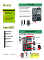
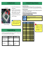
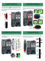
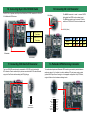
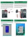
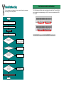
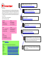
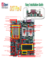
PS/2 Mouse
Connector
SPP/EPP/ECP Parallel Port
Speaker Out
RJ45 10/100
LAN Jack
(Optional)
FAN3 Connector
PS/2 Keyboard USB Port
Connector
COM 1 Port
COM 2 Port
Line-In MIC-In
AUX-IN Connector
CD-IN Connector
FAN2 Connector
Intel 82550 10/100 LAN
Controller
1500μF Low ESR Capacitors
CPU1 FAN connector
CPU2 FAN Connector
AGP Pro Slot
USB Connector
Dual CPU sockets
CPU #2
CPU #1
FAN1 Connector
32 Bit PCI Slot x 5
4Mbit Flash BIOS
Game Port Connector
ATX 20-pin Power Connector
AGP Pro Power Connector
VIA Pro266T Chipset
Dual Channel Ultra 160 SCSI
Connector
Adaptec 7899W SCSI
Controller
WOL (Wake on LAN) Connector
184-pin DIMM Socket x4 supports
PC-1600/2100 DDR SDRAM
maximum up to 2 GB
JP14 CMOS Clear Jumper
Redundant SPS Connector
ATA/33/66/100 IDE Connector x2
FDD Connector
Front Panel Connector
SCSI LED Connector
1. JP14 Clear CMOS
You can clear CMOS to restore system default setting. To
clear the CMOS, follow the procedure below.
1. Turn off the system and unplug the AC power.
Everything you need to boot this
motherboard is included in this
Easy Installation Guide. For more
information, a complete Online
User's Manual can be found in the
Bonus Pack CD Disc. Thanks for
the help of saving our earth.
2. Remove ATX power cable from connector PWR2.
3. Locate JP14 and short pins 2-3 for a few s econds.
4. Return JP14 to its normal setting by shorting pin 1 & pin 2.
5. Connect ATX power cable back to connector PWR2.
1
Normal
(default)
Floppy Drive Cable x 1
Clear CMOS
2. Installing CPU & System Fan
Hard Drive IDE Cable x 1
80-Wire IDE Cable x 1
1
Plug in the CPU fan cable to the 3-pin CPU1 FAN and CPU2 FAN connector. If you have chassis fan, you
can also plug it on System FAN (FAN2) or AUX FAN (FAN3) connector.
Ultra 160 SCSI 68 pin Cable x 1
FAN3 Connector
Bonus Pack CD disc x 1
User Manual x 1
This Easy Installation Guide x 1
FAN2
Connector
I/O Bracket x 1
ASM Lite x 1
CPU1 Fan Connector
SCSI Utility Driver x 1
SENSOR
PART NO: 90.53G30.002
DOC. NO: D X37PU-EG-E0110A
GND
+12V
SENSOR
FAN1 Connector
+12V
Note: Some CPU fans do not have
sensor pin so they cannot support fan
monitoring.
GND
3. Installing Processor
5. Setting CPU Voltage & Frequency
1.
Pull up the CPU socket level and up to
90-degree angle.
Setting CPU Core Voltage
This motherboard supports CPU VID function. The CPU core voltage will be automatically
detected and the range is from 1.05V to 1.825V. It is not necessary to set CPU Core Voltage
2.
Locate Pin 1 in the socket and look for a
(golden) cut edge on the CPU upper
interface. Match Pin 1 and cut edge.
Then insert the CPU into the socket.
3.
Press down the CPU socket level and
finish CPU installation.
CPU socket lever
Note: If you do not match the CPU
socket Pin 1 and CPU cut edge
well, it may damage the CPU.
CPU Pin 1 and cut edge
4. Supported CPU Type
The DX37 Plus-U supports Intel® Socket 370 Pentium III series CPU. Including the code
name Tualatin 512K cache CPU for dual CPU configuration.
Processor Name
Single Processor
Dual Processor
CPU Package
PentiumII
All
Pentium !!!
All
Pentium II
All
Pentium !!!
Coppermine
Pentium !!! 512K
Tualatin
Setting CPU Frequency
This motherboard is CPU jumper-less design, you can set CPU frequency through the BIOS
setup, no jumpers or switches are needed.
BIOS Setup > Frequency / Voltage Control > CPU Speed Setup
Core Frequency = CPU FSB Clock * CPU Ratio
CPU Ratio
3x, 3.5x, 4x, 4.5x, 5x, 5.5x, 6x, 6.5x, 7x, 7.5x, 8x, 8.5x, 9x, 9.5x, 10x, 10.5x, 11x, 11.5x,
12x, 12.5x, 13x, 13.5x, 14x, 14.5x, 15x, 15.5x and 16x
CPU FSB
(By BIOS Table)
100 and 133 MHz
CPU
CPU Core Frequency
FSB Clock
Pentium III 600E
600MHz
100MHz
6x
Pentium III 650E
650MHz
100MHz
6.5x
Pentium III 700E
700MHz
100MHz
7x
Pentium III 750E
750MHz
100MHz
7.5
Pentium III 800E
800MHz
100MHz
8x
Pentium III 850E
850MHz
100MHz
8.5x
Pentium III 533EB
533MHz
133MHz
4x
Pentium III 600EB
600MHz
133MHz
4.5x
Pentium III 667EB
667MHz
133MHz
5x
Pentium III 733EB
733MHz
133MHz
5.5
Pentium III 800EB
800MHz
133MHz
6x
Pentium III 866EB
866MHz
133MHz
6.5
Pentium III 933EB
933MHz
133MHz
7x
1GHz
133MHz
7.5x
Pentium III 1.13G
1.13GHz
133MHz
8.5x
Pentium III 1.26G
1.26GHz
133MHz
9x
Pentium III 1G
Ratio
Warning: We strongly
recommend you do not
overclocking your CPU
and system for get more
system reliability.
6. Support Four USB Connectors
8. Connecting IDE and Floppy Cables
This motherboard provides four USB connectors to connect USB devices, such as
mouse, keyboard, modem, printer, etc. There are two connectors on the PC99 back
panel. You can use proper cable to connect other USB connectors to the back panel or
front panel of chassis.
Connect 34-pin floppy cable and 40-pin, 80-wire IDE cable to floppy connector FDC and
IDE connector. Be careful of the pin1 orientation. Wrong orientation may cause system
damage.
Primary
Slave (2nd)
Primary
Master (1st)
Pin 1
IDE 1 (Primary)
IDE 2 (Secondary)
Pin 1
USB2 Connector
NC
GND
SBD3+
SBD3+5V
Secondary
Master (3rd)
Secondary
Slave (4th)
KEY
GND
SBD2+
SBD2+5V
ATA 33/66/100
IDE Connector
1
7. Connecting ATX and AGP Pro Power Connector
The DX37Plus-U uses standard ATX power connector. The 6-pin AGP Pro Power
connector provides extra +5V and +3.3V power for AGP Pro VGA card. Make sure you
plug in the right direction.
-5V
COM
COM
COM
PS-ON
COM
-12V
+3.3V
COM
+3.3V
+3.3V
6
+5V
+3.3V
+3.3V
1
GND
GND
GND
FDD Connector
9. Connecting Front Panel Cable
Attaching such as power LED, speaker, reset switch, power switch connector, etc.… to
corresponding pins. The green cap on pin 19 & 20 is to disable Chassis Intrusion
Switch, you may just take it off to able this function.
21 22
+5V
+12V
5VSB
PW-OK
COM
+5V
COM
+5V
Pin 1
Chassis Intrusion
Switch
Reset Switch
HDD LED
Power LED
ATX Power
Switch
Pin 1
1 2
21 22
GND
GND
INT S/W
RST S/W
+5V
HDD LED
HDD LED
+5V
+5V
GND
PWR LED
GND
+5VSB
1
2
10. Connecting 68-pin Ultra 160 SCSI Cable
The DX37Plus-U provides two 68-pin Ultra )
Wide/Ultra 2/3 SCSI connectors for 16-bit or
16-bit differential SCSI devices.
12. Connecting CD / AUX Connector
The AUX-IN connector is used to connect MPEG
Audio cable from MPEG card to onboard sound.
The CD-IN connector is used to connect CD Audio
cable from CDROM or DVD drive to onboard sound.
CD- IN (Black)
AUX-IN (Green)
SW1(3)
On
Disable SCSI Ch A
Terminator
SW1(4)
On
Disable SCSI Ch B
Terminator
Connector
Pin1
Pin2
Pin3
Pin4
AUX-IN
Left
GND
GND
Right
Left
GND
GND
Low ESR
capacitor
Right
CD-IN
A Terminator
B Terminator
11. Connecting SCSI Card LED Connector
The 4-pin SCSI LED connector can be connected to a PCI SCSI control card activity
LED connector. Read or write activity by devices connected to the SCSI card will transfer
a signal to Front Panel and thus making the LED lighting up.
13. Redundant SPS Monitoring Connector
This motherboard implements Redundant SPS monitoring connector to provide hardware
monitoring signals . It is feasible to install an additional 337-watt power supply module
(optional with AOpen Server Housing) in a hot swappable configuration. If any SPS failed,
a signal will be sent to a hardware monitoring device.
14
+
+
SCSI Card
LED Connector
13
Fan 3 Fail
PS 3 Fail
PS ON
Present1
I2C CLK
Fan 1 Fail
PS1 Fail
+12V
Present 3
GND
5VSB
Present 2
Fan 2 Fail
PS 2 Fail
2
1
16. Wake On LAN
14. Support 10/100 Mbps LAN onboard
The South Bridge V8233 of VIA Apollo Pro266T chipset includes a fast Ethernet controller on
chip. On the strength of Intel 82550 PHY on board, which is a highly-integrated Platform LAN
Connect device, it provides 10/100M bps Ethernet for office and home use, the Ethernet RJ45
connector is located on the back panel. The green LED indicates the link mode, it lights when
linking to network and blinking when transferring data. The orange LED indicates the transfer
mode, and it lights when data is transferring in 100Mbps mode. To enable or disable this
function, you may simply adjust it through BIOS.
To use Wake On LAN function, you must have a network card with chipset that supports this
feature, and connect a cable from LAN card to motherboard WOL connector. The system
identification information (probably IP address) is stored on network card and because there is
a lot of traffic on the Ethernet, you need to install a network management software, such as
ADM, for the checking of how to wake up the system. Note that, at least 600mA ATX standby
current is required to support the LAN card for this function.
Green/ACT
Orange/Speed
+5VSB
GND
LID
15. Power-On and Load BIOS Setup
17. Installing Onboard Sound Driver
After you finish the setting of jumpers and connect correct cables. Power on and enter the
BIOS Setup, press <Del> during POST (Power On Self Test). Choose "Load Default
Setting" for recommended optimal performance.
This motherboard comes with an AD 1885 AC97 CODEC, you can find the audio driver
from the Bonus Pack CD disc auto-run menu.
Del
Part Number and Serial Number
If you encounter any trouble to boot you system, follow the procedures
accordingly to resolve the problem.
The Part Number and Serial number are printed on bar code label. You can find this
bar code label on the outside packing, on ISA/CPU slot or on component side of PCB.
For example:
Start
Turn off the power and unplug the AC power cable, then remove all
of the addon cards and cables, including VGA, IDE, FDD, COM1,
COM2 and Printer.
Part No.
Serial No.
Make sure if the jumper settings for CPU and DRAMs are correct.
Clear CMOS.
Part No.
Install the VGA card. Then connect your monitor and keyboard.
Turn on the power, and check if
the power supply and CPU fan
work properly.
P/N: 91.88110.201 is part number, S/N: 91949378KN73 is serial num ber.
No
The problem was probably caused
by power supply or motherboard
failure. Please contact your reseller
or local distributor for repairing.
Yes
No
Check if there is display.
Perhaps your VGA card or monitor
is defective.
Yes
Press Ctrl, and Alt key at the
same time, hold them and then
press Del to see if the
system reboots.
No
It is very possible that your keyboard
is defective.
Yes
During system rebooting, press Del to enter BIOS Setup. Choose
“Load Setup Default".
Turn off the system and
re- connect the IDE cable.
Check if the system can
reboot successfully.
Yes
Re- install Windows 95, Windows 98 or Windows NT.
End
Serial No.
No
The problem should be caused by the
IDE cables or HDD itself.
1
Online Manual: Please check the manual carefully and make sure the
jumper s ettings and installation procedure are correct.
http://www.aopen.com.tw/tech/download/manual/default.htm
Dear Customer,
2
Thanks for choosing AOpen products. To provide the best and fastest service to
our customer is our first priority. However, we receive numerous emails and
phone-calls worldwide everyday, it is very hard for us to serve everyone on time.
We recommend you follow the procedures below and seek help before contact
us. With your help, we can then continue to provide the best quality service to
more customers.
Thanks very much for your understanding!
AOpen Technical Supporting Team
Pacific Rim
AOpen Inc.
Tel: 886-2-2696-1333
Fax: 886-2-8691-2233
Europe
AOpen Computer b.v.
Tel: 31-73-645-9516
Fax: 31-73-645-9604
China
艾? ? ? ? 上海(股)有限公司
Tel: 49-2102-157700
Fax: 49-2102-157799
Germany
AOpen Computer GmbH.
Tel: 49-2102-157700
Fax: 49-2102-157799
3
Test Report: We recommend to choose board/card/device from the
compatibility test reports for assembling your PC.
http://www.aopen.com.tw/tech/report/default.htm
FAQ: The latest FAQ (Frequently Asked Questions) may contain a
solution to your problem.
http://www.aopen.com.tw/tech/faq/default.htm
Download Software: Check out this table to get the latest updated
BIOS/utility and drivers.
http://www.aopen.com.tw/tech/download/default.htm
4
5
News Group: Your problem probably had been answered by our support
engineer or professional users on the news group.
http://www.aopen.com.tw/tech/newsgrp/default.htm
America
AOpen America Inc.
Tel: 1-510-498-8928
Fax: 1-408-922-2935, 1-408-432-0496
6
Contact Distributors/Resellers: We sell our products through resellers
and integrators. They should know your system configuration very well and
should be able to solve your problem more efficien n important reference for
you if next time you want to buy something else from them.
Web Site: www.aopen.com
E-mail: Send us email by going through the contact form below.
English
http://www.aopen.com.tw/tech/contact/techusa.htm
Japanese
http://aojp.aopen.com.tw/tech/contact/techjp.htm
Chinese
http://w3.aopen.com.tw/tech/contact/techtw.htm
German
http://www.aopencom.de/tech/contact/techde.htm
French
http://aofr.aopen.com.tw/tech/contact/techfr.htm
Simplified Chinese
http://www.aopen.com.cn/tech/contact/techcn.htm
7
Contact Us: Please prepare detail system configuration and error symptom
before contacting us. The part number, serial number and BIOS version
are also very helpful.