1
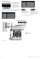
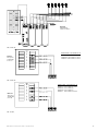
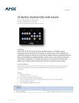
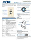
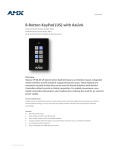
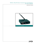
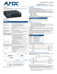
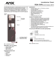
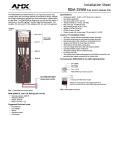
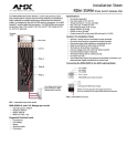
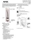
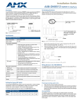
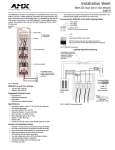
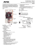
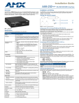
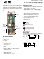
Installation Sheet
RDC-PDC Control Card, Dual or Three Phase
(120 or 240 VAC)
The RDC-PDC Control Card module controls up to six dimmable channels
with six satellite connectors (for RDM series dimmer or switching modules).
The RDC-PDC is controlled by AXlink, PROlink, or by dry contact closures.
The RDC-PDC is designed for use with Radia enclosures, in a modular digital dimming system. The module's 120 and 240 VAC ratings are CE, UL,
and C-UL approved.
Mounting
points
Button/Jumper Information:
•
RESET button: By pressing the RESET button, located on the RDCPDC circuit board, it is possible to restart the processor without having
to power-down the unit or disconnect AXlink or PROlink. RESET does
not affect saved presets or curve settings.
• MEMORY PROTECT on/off jumper: The MEMORY PROTECT
jumper is set to Off by default. To protect saved curve settings and presets from accidental recording, put the jumper in the On position.
Caution: Pre-Installation Notes
Line inputs
(factory wired)
•
•
•
•
•
•
•
•
•
•
All Class 1 wiring must be connected to proper terminals.
All control wiring must be connected to proper terminals.
Disconnect power while installing or connecting the unit.
Keep the top and bottom air vents clear at all times.
Test loads for shorts before connecting.
Use low-voltage wires with a 300 volt rating or greater.
Use field-installed copper conductors.
All electrical ratings are for continuous duty.
For indoor use only.
AC lighting loads only.
Connecting RDM Series to the AMX Lighting Master
AXlink DIP
switch
PROlink DIP
switch
Pin 4 (GND)
Pin 3 (RLY)
Pin 2 (DIM)
Pin 1 (+12 V)
RDC-PDC 4-pin module connector
Reset button
Memory Protect
jumper
4-pin plug from a RDM series module
Note: The 4-pin plugs from the module
connector to the 4-pin connector on the
master (black plug cover facing up).
AXlink connector
LED indicators
Dry closure
contacts
PROlink connector
FIG. 2 Connecting RDM series
Connecting AXlink
Control ports
Connect the 4-pin captive-wire AXlink connector from the RDC-PDC to the
Central Controller for AXlink control of the dimming system.
FIG. 1 RDC-PDC control card
PWR
RDC-PDC UL and C-UL Ratings:
AXP
AXM
GND
Control Input:
• AXlink
• PROlink
• Eight dry closures
Control Output:
• Six control ports
• Max. total control current at 300 mA
Power Inputs:
• Line 1 (channel 1 and 4)
• Line 2 A (channel 5)
• Line 2B (channel 2)
• Line 3 (channel 3 and 6)
• Neutral
Specifications:
•
•
•
•
•
•
•
Dimensions (HW): 10.0" x 2.75" (254.0 mm x 69.85 mm)
12 VDC power (optional)
Torque terminals to 20 in-lbs. (2.3 N/M)
Max. wire size: 10 AWG
Wire stripping length: 0.28" (7 mm)
Weight: 1.5 lbs. (0.68 kg)
Power consumption: 50 mA @ 120 VAC
25 mA @ 240 VAC
RDC-PDC
(optional)
PWR
AXP
AXM
GND
Central
Controller
FIG. 3 AXlink wiring
Connecting PROlink:
Connect the orange 4-pin captive-wire PROlink connector from the RDCPDC to a PRO-DP8 PROlink wall panel.
PRO-DP8
Pack 1
Pack 2
+12
+12
PR+
PR-
PR+
PR-
GND
GND
FIG. 4 PROlink wiring
Connecting Dry Closures
Dry Closure Default Presets (Cont.)
Use the 8 (+ common) dry closures with a WPD8 eight-button wall panel.
1
2
3
4
5
6
7 8 COM
Each contact (1 - 8) is preprogrammed with a default preset.
Refer to the AMX Lighting Control
System instruction manual for
details on dry closure default presets
and recording new presets.
5
Channel 5 at 100% in 1 second
6
Channel 6 at 100% in 1 second
7
Pack on (channels 1-6)
8
Pack off (channels 1-6
All other channels are undefined.
Setting AXlink and PROlink Address Numbers:
AXlink Address
PROlink Address
FIG. 5 Dry closures connection
Test
Each contact closure connection (1 - 8) is pre-programmed with a default
preset. The table below shows the default presets for each contact closure.
Dry Closure Default Presets
Contact Closure
Set the AXlink address number
(1-255) for the RDC-DC. This
number must match the device
number in your Axcess program.
Default Function
1
Channel 1 at 100% in 1 second
2
Channel 2 at 100% in 1 second
3
Channel 3 at 100% in 1 second
4
Channel 4 at 100% in 1 second
Use the PROlink DIP switch to set
the PROlink address number for the
RDC-DC (1-10).
Pin 8 on the PROlink DIP switch is
a test switch that turns all circuits on
to full.
FIG. 6 Setting AXlink and PROlink address numbers.
Lighting Application Drawings
Method A
RDC-PDC/120, 3 Phase
6 dimmers, 0 switches
FIG. 7 Method A
2
RDC-PDC Control Card, Dual or Three Phase
Method B
RDC-PDC/120
3-phase, 6 switches
FIG. 8 Method B
THREE PHASE, 120/208 VAC, 4W + G
Method C
Three phase,
120/208 VAC,
4 wire + G
PHASE A - Controls Dimmers 1 and 4
PHASE B - Controls Dimmers 2 and 5
PHASE C - Controls Dimmers 3 and 6
FIG. 9 Method C
THREE PHASE, 120/208 VAC, 5W + G
PHASE A - Controls Dimmers 1 and 4
PHASE B1 - Controls Dimmer 5
PHASE B2 - Controls Dimmer 2
PHASE C - Controls Dimmers 3 and 6
Method D
Three phase,
120/208 VAC
5 wire +G
FIG. 10 Method D
RDC-PDC Control Card, Dual or Three Phase
3
AMX Corporation reserves the right to alter specifications without notice at any time.
For full warranty information, refer to the AMX Instruction Manual(s) associated with your Product(s).
043-019-2193 8/01 ©2001 AMX Corporation. All rights reserved.
The AMX logo is a trademark of AMX Corporation. AMX Corporation reserves the right to alter specifications without notice at any time.
3000 research drive, richardson, TX 75082 USA • 469.624.8000 • 800.222.0193 • fax 469.624.7153 • technical support 800.932.6993