1
Hardware Reference Guide
NI-x100 Series
NetLinx® Integrated Controllers
(NI-2100, NI-3100, NI-4100)
NetLinx Integrated Controllers
L a s t R e v i s e d : 1 /9 / 2 0 0 9
AMX Limited Warranty and Disclaimer
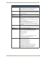
AMX warrants its products to be free of defects in material and workmanship under normal use for three (3) years from
the date of purchase from AMX, with the following exceptions:
•
Electroluminescent and LCD Control Panels are warranted for three (3) years, except for the display and touch
overlay components that are warranted for a period of one (1) year.
•
Disk drive mechanisms, pan/tilt heads, power supplies, and MX Series products are warranted for a period of one
(1) year.
•
AMX Lighting products are guaranteed to switch on and off any load that is properly connected to our lighting
products, as long as the AMX Lighting products are under warranty. AMX does guarantee the control of dimmable
loads that are properly connected to our lighting products. The dimming performance or quality cannot be
guaranteed due to the random combinations of dimmers, lamps and ballasts or transformers.
•
Unless otherwise specified, OEM and custom products are warranted for a period of one (1) year.
•
AMX Software is warranted for a period of ninety (90) days.
•
Batteries and incandescent lamps are not covered under the warranty.
This warranty extends only to products purchased directly from AMX or an Authorized AMX Dealer.
All products returned to AMX require a Return Material Authorization (RMA) number. The RMA number is obtained
from the AMX RMA Department. The RMA number must be clearly marked on the outside of each box. The RMA is
valid for a 30-day period. After the 30-day period the RMA will be cancelled. Any shipments received not consistent
with the RMA, or after the RMA is cancelled, will be refused. AMX is not responsible for products returned without a
valid RMA number.
AMX is not liable for any damages caused by its products or for the failure of its products to perform. This includes any
lost profits, lost savings, incidental damages, or consequential damages. AMX is not liable for any claim made by a
third party or by an AMX Dealer for a third party.
This limitation of liability applies whether damages are sought, or a claim is made, under this warranty or as a tort claim
(including negligence and strict product liability), a contract claim, or any other claim. This limitation of liability cannot
be waived or amended by any person. This limitation of liability will be effective even if AMX or an authorized
representative of AMX has been advised of the possibility of any such damages. This limitation of liability, however, will
not apply to claims for personal injury.
Some states do not allow a limitation of how long an implied warranty last. Some states do not allow the limitation or
exclusion of incidental or consequential damages for consumer products. In such states, the limitation or exclusion of
the Limited Warranty may not apply. This Limited Warranty gives the owner specific legal rights. The owner may also
have other rights that vary from state to state. The owner is advised to consult applicable state laws for full
determination of rights.
EXCEPT AS EXPRESSLY SET FORTH IN THIS WARRANTY, AMX MAKES NO OTHER WARRANTIES,
EXPRESSED OR IMPLIED, INCLUDING ANY IMPLIED WARRANTIES OF MERCHANTABILITY OR FITNESS FOR
A PARTICULAR PURPOSE. AMX EXPRESSLY DISCLAIMS ALL WARRANTIES NOT STATED IN THIS LIMITED
WARRANTY. ANY IMPLIED WARRANTIES THAT MAY BE IMPOSED BY LAW ARE LIMITED TO THE TERMS OF
THIS LIMITED WARRANTY.
Table of Contents
Table of Contents
Introduction ........................................................................................................1
NI-2100 Specifications .............................................................................................. 2
NI-3100 Specifications .............................................................................................. 5
NI-4100 Specifications .............................................................................................. 8
Related Documents................................................................................................. 11
Installation and Upgrading ...............................................................................13
Installing NetLinx Control Cards (NI-4100 Only) ..................................................... 13
Setting the NetLinx Control Card Addresses (NI-4100 Only).................................. 14
Device:Port:System (D:P:S)............................................................................................ 14
Removing NetLinx Control Cards (NI-4100 Only) ................................................... 15
Compact Flash Upgrades ........................................................................................ 15
Accessing The Internal Components On An Integrated Controller ............................... 15
Installation of Compact Flash Upgrades........................................................................ 16
Closing and Securing the Outer Housing ...................................................................... 17
Installing Into An Equipment Rack .......................................................................... 17
Connections and Wiring ...................................................................................19
Setting the Configuration DIP Switch (for the Program Port) ................................. 19
Baud Rate Settings........................................................................................................ 19
Program Run Disable (PRD) Mode................................................................................. 19
Working With the Configuration DIP Switch ................................................................. 20
Setting the CardFrame DIP Switch (NI-4100 Only) ................................................. 20
Program Port Connections and Wiring ................................................................... 20
Modes and Front Panel LED Blink Patterns ............................................................ 21
Port Assignments and Functionality........................................................................ 21
AXlink Port and LED ............................................................................................... 22
Wiring Guidelines ................................................................................................... 22
Wiring length guidelines ............................................................................................... 22
Preparing Captive Wires ............................................................................................... 23
Wiring a Power Connection........................................................................................... 23
Using the 4-Pin Mini-Phoenix Connector For Data and Power ...................................... 23
Using the 4-pin Mini-Phoenix Connector For Data With External Power ...................... 24
DB9 Device Port: Connections and Wiring ............................................................. 24
ICSNet Port: Connections and Wiring..................................................................... 25
ICSHub OUT Port: Connections and Wiring ............................................................ 26
Relay Port: Connections and Wiring ....................................................................... 26
Relay Connections ......................................................................................................... 26
NI-2100, NI-3100, NI-4100 Hardware Reference Guide
i
Table of Contents
Input/Output (I/O) Port: Connections and Wiring ................................................... 27
IR/Serial Port: Connections and Wiring................................................................... 28
NetLinx Control Card Slot Connector (NI-4100 only).............................................. 28
Ethernet/RJ-45 Port: Connections and Wiring ........................................................ 29
Ethernet LEDs .............................................................................................................. 29
Ethernet Ports Used By the Integrated Controller ........................................................ 30
ii
NI-2100, NI-3100, NI-4100 Hardware Reference Guide
Introduction
Introduction
The X100-Series of NetLinx Integrated Master Controllers can both be programmed to control
RS-232/422/485, Relay, IR/Serial, and Input/Output devices through the use of both the NetLinx
programming language and the NetLinx Studio application version 2.x. Another key feature of this
products is the ability to easily access the configuration switches without having to remove a cover plate.
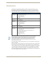
NetLinx Integrated Master Controller Features
NI-2100
(FG2105-04)
• 1 RS-232 Program port
• 3 RS-232/RS-422/RS-485 ports
• 4 IR/Serial Output ports
• 4 Digital Input/Output ports
• 4 Relays
NI-2100 Kit
(FG2105-14)
• In addition to the options listed above, this Kit includes a pre-installed ICSNet daughter
card (FG2105-10)
NI-3100
(FG2105-05)
• 1 RS-232 Program port
• 7 RS-232/RS-422/RS-485 ports
• 8 IR/Serial Output ports
• 8 Digital Input/Output ports
• 8 Relays
NI-3100 Kit
(FG2105-15)
• In addition to the options listed above, this Kit includes a pre-installed ICSNet daughter
card (FG2105-10)
NI-4100
(FG2105-06)
• Support for up to 4 NetLinx control cards (such as NXC-COM2, NXC-IRS4, etc.)
• 1 ICSNet Hub port (part of the included pre-installed ICSNet card)
• 1 RS-232 Program port
• 2 ICSNet ports (part of the included pre-installed ICSNet card)
• 7 RS-232/RS-422/RS-485 ports
• 8 IR/Serial Output ports
• 8 Digital Input/Output ports
• 8 Relays
References within this manual to NI X100-Series Controllers are used to describe the
NI-2100/3100/4100 Integrated Controllers. When there is an overlap of information
with other related NI Controllers, an X will be used to refer to both sets of units.
As an example, if a feature is shared by both the NI-4000 and the NI-4100 Controller,
the term NI-4x00 Series is used.
These NI Controllers are shipped with Duet firmware and can not be downgraded to earlier Non-Duet
firmware (< build 300).
These NI Controllers are Duet-compatible and can be upgraded via firmware. Duet is a dual-interpreter
firmware platform from AMX which combines the proven reliability and power of NetLinx with the
extensive capabilities of the Java®2 MicroEdition (J2ME) platform. Duet simplifies the programming of
a system that includes the NI-900 and other third party devices by standardizing device and function
definitions, defaulting touch panel button assignments, and controlling feedback methods. Dynamic
Device Discovery makes integration even easier by automatically identifying and communicating with
devices which support this new beaconing technology.
NI-2100, NI-3100, NI-4100 Hardware Reference Guide
1
Introduction
These NI Controllers use a combination lithium battery and clock crystal package called a Timekeeper.
Only one Timekeeper unit is installed within a given NI controller. The battery can be expected to have
up to 3 years of usable life under very adverse conditions. Actual life is appreciably longer under normal
operating conditions.
This calculation is based on storing the unit without power in 50° C (120° F) temperature until
battery levels are no longer acceptable.
The part number for a replacement battery is 57-0032.
NI-2100 Specifications
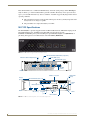
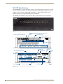
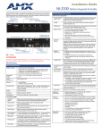
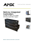
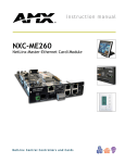
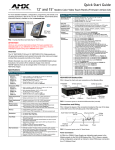
The NI-2100 (FIG. 1) provides support for 3 RS-232/RS-422/RS-485 Ports, 4 IR/Serial Output ports, 4
Digital Input/Output ports, and 4 Relays. The NI-2100 can be upgraded to provide
1 ICSHub and 2 ICSNet ports by either installing the optional ICSNet daughter card (FG2105-10) or
purchasing this upgrade as an included feature of the NI-2100 Kit (FG2105-14).
FIG. 1 NI-2100 NetLinx Integrated Controller (front view)
RS-232/422/485 TX/RX LEDs (red/yellow)
Link/Active-Status-Output-Input
Relay LEDs (red)
IR/Serial LEDs (red)
LINK/ACT
STATUS
INPUT
OUTPUT
1
2
3
1
TX RX TX RX TX RX
RS - 232 / 422 / 485
2
3
4
1
RELAYS
2
3
4
1
IR / SERIAL
2
3
4
I/O
I/O LEDs
(yellow)
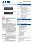
Front
AXlink LED
(green)
ICSNet cover plate
Relays
(Port 4)
RS-232/422/485 (Ports 1-3)
PORT 3
PORT 2
PORT 1
Ethernet
IR/Serial (Ports 5-8)
Pin
1
2
3
4
5
Rear
I/O (Port 9)
RS - 232 / 422 / 485
(Ports 1-3)
Function Pin Function
RXRXD
TXD
TX+
GND
6
7
8
9
RX+
RTS
CTS
TX-
DIP
switch
Program
port
AXlink
port
ETHERNET
10 / 100
L/A
SPD
PWR
ID Pushbutton
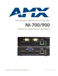
FIG. 2 NI-2100 front and rear panel connectors and components
2
NI-2100, NI-3100, NI-4100 Hardware Reference Guide
Introduction
NI-2100 Specifications
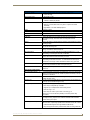
Dimensions (HWD):
• 3.47" x 17.00" x 3.47" (8.81 cm x 43.18 cm x 8.82 cm)
• 2 rack units high
Power Requirement:
700 mA @ 12 VDC
Memory:
• 64 MB SDRAM
Compact Flash:
128 MB or more - Upgradeable (see Other AMX Equipment)
• 1 MB Non-volatile (NV) SRAM
Note: AMX may increase Flash size at any time in response to
market availability (refer to product’s online catalog page for current Compact
Flash size provided).
Weight:
4.50 lbs (2.04 kg)
Enclosure:
Metal with black matte finish
Certifications:
FCC Part 15 Class B, CE, and IEC 60950
Front Panel LEDs:
• LINK/ACT:
Green LED blinks when the Ethernet cables are connected and
terminated correctly. Also blinks when receiving Ethernet data
packets.
• Status:
Green LED blinks to indicate that the system is programmed and communicating properly.
• Output:
Red LED blinks when the Controller transmits data, sets channels On and
Off, sends data strings, etc.
• Input:
Yellow LED blinks when the Controller receives data from button pushes,
strings, commands, channel levels, etc.
• RS-232/422/485:
3 sets of red and yellow LEDs light to indicate that DB9 Ports 1 - 3 are transmitting or receiving RS-232, 422, or 485 data.
• Relay:
4 red LEDs light to indicate the relay channels 1 - 4 are active (closed).
These LEDs reflect the state of the relay on Port 4.
• IR/Serial:
4 red LEDs light to indicate the IR/Serial channels 1 - 4 are
transmitting control data on Ports 5 - 8. LED indictor for each IR port remains
lit for the length of time that IR/Serial data is being generated.
• I/O:
4 yellow LEDs light when the I/O channels 1 - 4 are active. The LED for each
I/O port reflects the state of that particular port.
Rear Panel Components:
• RS-232/422/485 (Ports 1 - 3): 3 RS-232/422/485 control ports using DB9 (male) connectors with XON/
XOFF (transmit on/transmit off), CTS/RTS (clear to send/ready to send), and
300-115,200 baud.
• ICSNet:
2 RJ-45 connectors for ICSNet interface (provided by optional
ICSNet daughter card).
• ICSHub Out:
RJ-45 connector provides data to a Hub connected to the Controller (provided by optional ICSNet daughter card).
• Relay (Port 4):
• Four-channel single-pole single-throw relay ports
• Each relay is independently controlled.
• Supports up to 4 independent external relay devices
• Channel range = 1-4
• Each relay can switch up to 24 VDC or 28 VAC @ 1 A
8-pin 3.5 mm mini-Phoenix (female) connector provides relay termination
• Digital I/O (Port 9):
4-channel binary I/O port for contact closure with each input being capable of
voltage sensing. Input format is software selectable with interactive power
sensing for IR ports.
NI-2100, NI-3100, NI-4100 Hardware Reference Guide
3
Introduction
NI-2100 Specifications (Cont.)
Rear Panel Components (Cont.):
• IR/Serial
(Ports 5 - 8):
4 IR/Serial control ports support high-frequency carriers of up to 1.142 MHz
with each output being capable of two electrical formats: IR or Serial.
• 4 IR/Serial data signals can be generated simultaneously.
• IR ports support data mode (at limited baud rates and wiring distances).
• Program Port:
RS-232 DB9 connector (male) can be connected to a DB9 port on a PC. This
connector can be used with serial and NetLinx programming commands, as
well as other DB9 capable devices, to both upload/download information from
the NetLinx Studio program.
• Configuration DIPSwitch:
Sets the communication parameters for the Program port (see Baud Rate
Settings).
• ID Pushbutton:
Sets the NetLinx ID (Device only) assignment for the device.
• Ethernet Port:
RJ-45 connector provides TCP/IP communication. This is an Auto MDI/MDIX enabled port, which allows you to use either straight-through or crossover
Ethernet cables.
The Ethernet Port LEDs show communication activity, connection status,
speeds, and mode information:
• SPD (speed) - Yellow LED lights On when the connection speed is 100
Mbps and turns Off when the speed is 10 Mbps.
• L/A (link/activity) - Green LED lights On when the Ethernet cables are
connected and terminated correctly, and blinks when receiving Ethernet
data packets.
• AxLink Port:
4-pin 3.5 mm mini-Phoenix (male) connector that provides data and power to
external control devices. Green AXlink LED indicates the state of the AXlink
port.
• Power Port:
2-pin 3.5 mm mini-Phoenix (male) connector.
Included Accessories:
• 2-pin 3.5 mm mini-Phoenix (female) PWR connector (41-5025)
• 4-pin 3.5 mm mini-Phoenix (female) AXlink connector (41-5047)
• 6-pin 3.5 mm mini-Phoenix female I/O connector (41-5063)
• 8-pin 3.5 mm mini-Phoenix female Relay connector (41-5083)
• Installation Kit (KA2105-01):
- 8-pin Relay Common Strip
- 4 rack mount screws
- 4 washers
• 2 CC-NIRC NetLinx IR Emitter Cables (FG10-000-11)
• 2 removable rack ears (62-2105-07)
Other AMX Equipment:
• 2-pin 3.5 mm mini-Phoenix male connector (41-5026)
• CSB Cable Support Bracket (FG517)
• CC-COM Programming Port Cable (FG10-727)
• CC-NSER IR/Serial cable (FG10-007-10)
• ICSNet daughter card (FG2105-10)
• NCK, NetLinx Connector Kit (FG2902)
• STS, Serial To Screw Terminal (FG959)
• Upgrade Compact Flash (factory programmed with firmware):
NXA-CF2NI256M - 256 MB compact flash card (FG2116-47)
NXA-CF2NI512M - 512 MB compact flash card (FG2116-48)
NXA-CF2NI1G - 1 GB compact flash card (FG2116-49)
4
NI-2100, NI-3100, NI-4100 Hardware Reference Guide
Introduction
NI-3100 Specifications
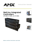
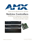
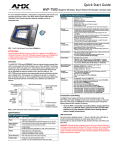
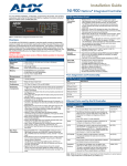
The NI-3100 (FIG. 3) provides support for 7 RS-232/RS-422/RS-485 Ports, 8 IR/Serial Output ports, 8
Digital Input/Output ports, and 8 Relays.
The NI-3100 can be upgraded to provide one ICSHub and two ICSNet ports by either installing the
optional ICSNet daughter card (FG2105-10) or purchasing this upgrade as an included feature of the NI3100 Kit (FG2105-15).
FIG. 3 NI-3100 NetLinx Integrated Controller (front view)
RS-232/422/485 TX/RX LEDs (red/yellow)
Relay LEDs (red)
IR/Serial LEDs (red)
Link/Active-Status-Output-Input
LINK/ACT
STATUS
INPUT
OUTPUT
1
2
3
4
5
6
7
TX RX TX RX TX RX TX RX TX RX TX RX TX RX
RS - 232 / 422 / 485
1
2
3
4
5
RELAYS
6
7
8
1
2
3
4
5
6
7
8
1
2
IR / SERIAL
3
4
5
6
7
8
I/O
I/O LEDs (yellow)
Front
AXlink LED
(green)
ICSNet cover plate
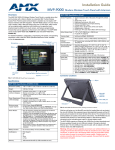
Rear
AXlink
port
RS-232/422/485 (Ports 1-7)
Ethernet
IR/Serial (Ports 9-16)
Pin
1
2
3
4
5
Relays
(Port 8)
I/O (Port 17)
Program
port
RS - 232 / 422 / 485
(Ports 1-7)
Function Pin Function
RXRXD
TXD
TX+
GND
6
7
8
9
DIP
switch
RX+
RTS
CTS
TX-
PWR
ID Pushbutton
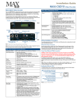
FIG. 4 NI-3100 front and rear panel connectors and components
NI-2100, NI-3100, NI-4100 Hardware Reference Guide
5
Introduction
NI-3100 Specifications
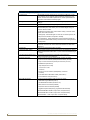
Dimensions (HWD):
• 3.47" x 17.00" x 3.47" (8.81 cm x 43.18 cm x 8.82 cm)
Power Requirement:
900 mA @ 12 VDC
Memory:
• 64 MB SDRAM
Compact Flash:
128 MB or more
• 2 rack units high
• 1 MB Non-volatile (NV) SRAM
• AMX may increase Flash size at any time in response to market availability
• Upgradeable - see Other AMX Equipment
Weight:
4.55 lbs (2.06 kg)
Enclosure:
Metal with black matte finish
Certifications:
FCC Part 15 Class B, CE, and IEC 60950
Front Panel LEDs:
• LINK/ACT:
Green LED blinks when the Ethernet cables are connected and
terminated correctly. Also blinks when receiving Ethernet data
packets.
• Status:
Green LED blinks to indicate that the system is programmed and communicating properly.
• Output:
Red LED blinks when the Controller transmits data, sets channels On and
Off, sends data strings, etc.
• Input:
Yellow LED blinks when the Controller receives data from button pushes,
strings, commands, channel levels, etc.
• RS-232/422/485:
7 sets of red and yellow LEDs light to indicate that DB9 Ports 1 - 7 are transmitting or receiving RS-232, 422, or 485 data.
• Relay:
• Eight-channel single-pole single-throw relay ports
• Each relay is independently controlled.
• Supports up to 8 independent external relay devices
• Channel range = 1-8
• Each relay can switch up to 24 VDC or 28 VAC @ 1 A
Two 8-pin 3.5 mm mini-Phoenix (female) connectors provide relay
termination
• IR/Serial:
8 red LEDs light to indicate the IR/Serial channels 1 - 8 are
transmitting control data on Ports 9 - 16. LED indictor for each IR port
remains lit for the length of time that IR/Serial data is being generated.
• I/O:
8 yellow LEDs light when the rear I/O channels 1 - 8 are active. The LED for
each I/O port reflects the state of that particular port.
Rear Panel Components:
• RS-232/422/485 (Ports 1 - 7): 7 RS-232/422/485 control ports using DB9 (male) connectors with XON/
XOFF (transmit on/transmit off), CTS/RTS (clear to send/ready to send), and
300-115,200 baud.
6
• ICSNet:
2 RJ-45 connectors for ICSNet interface (provided by optional
ICSNet daughter card).
• ICSHub Out:
RJ-45 connector provides data to a Hub connected to the Controller (provided by optional ICSNet daughter card).
• Relay (Port 8):
8-channel single-pole single throw relay ports with each relay being independently controlled and supporting up to 8 independent
external relay devices.
• Digital I/O (Port 17):
8-channel binary I/O port for contact closure with each input being capable of
voltage sensing. Input format is software selectable with interactive power
sensing for IR ports.
NI-2100, NI-3100, NI-4100 Hardware Reference Guide
Introduction
NI-3100 Specifications (Cont.)
Rear Panel Components (Cont.):
• IR/Serial (Ports 9 - 16):
8 IR/Serial control ports support high-frequency carriers of up to 1.142 MHz
with each output being capable of two electrical formats: IR or Serial.
• 8 IR/Serial data signals can be generated simultaneously.
• IR ports support data mode (at limited baud rates and wiring distances).
• Program Port:
RS-232 DB9 connector (male) can be connected to a DB9 port on a PC. This
connector can be used with serial and NetLinx programming commands, as
well as other DB9 capable devices, to both upload/download information from
the NetLinx Studio program.
• Configuration DIP
Switch:
Sets the communication parameters for the Program port (see Baud Rate
Settings).
• ID Pushbutton:
Sets the NetLinx ID (Device only) assignment for the device.
• Ethernet Port:
RJ-45 connector provides TCP/IP communication. This is an Auto MDI/MDI-X
enabled port, which allows you to use either straight-through or crossover
Ethernet cables.
The Ethernet Port LEDs show communication activity, connection status,
speeds, and mode information:
• SPD (speed) - Yellow LED lights On when the connection speed is 100
Mbps and turns Off when the speed is 10 Mbps.
• L/A (link/activity) - Green LED lights On when the Ethernet cables are
connected and terminated correctly, and blinks when receiving Ethernet
data packets.
• AxLink Port:
4-pin 3.5 mm mini-Phoenix (male) connector that provides data and power to
external control devices. Green AXlink LED indicates the state of the AXlink
port.
• Power Port:
2-pin 3.5 mm mini-Phoenix (male) connector.
Included Accessories:
• 2-pin 3.5 mm mini-Phoenix (female) PWR connector (41-5025)
• 4-pin 3.5 mm mini-Phoenix (female) AXlink connector (41-5047)
• 10-pin 3.5 mm mini-Phoenix (female) I/O connector (41-5107)
• Installation Kit (KA2105-01):
- 8-pin Relay Common Strip
- 4 rack mount screws
- 4 washers
• 2 8-pin 3.5 mm mini-Phoenix female Relay connectors (41-5083)
• 2 CC-NIRC NetLinx IR Emitter Cables (FG10-000-11)
• 2 removable rack ears (62-2105-07)
Other AMX Equipment:
• 2-pin 3.5 mm mini-Phoenix male connector (41-5026)
• CSB Cable Support Bracket (FG517)
• CC-NSER IR/Serial cables (FG10-007-10)
• ICSNet daughter card (FG2105-10)
• NCK, NetLinx Connector Kit (FG2902)
• STS, Serial To Screw Terminal (FG959)
• Upgrade Compact Flash (factory programmed with firmware):
NXA-CF2NI256M - 256 MB compact flash card (FG2116-47)
NXA-CF2NI512M - 512 MB compact flash card (FG2116-48)
NXA-CF2NI1G - 1 GB compact flash card (FG2116-49)
NI-2100, NI-3100, NI-4100 Hardware Reference Guide
7
Introduction
NI-4100 Specifications
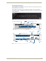
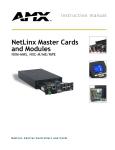
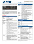
The NI-4100 (FIG. 5) is geared toward those advanced control and automation requirements associated
with most complex commercial and residential installations. The NI-4100 provides support for up to 4
NetLinx control cards (such as NXC-COM2, NXC-IRS4, etc.), 7 RS-232/RS-422/RS-485 Ports,
8 IR/Serial Output ports, 8 Digital Input/Output ports, and 8 Relays.
The NI-4100’s on-board Master also provides the ability to update installed control card firmware.
FIG. 5 NI-4100 NetLinx Integrated Controller (front view)
RS-232/422/485 TX/RX LEDs (red/yellow)
Relay LEDs (red)
Link/Active-Status-Output-Input
IR/Serial LEDs (red)
LINK/ACT
INPUT
OUTPUT
STATUS
1
2
3
4
5
6
7
TX RX TX RX TX RX TX RX TX RX TX RX TX RX
RS - 232 / 422 / 485
1
2
3
4
5
6
7
8
1
2
RELAYS
3
4
5
6
7
8
1
2
IR / SERIAL
3
4
5
6
7
8
I/O
I/O LEDs (yellow)
Front
NetLinx Card slots (1 - 4)
ICSNet (2)
RS-232/422/485 (Ports 1-7)
ICSHub Out
AXlink LED
(green)
AXlink
port
Rear
Relays
(Port 8)
IR/Serial
I/O
(Port 17) (Ports 9-16)
DIP
switch
Ethernet
Pin
1
2
3
4
5
RS - 232 / 422 / 485
(Ports 1-7)
Function Pin Function
RXRXD
TXD
TX+
GND
6
7
8
9
RX+
RTS
CTS
TX-
ID
Program port
ON
CardFrame DIP
switch
Slot 1-4 connectors
ID Pushbutton
PWR
FIG. 6 NI-4100 front and rear panel connectors and components
8
NI-2100, NI-3100, NI-4100 Hardware Reference Guide
Introduction
NI-4100 Specifications
Dimensions (HWD):
• 5.21" x 17.00" x 9.60" (13.23 cm x 43.18 cm x 24.27 cm)
• 3 rack units high
Power Requirement:
• 900 mA @ 12 VDC
Memory:
• 64 MB SDRAM
Compact Flash:
128 MB or more
• 1 MB Non-volatile (NV) SRAM
• AMX may increase Flash size at any time in response to market
availability
• Upgradeable - see Other AMX Equipment
Weight:
9.15 lbs (4.15 kg)
Enclosure:
Metal with black matte finish
Certifications:
FCC Part 15 Class B, CE, and IEC 60950
Front Panel LEDs/Slots:
• LINK/ACT:
Green LED blinks when the Ethernet cables are connected and
terminated correctly. Also blinks when receiving Ethernet data
packets.
• Status:
Green LED blinks to indicate that the system is programmed and communicating properly.
• Output:
Red LED blinks when the Controller transmits data, sets channels On and
Off, sends data strings, etc.
• Input:
Yellow LED blinks when the Controller receives data from button pushes,
strings, commands, channel levels, etc.
• RS-232/422/485:
7 sets of red and yellow LEDs light to indicate that DB9 Ports 1 - 7 are
transmitting or receiving RS-232, 422, or 485 data.
• Relay:
8 red LEDs light to indicate the relay channels 1 - 8 are active (closed).
These LEDs reflect the state of the relay on Port 8.
• IR/Serial:
8 red LEDs light to indicate the IR/Serial channels 1 - 8 are
transmitting control data on Ports 9 - 16. LED indictor for each IR port
remains lit for the length of time that IR/Serial data is being generated.
• I/O:
8 yellow LEDs light when the rear I/O channels 1 - 8 are active. The LED
for each I/O port reflects the state of that particular port.
• NetLinx Control Card Slots 1 - 4: Accepts up to 4 compatible NetLinx Cards: such as the NXC-COM2, NXCI/O10, etc.
Rear Panel Components:
• RS-232/422/485 (Ports 1 - 7):
7 RS-232/422/485 control ports using DB9 (male) connectors with XON/
XOFF (transmit on/transmit off), CTS/RTS (clear to send/ready to send),
and 300-115,200 baud.
• ICSNet:
2 RJ-45 connectors for ICSNet interface (provided by optional
ICSNet daughter card).
• ICSHub Out:
RJ-45 connector provides data to a Hub connected to the Controller (provided by optional ICSNet daughter card).
• Relay (Port 8):
• Eight-channel single-pole single throw relay ports
• Each relay is independently controlled.
• Supports up to 8 independent external relay devices
• Channel range = 1-8
• Each relay can switch up to 24 VDC or 28 VAC @ 1 A
Two 8-pin 3.5 mm mini-Phoenix (female) connectors provide relay
termination
• Digital I/O (Port 17):
8-channel binary I/O port for contact closure with each input being capable
of voltage sensing. Input format is software selectable with interactive
power sensing for IR ports.
• IR/Serial (Ports 9 - 16):
8 IR/Serial control ports support high-frequency carriers of up to 1.142
MHz with each output being capable of two electrical formats: IR or Serial.
• 8 IR/Serial data signals can be generated simultaneously.
• IR ports support data mode (at limited baud rates and wiring distances).
NI-2100, NI-3100, NI-4100 Hardware Reference Guide
9
Introduction
NI-4100 Specifications (Cont.)
Rear Panel Components (Cont.):
• Program Port:
RS-232 DB9 connector (male) can be connected to a DB9 port on a PC.
This connector can be used with serial and NetLinx programming commands, as well as other DB9 capable devices, to both upload/download
information from the NetLinx Studio program.
• Configuration DIPSwitch:
Sets the communication parameters for the Program port (see Baud Rate
Settings).
• ID Pushbutton:
Sets the NetLinx ID (Device only) assignment for the device.
• Ethernet Port:
RJ-45 connector provides TCP/IP communication. This is an Auto MDI/
MDI-X enabled port, which allows you to use either straight-through or
crossover Ethernet cables.
The Ethernet Port LEDs show communication activity, connection status,
speeds, and mode information:
• SPD (speed) - Yellow LED lights On when the connection speed is 100
Mbps and turns Off when the speed is 10 Mbps.
• L/A (link/activity) - Green LED lights On when the Ethernet cables are
connected and terminated correctly, and blinks when receiving Ethernet
data packets.
• AxLink Port:
4-pin 3.5 mm mini-Phoenix (male) connector that provides data and power
to external control devices. Green AXlink LED indicates the state of the
AXlink port.
• Power Port:
2-pin 3.5 mm mini-Phoenix (male) connector.
• CardFrame #DIP Switch:
Sets the starting address for the Control Cards in the CardFrame. (Factory
default CardFrame DIP switch value = 0). The Control Card address range
is 1-3064.
• Control Card Connectors (1-4):
20-pin (male) connectors that connect the Control Cards and
external equipment to the CardFrame.
Included Accessories:
• 2-pin 3.5 mm mini-Phoenix (female) PWR connector (41-5025)
• 4-pin 3.5 mm mini-Phoenix (female) AXlink connector (41-5047)
• 10-pin 3.5 mm mini-Phoenix (female) I/O connector (41-5107)
• Installation Kit (KA2105-01):
- 8-pin Relay Common Strip
- 4 rack mount screws
- 4 washers
• 2 8-pin 3.5 mm mini-Phoenix (female) Relay connectors
(41-5083)
• 2 CC-NIRC NetLinx IR Emitter Cables (FG10-000-11)
• 2 removable rack ears (62-2105-07)
Other AMX Equipment:
• 2-pin 3.5 mm mini-Phoenix male connector (41-5026)
• CSB Cable Support Bracket (FG517)
• CC-NSER IR/Serial cables (FG10-007-10)
• NCK, NetLinx Connector Kit (FG2902)
• STS, Serial To Screw Terminal (FG959)
• Upgrade Compact Flash (factory programmed with firmware):
NXA-CF2NI256M - 256 MB compact flash card (FG2116-47)
NXA-CF2NI512M - 512 MB compact flash card (FG2116-48)
NXA-CF2NI1G - 1 GB compact flash card (FG2116-49)
10
NI-2100, NI-3100, NI-4100 Hardware Reference Guide
Introduction
Related Documents
For information on using the on-board Web Console, as well as NetLinx send commands and terminal
communications to configure the NI Controllers, refer to the NetLinx Integrated Controller WebConsole
& Programming Guide.
All product documentation is available to view or download from www.amx.com.
NI-2100, NI-3100, NI-4100 Hardware Reference Guide
11
Introduction
12
NI-2100, NI-3100, NI-4100 Hardware Reference Guide
Installation and Upgrading
Installation and Upgrading
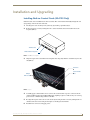
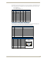
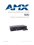
Installing NetLinx Control Cards (NI-4100 Only)
NetLinx Cards can be installed into the front card slots. The cards mount horizontally through the card
slot openings on the front of the enclosure.
1. Discharge the static electricity from your body, by touching a grounded object.
2. Remove the three screws by turning them in a counter-clockwise direction and then remove the
faceplate (FIG. 7).
Thumbscrews
NXC Card Slot faceplate
FIG. 7 NI-4100 front faceplate
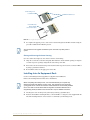
3. Align the edges of the card with the internal guide slots and gently slide the card all the way into the
slot (FIG. 8).
Card slots
Sample
NXC cards
Internal Guide
slots
FIG. 8 Sample NXC cards inserted into an NI-4100 unit
4. Carefully apply a small amount of force to insert the cards into their respective connectors. If the
cards have LEDs on them, those LEDs will initiate a lighting sequence to indicate they are receiving
power and are communicating with the Controller.
5. Re-align the faceplate and secure it to the chassis by inserting the three screws by turning them in a
clockwise direction and securing the front plate to the Integrated Controller.
6. Install all rear connectors and apply power.
NI-2100, NI-3100, NI-4100 Hardware Reference Guide
13
Installation and Upgrading
If the cards do not appear in the NetLinx Studio’s Workspace window for the selected
Master System number: give the system time to detect the inserted cards (and
refresh the system) and/or cycle power to the unit.
Setting the NetLinx Control Card Addresses (NI-4100 Only)
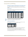
The 8-position CardFrame Number DIP switch (located on the rear of the NI-4100) sets the
starting address (the device number in the D:P:S specification) for the Control Cards installed
in the CardFrame. The address range is 1-3064.
The factory default CardFrame DIP switch value = 0 (all CardFrame DIP switches in the OFF
position).
The formula for setting the starting address is:
(DIP switch address x 12) + Card slot Number (1-12) = Card address
For example:
DIP switch setting, 00010101: (0 + 0 + 0 + 96 + 0 + 384 + 1536) + SLOT #(ex:1) = 2017.
A card in slot number 1 would be device address 2017.
1. Set the CardFrame Number DIP switch based on the information listed in the table below.
Position
1
2
3
4
5
6
7
8
Value
12
24
48
96
192
384
768
1536
ON position
2. Cycle power to the unit for approximately 5 seconds. This allows the unit to read the new device
number settings.
Device:Port:System (D:P:S)
A device is any hardware component that can be connected to an AXlink or ICSNet bus. Each device
must be assigned a unique number to locate that device on the bus. The NetLinx programming language
allows numbers in the range 1-32,767 for ICSNet (255 for AXlink).
Only the Device value can be set through the DIP switch settings mentioned above.
NetLinx requires a Device:Port:System (D:P:S) specification. This D:P:S triplet can be expressed as a
series of constants, variables separated by colons, or a DEV structure. For example:
STRUCTURE DEV
{
INTEGER Number
// Device number
INTEGER Port
// Port on device
INTEGER System
// System the device belongs to
}
The D:P:S notation is used to explicitly represent a device number, port and system.
For example, 128:1:0 represents the first port on device 128 on this system.
If a device is declared in a NetLinx program with just the Device number (System and Port are
omitted), the NetLinx Compiler assumes it has a Port number of 1 and a System number of 0.
However, you should convert all existing device declarations using the D:P:S (Device:Port:System)
notation. This enables certain NetLinx specific debugging features and can help pinpoint other possibly
obscure errors.
Here's the syntax:
14
NI-2100, NI-3100, NI-4100 Hardware Reference Guide
Installation and Upgrading
NUMBER:PORT:SYSTEM
where:
NUMBER:
16-bit integer represents the device number
PORT:
16-bit integer represents the port number (in the range 1 through the number of
ports on the Controller or device)
SYSTEM:
16-bit integer represents the system number (0 = this system)
Removing NetLinx Control Cards (NI-4100 Only)
To install NetLinx Control Card:
1. Discharge any static electricity from your body, by touching a grounded object and unplug all
connectors (if any) from the unit.
2. Remove the three faceplate screws by turning them in a counter-clockwise direction.
3. Remove the faceplate from the front plate (FIG. 7 on page 13).
4. Gently grasp the rear edge of the control card and gently pull it out from the unit (along the internal
guide slots).
5. Re-secure the faceplate by inserting the three faceplate screws by turning them in a clockwise
direction and securing the front plate to the Integrated Controller.
6. Re-apply power and other connections as necessary.
Compact Flash Upgrades
The NetLinx Integrated Controllers are shipped with a default 32 MB Compact Flash module.
It is recommended that ANY MEMORY UPGRADE should be done prior to any
installation. Refer to the following accessing and installation sections for more
information.
The Compact Flash card is factory programmed with specific Controller firmware. These cards can be
ordered from AMX in several different upgrade sizes (see the following table):
Optional Compact Flash Upgrades
Product Name
Description
NXA-CFNI64M
64 MB compact flash card (FG2116-31)
NXA-CFNI128M
128 MB compact flash card (FG2116-32)
NXA-CFNI256M
256 MB compact flash card (FG2116-33)
NXA-CFNI512M
512 MB compact flash card (FG2116-34)
NXA-CFNI1G
1 GB compact flash card (FG2116-35)
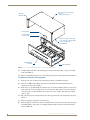
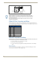
Accessing The Internal Components On An Integrated Controller
1. Carefully detach all connectors from the rear of the unit.
2. Remove the chassis housing screws from both the sides and top of the Controller, as shown in
FIG. 9 by using a grounded screwdriver turning in a counter-clockwise rotation.
The NI-2100 and NI-3100 have six screws on top and three on each side.
The NI-4100 has six screws on top and four on each side.
NI-2100, NI-3100, NI-4100 Hardware Reference Guide
15
Installation and Upgrading
Chassis housing screws (top)
- 6 on top
- sides vary per model
Mounting
Brackets
Compact Flash
Compact Flash
insert location
Chassis housing screws (side)
- 4 on each side of the NI-4100
- 3 on each side of the
NI-3100/2100
NXC Card Slot
faceplate
NXC Card Slots
FIG. 9 Location of the Compact Flash within a sample Integrated Controller
3. Carefully pull-up and remove the housing up and away from the Controller to expose the internal
circuit board (FIG. 9).
4. Refer to the followingInstallation of Compact Flash Upgradesfor detailed replacement information.
Installation of Compact Flash Upgrades
1. Discharge any static electricity from your body by touching a grounded metal object.
2. Locate the 32 MB Compact Flash card on the main board. For more detailed information on
component locations, refer to FIG. 9.
3. Insert the tip of a grounded flathead screwdriver into one of the Card Removal Grooves (located on
either side of the card), and gently pry the card out of the slot. Repeat this process on the opposite
card removal groove. This alternating action causes the card to "wiggle" away from the on-board
connector pins.
4. Slip your finger into the opening between the connector pins and the card, and push the card out to
remove it.
5. Remove the upgrade card from it’s anti-static bag.
6. Insert the upgrade card into the connector opening with the arrow facing towards the pins, then push
it in firmly until the contact pins are completely inside the flash card and securely attached to the
connector (FIG. 10).
16
NI-2100, NI-3100, NI-4100 Hardware Reference Guide
Installation and Upgrading
Under-side groove
located below
Card Removal Grooves
Insert with arrow
facing towards
the connector pins
FIG. 10 Removing the Compact Flash card
7. To complete the upgrade process, close and re-secure the Integrated Controller enclosure using the
procedures outlined in the following section.
Any new internal card upgrade is detected by the Controller only after power is
cycled.
Closing and Securing the Outer Housing
Once the card has been replaced, close and re-secure the outer housing:
1. Align the cover back over the unit and gently slide-down the chassis until the openings are aligned
over their respective openings along both the sides and top of the unit.
2. Insert and secure the chassis housing screws back into their respective locations, as shown in FIG. 9
by using a grounded screwdriver.
3. Re-install all connectors and apply power to the unit.
Installing Into An Equipment Rack
Use the rack-mounting brackets (supplied) for equipment rack installations.
Remove the mounting brackets for flat surface installations.
Before completing the install process, it is recommended that you complete any
firmware upgrade of the NetLinx Control Cards. This upgrade involves physically
cycling power to the unit and can become cumbersome if the unit is already installed
into a rack. Refer to the NI Series NetLinx Integrated Controllers WebConsole &
Programming Guide (available online at www.amx.com) for detailed instructions.
1. Discharge the static electricity from your body by touching a grounded object.
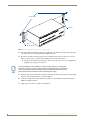
2. Position and install the mounting brackets, as shown in FIG. 11, using the screws supplied with the
unit. The mounting brackets can be rotated to accommodate your mounting needs.
NI-2100, NI-3100, NI-4100 Hardware Reference Guide
17
Installation and Upgrading
Install screws
Bracket
Rack
Mounting Holes
FIG. 11 Mounting Integrated Controller into an equipment rack
3. Thread the cables through the opening in the equipment rack. Allow for enough slack in the cables
to accommodate for movement during the installation process.
4. Reconnect all cables to their appropriate source/terminal locations. Refer to theConnections and
Wiring section on page 19 for more detailed wiring and connection information.
Verify that the terminal end of the power cable is not connected to the a power supply before
plugging in the 2-pin power connector.
To prevent repetition of the installation, test the incoming wiring by connecting the
Controller’s connectors to their terminal locations and applying power. Verify that the
unit is receiving power and functioning properly. Disconnect the terminal end of the
power cable from the connected 12 VDC-compliant power supply.
5. Slide the unit into the rack until the attachment holes, along both sides, align to their corresponding
locations on the mounting brackets, as shown in FIG. 11.
6. Secure the AC-RK to the rack by using the four #10-32 screws (80-0186) and four #10 washers
(80-0342) supplied in the kit.
7. Apply power to the unit to complete the installation.
18
NI-2100, NI-3100, NI-4100 Hardware Reference Guide
Connections and Wiring
Connections and Wiring
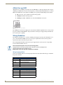
Setting the Configuration DIP Switch (for the Program Port)
Prior to installing the Controller, use the Configuration DIP switch to set the baud rate used by the
Program port for communication. The Configuration DIP switch is located on the front of the Integrated
Controllers.
Baud Rate Settings
Before programming the on-board Master, make sure the baud rate you set matches the communication
parameters set on both your PC’s COM port and those set through your NetLinx Studio v 2.4.
By default, the baud rate is set to 38,400 (bps).
Baud Rate Settings on the Configuration DIP Switch
Baud Rate
Position 5 Position 6 Position 7 Position 8
9600 bps
OFF
ON
OFF
ON
38,400 bps (default) OFF
ON
ON
ON
57,600 bps
ON
OFF
OFF
OFF
115,200 bps
ON
ON
ON
ON
Note the orientation of the Configuration DIP Switch and the ON position label.
DIP switches 2,3, and 4 must remain in the OFF position at all times.
Program Run Disable (PRD) Mode
You can also use the Program port’s Configuration DIP switch to set the on-board Master to Program
Run Disable (PRD) mode according to the settings listed in the table below.
PRD Mode Settings
PRD Mode
Position 1
Normal mode (default) OFF
PRD Mode
ON
The PRD mode prevents the NetLinx program stored in the on-board Master from running when you
power up the Integrated Controller. This mode should only be used when you suspect the resident
NetLinx program is causing inadvertent communication and/or control problems.
If necessary, place the on-board Master in PRD mode and use the NetLinx Studio v 2.4 program to
resolve the communication and/or control problems with the resident NetLinx program. Then download
the new NetLinx program and try again.
NI-2100, NI-3100, NI-4100 Hardware Reference Guide
19
Connections and Wiring
Think of the PRD Mode (On) equating to a PC’s SAFE Mode setting. This mode
allows a user to continue powering a unit, update the firmware, and download a new
program while circumventing any problems with a currently downloaded program.
Power must be cycled to the unit after activating/deactivating this mode on the
Program Port DIP switch #1.
Working With the Configuration DIP Switch
1. Disconnect the power supply from the 2-pin PWR (green) connector on the rear of the NetLinx
Integrated Controller.
2. Set DIP switch positions according to the information listed in theBaud Rate Settings on the
Configuration DIP Switch andPRD Mode Settings tables.
3. Reconnect the 12 VDC-compliant power supply to the 2-pin 3.5 mm mini-Phoenix PWR connector.
Setting the CardFrame DIP Switch (NI-4100 Only)
Refer to the Setting the NetLinx Control Card Addresses (NI-4100 Only) section on page 14 for a
detailed explanation on this process.
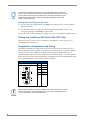
Program Port Connections and Wiring
The Integrated Controllers are equipped with a Program port located on the front of the unit. Use an
RS232 programming cable to establish a connection between this Program port to your PC's COM port.
This connection provides communication with the NetLinx Integrated Controller. Then you can
download NetLinx programs to this on-board Master using the NetLinx Studio v 2.4 software program.
Refer to the NetLinx Studio instruction manual for programming instructions. The following table shows
the rear panel Program Port connector (male), pinouts, and signals.
Program Port, Pinouts, and Signals
Program Port Connector
9
8
5
4
3
2
1
Pin
Signal
2
RX
3
TX
5
GND
7
RTS
8
CTS
7
6
Male
When wiring the 422/485 connections, do NOT use pre-made 9-wire cable or connect
the wire in the cable to any connection that will not be used by the DB9 serial port.
Only use wiring that connects the needed pins.
20
NI-2100, NI-3100, NI-4100 Hardware Reference Guide
Connections and Wiring
Modes and Front Panel LED Blink Patterns
The following table lists the modes and blink patterns for the front panel LEDs associated with each
mode. These patterns are not evident until after the unit is powered.
Modes and LED Blink Patterns
LEDs and Blink Patterns
STATUS
(green)
OUTPUT INPUT
(red)
(yellow)
Mode
Description
OS Start
Starting the operating system (OS).
On
On
On
Boot
On-board Master is booting.
On
Off
On
Contacting DHCP
server
On-board Master is contacting a DHCP
server for IP configuration information.
On
Off
Fast Blink
Unknown DHCP
server
On-board Master could not find the
DHCP server.
Fast Blink
Off
Off
Downloading Boot
firmware
Downloading Boot firmware to the
Master’s on-board flash memory.
Fast Blink
Fast Blink
Fast Blink
No program running
There is no program loaded, or the
program is disabled.
On
Normal
Normal
Normal
On-board Master is functioning normally. 1 blink per second Indicates
activity
Do not cycle power during this process!
Indicates
activity
Port Assignments and Functionality
The Port Assignments are as follows:
NI-2100 Port Assignments
NI-3100/4100 Port Assignments
Port
ICSP Port #
Port
ICSP Port #
Serial Port #1
1
Serial Port #1
1
Serial Port #2
2
Serial Port #2
2
Serial Port #3
3
Serial Port #3
3
Relays Ports (1-4)
4
Serial Port #4
4
IR/Serial Port #1
5
Serial Port #5
5
IR/Serial Port #2
6
Serial Port #6
6
IR/Serial Port #3
7
Serial Port #7
7
IR/Serial Port #4
8
Relays Ports (1-8)
8
I/O Port
9
IR Serial Port #1
9
IR Serial Port #2
10
NI-2100, NI-3100, NI-4100 Hardware Reference Guide
IR Serial Port #3
11
IR Serial Port #4
12
IR Serial Port #5
13
IR Serial Port #6
14
IR Serial Port #7
15
IR Serial Port #8
16
I/O Port
17
21
Connections and Wiring
AXlink Port and LED
All NI units have an AXlink port and adjacent status LED (FIG. 12). This port allows the NI to support
AMX Legacy AXlink devices such as G3 touch panels (ex: CP4/A) and PosiTrack Pilot devices. A green
LED shows AXlink data activity. When the AXlink port is operating normally, blink patterns include:
Off - No power, or the controller is not functioning properly
1 blink per second - Normal operation.
3 blinks per second - AXlink bus error. Check all AXlink bus connections.
FIG. 12 AXlink connector and LED
The AXlink port can be used to supply power to downstream AXlink-compatible devices as long as both
the power required is LESS THAN 2 Amps total and the external power supply feeding the NI unit has
the necessary power capability.
Wiring Guidelines
The Integrated Controllers use a 12 VDC-compliant power supply to provide power through the rear 2pin 3.5 mm mini-Phoenix PWR connector. Use the power requirements referenced in the product’s
Specifications table to determine the power draw.
The incoming PWR and GND cable from the power supply must be connected to the corresponding
locations within the PWR connector.
This unit should only have one source of incoming power.
Using more than one source of power to the Controller can result in damage to the
internal components and a possible burn out.
Apply power to the unit only after installation is complete.
Wiring length guidelines
Refer to the following tables for the wiring length information used with the different types of NetLinx
Integrated Controllers:
Wiring Guidelines - NI-2100 (@ 700 mA)
Wire size
Maximum wiring length
18 AWG
154.83 feet (47.19 meters)
20 AWG
98.30 feet (29.96 meters)
22 AWG
63.40 feet (19.32 meters)
24 AWG
38.68 feet (11.79 meters)
Wiring Guidelines - NI-3100 & NI-4100 (@ 900) mA
22
Wire size
Maximum wiring length
18 AWG
120.41 feet (39.70 meters)
20 AWG
76.45 feet (23.30 meters)
22 AWG
49.36 feet (15.04meters)
24 AWG
30.08 feet (9.17 meters)
NI-2100, NI-3100, NI-4100 Hardware Reference Guide
Connections and Wiring
Preparing Captive Wires
You will need a wire stripper and flat-blade screwdriver to prepare and connect the captive wires.
Never pre-tin wires for compression-type connections.
1. Strip 0.25 inch (6.35 mm) of insulation off all wires.
2. Insert each wire into the appropriate opening on the connector (according to the wiring diagrams
and connector types described in this section).
3. Tighten the screws to secure the wire in the connector. Do not tighten the screws excessively doing
so may strip the threads and damage the connector.
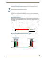
Wiring a Power Connection
To use the 2-pin 3.5 mm mini-Phoenix connector with a 12 VDC-compliant power supply, the incoming
PWR and GND cables from the external source must be connected to their corresponding locations on
connector (FIG. 13).
1. Insert the PWR and GND wires on the terminal end of the 2-pin 3.5 mm mini-Phoenix cable. Match
the wiring locations of the +/- on both the power supply and the terminal connector.
2. Tighten the clamp to secure the two wires. Do not tighten the screws excessively; doing so may strip
the threads and damage the connector.
3. Verify the connection of the 2-pin 3.5 mm mini-Phoenix to the external 12 VDC-compliant power
supply.
PWR +
Power Supply
GND To the Integrated Controller
FIG. 13 2-pin mini-Phoenix connector wiring diagram (direct power)
Using the 4-Pin Mini-Phoenix Connector For Data and Power
Connect the 4-pin 3.5 mm mini-Phoenix (female) captive-wire connector to an external NetLinx device
as shown in FIG. 14.
To the Integrated Controller’s
AXlink/PWR connector
To the external AXlink device
Top view
PWR +
AXM/RX
GND -
AXP/TX
PWR +
AXM/RX
GND -
AXP/TX
Top view
FIG. 14 Mini-Phoenix connector wiring diagram (direct data and power)
NI-2100, NI-3100, NI-4100 Hardware Reference Guide
23
Connections and Wiring
Using the 4-pin Mini-Phoenix Connector For Data With External Power
To use the 4-pin 3.5 mm mini-Phoenix (female) captive-wire connector for data communication and
power transfer, the incoming PWR and GND cable from the 12 VDC-compliant power supply must be
connected to the AXlink cable connector going to the Integrated Controller. FIG. 15 shows the wiring
diagram. Always use a local power supply to power the Integrated Controller unit.
To the Integrated Controller’s
AXlink/PWR connector
PWR (+)
GND (-)
Local +12 VDC
power supply
(coming from
an external
power supply)
To the external AXlink device
Top view
AXM/RX
GND -
AXP/TX
AXM/RX
GND -
AXP/TX
Top view
FIG. 15 4-pin mini-Phoenix connector wiring diagram (using external power source)
When you connect an external power supply, do not connect the wire from the PWR
terminal (coming from the external device) to the PWR terminal on the Phoenix
connector attached to the Controller unit. Make sure to connect only the AXM, AXP,
and GND wires to the Controller’s Phoenix connector when using an external power
supply.
Make sure to connect only the GND wire on the AXlink/PWR connector when using a separate 12 VDC
power supply. Do not connect the PWR wire to the AXlink connector’s PWR (+) opening.
DB9 Device Port: Connections and Wiring
FIG. 16 shows the connector pinouts for the rear RS-232/RS-422/RS-485 (DB9) Device Ports.
These ports support most standard RS-232 communication protocols for data transmission. This figure
gives a visual representation of the wiring specifications for the RS-232/422/485 Device connectors.
Refer to the rear of the unit for more detailed connector pinout information.
DB9 Serial Port pinouts (male connector)
9
8
5
4
3
2
1
7
6
RS-232
RS-422
RS-485
Pin 2: RX signal
Pin 3: TX signal
Pin 5: GND
Pin 7: RTS
Pin 8: CTS
Pin 1: RX Pin 4: TX +
Pin 5: GND
Pin 6: RX +
Pin 9: TX -
Pin 1: A (strap to 9)
Pin 4: B (strap to 6)
Pin 5: GND
Pin 6: B (strap to 4)
Pin 9: A (strap to 1)
Male
FIG. 16 RS-232/422/485 DB9 (male) connector pinouts for the rear Device Ports
24
NI-2100, NI-3100, NI-4100 Hardware Reference Guide
Connections and Wiring
The table below provides information about the connector pins, signal types, and signal functions. This
table’s wiring specifications are applicable to the rear RS-232/422/485 Device Port connectors on the:
NI-2100 (Ports 1-3)
NI-4100/NI-3100 (Ports 1-7)
RS-232/422/485 Device Port Wiring Specifications
Pin Signal Function
RS-232 RS-422 RS-485
1
RX-
Receive data
2
RXD
Receive data
X
3
TXD
Transmit data
X
4
TX+
Transmit data
5
GND
Signal ground
6
RX+
Receive data
7
RTS
Request to send
X
8
CTS
Clear to send
X
9
TX-
Transmit data
X
X
X (strap to pin 9)
X
X (strap to pin 6)
X
X
X (strap to pin 4)
X
X (strap to pin 1)
ICSNet Port: Connections and Wiring
The NI Controller must be equipped with the available ICSNet connectors for this functionality to be
active. The following tables show the signal and pinouts/pairing information:
ICSNet RJ-45 Signals
Pin
Signal-Master
Signal-Device
1
TX +
RX +
2
TX -
RX -
3
N/A
N/A
4
GND
GND
5
N/A
N/A
6
N/A
N/A
7
RX +
TX +
8
RX -
TX -
RJ-45 Pinout Information (EIA/TIA 568 B)
Pin
Wire Color
Polarity
Function
1
Orange/White
+
Transmit
2
Orange
-
Transmit
3
Green/White
-
Mic
4
Blue
-
Ground
5
White/Blue
+
12 VDC
6
Green
+
Mic
7
White/Brown
+
Receive
8
Brown
-
Receive
NI-2100, NI-3100, NI-4100 Hardware Reference Guide
TIA 568B
25
Connections and Wiring
1 2 3 4 5 6 7 8
1 2 3 4 5 6 7 8
(female)
(male)
RJ-45 connector - pin configurations
Unlike the ICSNet ports, the ICSHub connections require a specific polarity. The
IN/OUT configuration, on the hub ports, was implemented to use the same cables as
ICSNet, but these ports need TX and RX crossed. You must connect an OUT to an
IN, or an IN to an OUT port.
This is done simply to keep the polarity straight. The Hub bus is still a bus. All Hub
connections are bi-directional.
ICSHub OUT Port: Connections and Wiring
The NI Controller must be equipped with the available ICSNet connectors for this functionality to be
active. The following table describes the pinout/signal information for the ICSHub OUT port located on
the rear panel of the Integrated Controller.
ICSHub OUT Pinouts and Signals
Pin Signal
Color
1
RX +
orange-white
2
RX -
orange
3
------
------
4
------
------
5
------
------
6
------
------
7
TX +
brown-white
8
TX -
brown
Relay Port: Connections and Wiring
You can connect up to 8 independent external relay devices on both the NI-4100 and NI-3100 units (4 on
the NI-2100) to the Relay connectors on the Integrated Controller.
Connectors labeled A are for common; B are for output.
Each relay is isolated and normally open.
A metal commoning strip is supplied with each Integrated Controller to connect multiple
relays.
Relay Connections
Use A for common and B for output (FIG. 17). Each relay is isolated and normally open. A metal
connector strip is also provided to common multiple relays.
26
NI-2100, NI-3100, NI-4100 Hardware Reference Guide
Connections and Wiring
NI-4100/NI-3100 relay connector
configuration (Port 8)
NI-2100 relay connector
configuration (Port 4)
FIG. 17 RELAY connector (male)
Input/Output (I/O) Port: Connections and Wiring
The I/O port responds to either switch closures, voltage level (high/low) changes, or it can be used for
logic-level outputs.
NI-2100 I/O connector
configuration (Port 9)
NI-4100/NI-3100 I/O connector
configuration (Port 17)
FIG. 18 INPUT/OUTPUT (I/O) connector (male)
A contact closure between the GND and an I/O port is detected as a Push.
When used for voltage inputs, the I/O port detects a low signal (0 - 1.5 VDC) as a Push, and a
high signal (3.5 - 5 VDC) as a Release (this IO port uses 5V logic but can handle up to 12V
without harm).
When used for outputs, the I/O port acts as a switch to GND and is rated for 200mA
@ 12 VDC.
The NI-2100 can use up to 4 I/O ports
The NI-3100 and NI-4100 can use up to 8 I/O ports
The PWR pin provides +12 VDC @ 200 mA and is designed as a power output for the PCS
Power Current Sensors, VSS2 Video Sync Sensors (or equivalent).
The GND connector is a common ground and is shared by all I/O ports. A common ground is
shared with I/O ports 1 - 8 (NI-3100/NI-4100) or with I/O ports 1 - 3 (NI-2100).
I/O Port Wiring Specifications
NI-4100 and NI-3100
I/O Port Wiring Specifications NI-2100
Pin
Signal
Pin
1
GND
Signal GND
1
GND
Signal GND
2
I/O 1
Input/Output
2
I/O 1
Input/Output
3
I/O 2
Input/Output
3
I/O 2
Input/Output
4
I/O 3
Input/Output
4
I/O 3
Input/Output
5
I/O 4
Input/Output
5
I/O 4
Input/Output
6
I/O 5
Input/Output
6
12 VDC
PWR
7
I/O 6
Input/Output
8
I/O 7
Input/Output
Function
9
I/O 8
Input/Output
10
12 VDC
PWR
NI-2100, NI-3100, NI-4100 Hardware Reference Guide
Signal
Function
27
Connections and Wiring
IR/Serial Port: Connections and Wiring
You can connect up to eight IR- or Serial-controllable devices to the IR/Serial connectors on the rear of
the NI-4100 and NI-3100 and up to four on the NI-2100 (FIG. 19).
These connectors accept an IR Emitter (CC-NIRC) that mounts onto the device's IR window, or a miniplug (CC-NSER) that connects to the device's control jack. You can also connect a data 0 - 5 VDC
device.
These units come with two CC-NIRC IR Emitters (FG10-000-11).
NI-2100 IR/Serial connector
configuration (Port 5-8)
NI-4100/NI-3100 IR/Serial connector
configuration (Port 9-16)
FIG. 19 IR/SERIAL (male)
The IR/Serial connector wiring specifications are listed in the following table.
IR/Serial Connector Wiring Specifications (per Port)
Number of
NI-4100/3100 NI-2100
IR connections Port #
Port #
Signal
Function
1
GND (-)
Signal GND
9
5
Signal 1 (+) IR/Serial data
2
10
6
GND (-)
Signal GND
Signal 2 (+) IR/Serial data
3
11
7
GND (-)
4
12
8
GND (-)
1 2 3 4 5 6 7 8
Signal GND
Signal 3 (+) IR/Serial data
Signal GND
Signal 4 (+) IR/Serial data
5
13
N/A
GND (-)
Signal GND
Signal 5 (+) IR/Serial data
6
14
N/A
GND (-)
7
15
N/A
GND (-)
8
16
N/A
GND (-)
Signal GND
1 2 3 4 5 6 7 8
Signal 6 (+) IR/Serial data
Signal GND
Signal 7 (+) IR/Serial data
Signal GND
Signal 8 (+) IR/Serial data
NetLinx Control Card Slot Connector (NI-4100 only)
FIG. 20 shows the 20-pin (male) connector that provides connection to the NetLinx Control Cards.
SLOT 1
20 19 18 17 16 15 14 13 12 11 10 9 8 7 6 5 4 3 2 1
FIG. 20 NetLinx Control Card 20-pin connector
28
NI-2100, NI-3100, NI-4100 Hardware Reference Guide
Connections and Wiring
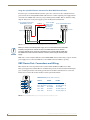
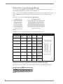
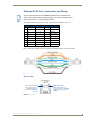
Ethernet/RJ-45 Port: Connections and Wiring
NI-x100 Controllers feature an Auto MDI/MDI-X Ethernet port. This provides the
option of using either a standard (straight through), or a crossover Ethernet cable to
communicate with a PC - both cable types will work.
The following table lists the pinouts, signals, and pairing for the Ethernet connector.
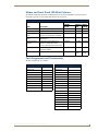
Ethernet RJ-45 Pinouts and Signals
Pin Signals
Connections Pairing
1
TX +
1 --------- 1
2
TX -
2 --------- 2
3
RX +
3 --------- 3
4
no connection 4 --------- 4
Blue
5
no connection 5 --------- 5
Blue-White
6
RX -
7
no connection 7 --------- 7
Brown-White
8
no connection 8 --------- 8
Brown
6 --------- 6
Color
1 --------- 2 Orange-White
Orange
3 --------- 6 Green-White
Green
FIG. 21 diagrams the RJ-45 pinouts and signals for the Ethernet RJ-45 connector and cable.
FIG. 21 RJ-45 wiring diagram
Ethernet LEDs
L/A - Link/Activity LED
lights (green) when the
Ethernet cables are
connected and terminated
correctly.
SPD - Speed LED
lights (yellow) when the
connection speed is 100 Mbps
and turns Off when speed is
10 Mbps.
FIG. 22 Ethernet LEDs
NI-2100, NI-3100, NI-4100 Hardware Reference Guide
29
Connections and Wiring
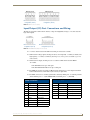
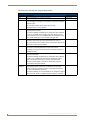
Ethernet Ports Used By the Integrated Controller
Ethernet Port Descriptions
Port type
Description
Standard Port #
FTP
The on-board Master has a built-in FTP server.
21/20 (TCP)
SSH
The SSH port functions using the same interface as Telnet but over a
22 (TCP)
secure shell where it uses SSL as a mechanism to configure and diagnose
a NetLinx system.
This port value is used for secure Telnet communication.
Note: SSH version 2 is only supported.
Telnet
The NetLinx Telnet server provides a mechanism to configure and
diagnose a NetLinx system.
23 (TCP)
For maximum flexibility, the Master can be configured to utilize a different
port than 23, or disable Telnet completely from either Telnet or the Program Port located on the rear of the Master itself. Once disabled, the only
way to enable Telnet again is from the Master’s Program port.
HTTP
The Master has a built-in web server that complies with the HTTP 1.0
specification and supports all of the required features of HTTP v1.1.
80 (TCP)
This port is used for unsecure HTTP Internet communication between the
web browser’s UI and the target Master.
HTTPS/SSL This port is used by a web browser to securely communicate between the
web server UI and the target Master. This port is also used to
simultaneously encrypt this data using the SSL certificate information on
the Master as a key.
443 (TCP)
ICSP
1319 (UDP/TCP)
Peer-to-peer protocol used for both Master-to-Master and Master-todevice communications.
For maximum flexibility, the Master can be configured to utilize a different
port than 1319, or disable ICSP over Ethernet completely from either
Telnet or the Program Port located on the rear of the Master itself.
This type of communication is used by the various AMX product for
communication amongst themselves.
integration!
Solutions
This feature on the Master uses, by default, port 10500 for the XML based
communication protocol. This port is connected to by the client web
browser’s JVM when integration! Solutions control pages are retrieved
from the on-board Master’s web server.
10500 (TCP)
For maximum flexibility, the on-board Master can be configured to utilize a
different port than 10500 or to disable integration! Solutions completely.
30
NI-2100, NI-3100, NI-4100 Hardware Reference Guide
Connections and Wiring
NI-2100, NI-3100, NI-4100 Hardware Reference Guide
31
AMX. All rights reserved. AMX and the AMX logo are registered trademarks of AMX. AMX reserves the right to alter specifications without notice at any time.
©2009
1/2009
It’s Your World - Take Control™
3000 RESEARCH DRIVE, RICHARDSON, TX 75082 USA • 800.222.0193 • 469.624.8000 • 469-624-7153 fax • 800.932.6993 technical support • www.amx.com