1
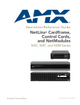
Operation/Reference Guide
NetLinx® Cardframe,
Control Cards, and
NetModules
NXC, NXF, and NXM Series
Controllers
L a s t R e v i s e d : 1 /8 / 2 0 0 9
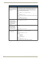
AMX Limited Warranty and Disclaimer
AMX Corporation warrants its products to be free of defects in material and workmanship under normal use for three (3) years from
the date of purchase from AMX Corporation, with the following exceptions:
•
Electroluminescent and LCD Control Panels are warranted for three (3) years, except for the display and touch overlay components that are warranted for a period of one (1) year.
•
Disk drive mechanisms, pan/tilt heads, power supplies, and MX Series products are warranted for a period of one (1) year.
•
AMX Lighting products are guaranteed to switch on and off any load that is properly connected to our lighting products, as long
as the AMX Lighting products are under warranty. AMX Corporation does guarantee the
control of dimmable loads that are properly connected to our lighting products. The dimming performance or quality cannot be
guaranteed due to the random combinations of dimmers, lamps and ballasts or transformers.
•
Unless otherwise specified, OEM and custom products are warranted for a period of one (1) year.
•
AMX Software is warranted for a period of ninety (90) days.
•
Batteries and incandescent lamps are not covered under the warranty.
This warranty extends only to products purchased directly from AMX Corporation or an Authorized AMX Dealer.
All products returned to AMX require a Return Material Authorization (RMA) number. The RMA number is obtained from the AMX
RMA Department. The RMA number must be clearly marked on the outside of each box. The RMA is valid for a 30-day period. After
the 30-day period the RMA will be cancelled. Any shipments received not consistent with the RMA, or after the RMA is cancelled, will
be refused. AMX is not responsible for products returned without a valid RMA number.
AMX Corporation is not liable for any damages caused by its products or for the failure of its products to perform. This includes any
lost profits, lost savings, incidental damages, or consequential damages. AMX Corporation is not liable for any claim made by a third
party or by an AMX Dealer for a third party.
This limitation of liability applies whether damages are sought, or a claim is made, under this warranty or as a tort claim (including
negligence and strict product liability), a contract claim, or any other claim. This limitation of
liability cannot be waived or amended by any person. This limitation of liability will be effective even if AMX Corporation or an authorized representative of AMX Corporation has been advised of the possibility of any such damages. This limitation of liability, however,
will not apply to claims for personal injury.
Some states do not allow a limitation of how long an implied warranty last. Some states do not allow the limitation or exclusion of incidental or consequential damages for consumer products. In such states, the limitation or exclusion of the Limited Warranty may not
apply. This Limited Warranty gives the owner specific legal rights. The owner may also have other rights that vary from state to state.
The owner is advised to consult applicable state laws for full
determination of rights.
EXCEPT AS EXPRESSLY SET FORTH IN THIS WARRANTY, AMX CORPORATION MAKES NO
OTHER WARRANTIES, EXPRESSED OR IMPLIED, INCLUDING ANY IMPLIED WARRANTIES OF
MERCHANTABILITY OR FITNESS FOR A PARTICULAR PURPOSE. AMX CORPORATION
EXPRESSLY DISCLAIMS ALL WARRANTIES NOT STATED IN THIS LIMITED WARRANTY. ANY
IMPLIED WARRANTIES THAT MAY BE IMPOSED BY LAW ARE LIMITED TO THE TERMS OF THIS
LIMITED WARRANTY.
Software License and Warranty Agreement
LICENSE GRANT.
AMX grants to Licensee the non-exclusive right to use the AMX Software in the manner described in this License. The AMX Software is
licensed, not sold. This license does not grant Licensee the right to create derivative works of the AMX Software. The AMX Software consists
of generally available programming and development software, product documentation, sample applications, tools and utilities, and
miscellaneous technical information. Please refer to the README.TXT file on the compact disc or download for further information regarding
the components of the AMX Software. The AMX Software is subject to restrictions on distribution described in this License Agreement.
LICENSEE MAY NOT SUBLICENSE, RENT, OR LEASE THE AMX SOFTWARE. Licensee may not reverse engineer, decompile, or
disassemble the AMX Software.
INTELLECTUAL PROPERTY.
The AMX Software is owned by AMX and is protected by United States copyright laws, patent laws, international treaty provisions, and/or state
of Texas trade secret laws. Licensee may make copies of the AMX Software solely for backup or archival purposes. Licensee may not copy
the written materials accompanying the AMX Software.
TERMINATION.
AMX RESERVES THE RIGHT, IN ITS SOLE DISCRETION, TO TERMINATE THIS LICENSE FOR ANY REASON AND UPON WRITTEN
NOTICE TO LICENSEE. In the event that AMX terminates this License, the Licensee shall return or destroy all originals and copies of the
AMX Software to AMX and certify in writing that all originals and copies have been returned or destroyed.
PRE-RELEASE CODE.
Portions of the AMX Software may, from time to time, as identified in the AMX Software, include PRE-RELEASE CODE and such
code may not be at the level of performance, compatibility and functionality of the final code. The PRE-RELEASE CODE may not
operate correctly and may be substantially modified prior to final release or certain features may not be generally released. AMX is
not obligated to make or support any PRE-RELEASE CODE. ALL PRE-RELEASE CODE IS PROVIDED "AS IS" WITH NO
WARRANTIES.
LIMITED WARRANTY.
AMX warrants that the AMX Software will perform substantially in accordance with the accompanying written materials for a period of ninety
(90) days from the date of receipt. AMX DISCLAIMS ALL OTHER WARRANTIES, EITHER EXPRESS OR IMPLIED, INCLUDING, BUT NOT
LIMITED TO IMPLIED WARRANTIES OF MERCHANTABILITY AND FITNESS FOR A PARTICULAR PURPOSE, WITH REGARD TO THE
AMX SOFTWARE. THIS LIMITED WARRANTY GIVES LICENSEE SPECIFIC LEGAL RIGHTS. Any supplements or updates to the AMX
SOFTWARE, including without limitation, any (if any) service packs or hot fixes provided to Licensee after the expiration of the ninety (90) day
Limited Warranty period are not covered by any warranty or condition, express, implied or statutory.
LICENSEE REMEDIES.
AMX's entire liability and Licensee's exclusive remedy shall be repair or replacement of the AMX Software that does not meet AMX's Limited
Warranty and which is returned to AMX. This Limited Warranty is void if failure of the AMX Software has resulted from accident, abuse, or
misapplication. Any replacement AMX Software will be warranted for the remainder of the original warranty period or thirty (30) days,
whichever is longer. Outside the United States, these remedies may not available.
NO LIABILITY FOR CONSEQUENTIAL DAMAGES. IN NO EVENT SHALL AMX BE LIABLE FOR ANY DAMAGES WHATSOEVER
(INCLUDING, WITHOUT LIMITATION, DAMAGES FOR LOSS OF BUSINESS PROFITS, BUSINESS INTERRUPTION, LOSS OF BUSINESS
INFORMATION, OR ANY OTHER PECUNIARY LOSS) ARISING OUT OF THE USE OF OR INABILITY TO USE THIS AMX SOFTWARE,
EVEN IF AMX HAS BEEN ADVISED OF THE POSSIBILITY OF SUCH DAMAGES. BECAUSE SOME STATES/COUNTRIES DO NOT
ALLOW THE EXCLUSION OR LIMITATION OF LIABILITY FOR CONSEQUENTIAL OR INCIDENTAL DAMAGES, THE ABOVE LIMITATION
MAY NOT APPLY TO LICENSEE.
U.S. GOVERNMENT RESTRICTED RIGHTS.
The AMX Software is provided with RESTRICTED RIGHTS. Use, duplication, or disclosure by the Government is subject to
restrictions as set forth in subparagraph ©(1)(ii) of The Rights in Technical Data and Computer Software clause at DFARS 252.2277013 or subparagraphs ©(1) and (2) of the Commercial Computer Software Restricted Rights at 48 CFR 52.227-19, as applicable.
SOFTWARE AND OTHER MATERIALS FROM AMX.COM MAY BE SUBJECT TO EXPORT CONTROL.
The United States Export Control laws prohibit the export of certain technical data and software to certain territories. No software from this Site
may be downloaded or exported (i) into (or to a national or resident of) Cuba, Iraq, Libya, North Korea, Iran, Syria, or any other country to
which the United States has embargoed goods; or (ii) anyone on the United States Treasury Department's list of Specially Designated Nationals or the U.S. Commerce Department's Table of Deny Orders. AMX does not authorize the downloading or exporting of any software or technical data from this site to any jurisdiction prohibited by the United States Export Laws.
This Agreement replaces and supersedes all previous AMX Software License Agreements and is governed by the laws of the State of Texas,
and all disputes will be resolved in the courts in Collin County, Texas, USA. For any questions concerning this Agreement, or to contact AMX
for any reason, please write: AMX Corporation, 3000 Research Drive, Richardson, TX 75082.
Table of Contents
Table of Contents
NXF CardFrame and NetModules ......................................................................1
NXF CardFrame ........................................................................................................ 1
NXF Cardframe Specifications ................................................................................. 2
Mounting Master/Hub Cards in an NXF CardFrame........................................................ 2
Setting the CardFrame's starting address....................................................................... 3
Device:Port:System (D:P:S).............................................................................................. 3
NXS-NMS NetModules ............................................................................................. 4
NXS-NMS NetModules specifications ............................................................................. 4
Mounting modules into an equipment rack..................................................................... 4
Installing Control Cards into an NXF CardFrame ............................................................ 5
Preparing/connecting captive wires ................................................................................ 5
Using the ID button......................................................................................................... 5
NXC-COM2 Dual COM Port Control Card ..........................................................7
Specifications............................................................................................................ 7
Pinouts and Wiring Configuration ............................................................................ 8
NXC-COM2 Channel Assignment.............................................................................. 8
NXC-COM2 Programming Information ..................................................................... 9
NXC-COM2 Send_Commands ......................................................................................... 9
NXC-COM2 Send_String Escape Sequences ................................................................. 12
NXC-I/O10 Input/Output Control Card ............................................................15
Specifications.......................................................................................................... 15
Pinouts, Signals, and I/O Mode Functions .............................................................. 16
NXC-I/O10 Channel Assignments ........................................................................... 16
Setting the Switch/Voltage Mode Jumpers ............................................................ 17
Setting the Voltage Clamp Jumper (+12V or Open)............................................... 17
NXC-IRS4 4-Port IR/S Control Card ..................................................................19
Specifications.......................................................................................................... 19
Pinouts, Signals, and Functions .............................................................................. 20
NXC-IRS4 Channel Assignments ............................................................................. 20
Programming Information....................................................................................... 20
NXC-REL10 Relay Control Card ........................................................................27
Specifications.......................................................................................................... 27
Pinouts and Functions............................................................................................. 27
NXC-REL10 Channel Assignments .......................................................................... 27
NXC-REL10 Connections/Wiring ............................................................................. 28
Enter the Document Name Here
i
Table of Contents
NXC-VAI4 Analog Voltage Control Card ..........................................................29
Specifications .......................................................................................................... 29
Pinouts and Functions ............................................................................................. 30
Channel Assignments.............................................................................................. 31
NXC-VAI4 Output Level Assignments ..................................................................... 33
NXC-VAI4 Input Level Assignments ........................................................................ 34
Programming Information....................................................................................... 34
NXC-VOL4 Volume Control Card ......................................................................41
Specifications .......................................................................................................... 41
Pinouts, Signals, and Functions............................................................................... 42
NXC-VOL4 Connections/Wiring .............................................................................. 43
NXC-VOL4 Channel Assignments............................................................................ 43
NXC-VOL4 Levels.................................................................................................... 44
CREATE_LEVEL.............................................................................................................. 44
SEND_LEVEL ................................................................................................................. 44
Programming Information....................................................................................... 45
ii
Enter the Document Name Here
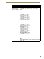
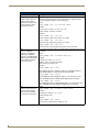
NXF CardFrame and NetModules
NXF CardFrame and NetModules
NetLinx Control Cards can be installed in the NetLinx® (NXF) CardFrame, the NI-4000, or in modules for
stand-alone operation. The NXF CardFrame accommodates a NetLinx Master (or Hub) card, up to twelve
NetLinx Control cards, and provides a back plane to distribute power and data to/from the cards. The NXF
CardFrame provides terminals on the rear panel for connection to the control cards and a system power supply.
A DIP switch on the rear panel sets the CardFrame's base device number.
The NetLinx Control Cards covered in this document are:
• NXC-COM2
Dual COM Port Control Card
• NXC-I/O10
Input/Output Control Card
• NXC-IRS4
4-Port IR/S Control Card
• NXC-REL10
Relay Control Card
• NXC-VAI4
Analog Voltage Control Card
• NXC-VOL4
Volume Control Card
NXF CardFrame
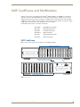
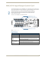
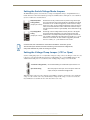
FIG. 1 shows the front and rear panel components of the NXF CardFrame.
Control Card slots 1-12
1
2
3
4
5
6
7
8
9
10
11
12
1
2
3
4
5
6
7
8
9
10
11
12
Master/Hub Card slot
Cardframe number DIP Switch
2-pin 12V power connector
front
12
11
1
10
9
1
8
7
1
6
5
1
4
3
1
2
12VDC
2
2
2
2
2
2
2
2
2
2
2
3
3
3
3
3
3
3
3
3
3
3
3
4
4
4
4
4
4
4
4
4
4
4
4
5
5
5
5
5
5
5
5
5
5
5
5
6
6
7
6
7
8
6
7
8
6
7
8
6
7
8
6
7
8
6
7
8
6
7
8
6
7
8
6
7
8
8
9
9
9
9
9
9
9
9
9
9
9
10
10
10
10
10
10
10
10
10
10
10
11
11
11
11
11
11
11
11
11
11
11
11
12
12
12
12
12
12
12
12
12
12
12
12
13
13
13
13
13
13
13
13
13
13
13
13
14
14
14
14
14
14
14
14
14
14
14
14
15
15
15
15
15
15
15
15
15
15
15
15
16
16
16
16
16
16
16
16
16
16
16
16
17
17
18
18
17
18
19
19
17
18
19
12
11
17
18
19
17
18
19
20
20
9
rear
17
18
19
17
18
19
20
10
7
17
18
19
17
18
19
20
8
5
Master/Hub Card slot
17
18
19
18
19
20
6
CARDFRAME
CARDFRAME
PWR
7
8
9
10
17
CARDFRAME NUMBER
ON
6
7
8
NXF
1
1
2
19
20
4
3
2
1
Control Card slots 1-12
FIG. 1 NXF CardFrame
NetLinx Cardframe, Control Cards, and NetModules
1
NXF CardFrame and NetModules
NXF Cardframe Specifications
NXF Cardframe Specifications
Power Requirement
12 VDC; varies with installed Control Cards.
Dimensions (HWD)
3.5" x 17.0" x 9.6" (8.89 cm x 43.18 cm x 24.38 cm)
Weight
9.1 lbs (4.1 kg)
Front Panel Components:
Master/Hub Card slot
Houses the Master or Hub Card. Refer to the NetLinx Master Cards and
Modules or NetLinx Hub Cards and Modules instruction manuals for
detailed information.
Control Card slots
12 card slots for the NetLinx Control Cards that control devices connected
to the CardFrame.
Rack-mounting brackets
Provides for installing the CardFrame into an equipment rack.
Rear Panel Components:
Card slots
Twelve 20-pin black (male) connectors and mating 3.5 mm captive-screw
terminals supplied with Control Cards.
Control Card connectors (1-12)
20-pin black (male) connectors that connect the Control Cards and external equipment to the CardFrame.
+12 VDC PWR
2-pin green (male) connector for connecting a 12 VDC power supply. The
CardFrame can be powered via the Master Card (default) or by an external power supply connected to the CardFrame's PWR connector. If a
power supply is connected to the PWR connector, the CardFrame power
automatically switches to the connected power supply. In that case, the
Control Cards and CardFrame are independently powered.
A simple rule to follow is that if the CardFrame contains eight or more
Control Cards, use two 12 VDC power supplies.
CardFrame Number DIP switch
Sets the starting address for the Control Cards in the CardFrame. The
8-position DIP switch address range is 1-3072.
Front faceplate
Plastic gray faceplate with translucent viewing window.
Enclosure
Metal with black matte finish.
Mounting Master/Hub Cards in an NXF CardFrame
NetLinx Master and Hub Cards can be installed in the NXF CardFrame. The card mounts in a horizontal
position, through the master card slot on the rear panel of the NXF enclosure. To install a Master or Hub Card
in an NXF:
1.
2.
3.
4.
5.
6.
7.
Discharge the static electricity from your body by touching a grounded metal object.
Unplug all the connectors from the NXF.
Remove the two screws holding the front plate on the Master Card, and remove the front plate.
Align the edges of the card with the guide slots inside the Master Card slot on the NXF.
Slide the card about halfway into the slot.
Inside the Master Card slot on the NXF, locate the 6-pin control cable connector.
Plug the connector from the NXF into the 6-pin terminal on the Master Card. This connector is keyed to
ensure correct orientation.
8. Once the control cable is connected, gently slide the card all the way in until you feel the rear edge of the
card lightly snap into place.
9. Re-apply power and other connections as necessary.
2
NetLinx Cardframe, Control Cards, and NetModules
NXF CardFrame and NetModules
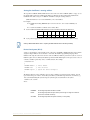
Setting the CardFrame's starting address
The 8-position CardFrame Number DIP switch, located on the rear of the CardFrame (FIG. 1 on page 1), sets
the starting address (the device number in the D:P:S specification) for the Control Cards installed in the
CardFrame. The address range is 12-3060. The formula for setting the starting address is:
(DIP switch address x 12) + Card slot Number (1-12) = Card address
For example:
For DIP switch setting, 00010101: (0 + 0 + 0 + 0 + 96 + 0 + 384 + 1536) + SLOT #(ex:1)
= 2017.
A card in slot number 7 would be device address 2023.
1. Set the CardFrame Number DIP switch based on the information listed in the table below.
Positio
n
1
2
3
4
5
6
7
8
Value
12
24
48
96
192
384
768
1536
2. Cycle power for approximately 5 seconds, so the system can read the new device number settings.
Factory default DIP switch value = 0 (zero) (All DIP switches are in the OFF position).
Device:Port:System (D:P:S)
A device is any hardware component that can be connected to an AXlink or ICSNet bus. Each device must be
assigned a unique number to locate that device on the bus. The NetLinx programming language allows
numbers in the range 0-32,767. Device 0 refers to the local Master; numbers greater than 32,767 are reserved.
NetLinx requires a Device:Port:System (D:P:S) specification. This D:P:S triplet can be expressed as a series of
constants, variables separated by colons, or a DEV structure. For example:
STRUCTURE DEV
{
INTEGER Number
// Device number
INTEGER Port
// Port on device
INTEGER System
// System the device belongs to
}
The D:P:S notation is used to explicitly represent a device number, port and system. For example, 128:1:0
represents the first port on device 128 on this system. If the system and Port specifications are omitted, (e.g.
128), system 0 (indicating this system) and port 1 (the first port) is assumed. Here's the syntax:
NUMBER:PORT:SYSTEM
where:
NUMBER:
16-bit integer represents the device number
PORT:
16-bit integer represents the port number (in the range 1 through the number of
ports on the Controller or device)
SYSTEM:
16-bit integer represents the system number (0 = this system)
NetLinx Cardframe, Control Cards, and NetModules
3
NXF CardFrame and NetModules
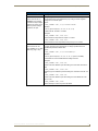
NXS-NMS NetModules
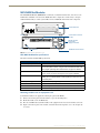
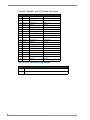
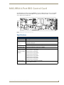
The NXS-NMS NetModules (FG2009-10) accommodate one NetLinx Control Card, and connect to the
NetLinx bus via ICSNet connections. The NetModules offer a simple and economical way to integrate
additional functionality to control systems. FIG. 2 shows a NetModule shell and its main components.
Control Card slot
NetModule
front
NXM-NMS
Control Card connector
(20-pin)
20 19 18 17 16 15 14 13 12 11 10 9
8
7
6
5
4
3
2
1
NetModule
12VDC
ID
rear
ICSNet
Parallel 12 VDC
2-pin power
supply connectors
PWR
ID Button
ICSNet RJ-45 connectors
FIG. 2 NXS-NMS NetLinx NetModule shell
NXS-NMS NetModules specifications
The table below lists the NXS-NMS specifications.
NXS-NMS NetModules Specifications
Dimensions (HWD)
1.50" x 5.55" x 9.25" (3.81 cm x 14.10 cm x 23.50 cm)
ID button
Generates an event from the NetModule to allow you to assign new
Device and System numbers, using ID mode in the NetLinx Studio software program (seeUsing the ID button section on page 5 for details).
Control connector
20-pin black (male) connector that connects the NetModule to external
devices. These connectors are keyed to insure proper installation.
ICSNet RJ-45 connectors
Receives power and data from a NetLinx Master/Hub ICSNet Port. An
ICSNet port on a NetLinx Master or Hub supplies up to 500 mA at 12 V
for module power.
12 VDC power supply connectors Two parallel male 2-pin (green) parallel connectors for 12 VDC power.
Enclosure
Metal with black matte finish
Included Accessories
NetLinx faceplate
Optional accessories
AC-RK Accessory Rack Kit (holds up to three NetModules)
Mounting modules into an equipment rack
To install the modules in an equipment rack using the optional AC-RK kit:
1.
2.
3.
4.
4
Remove the front faceplate from the module to expose the mounting holes.
Mount the module on the AC-RK bracket.
Place the AC-RK bracket (with the module) in the equipment rack and secure the bracket to the rack.
Replace the front faceplate on the module, and attach the translucent plastic cover to the faceplate (if
necessary).
NetLinx Cardframe, Control Cards, and NetModules
NXF CardFrame and NetModules
Installing Control Cards into an NXF CardFrame
1. Remove the magnetic front faceplate/viewing window from the CardFrame.
2. Align the edge of the Control Card with a slot in the CardFrame. Slide the card into the CardFrame and
press until you feel the Card seat in the backplane connector.
3. Put the magnetic faceplate back on the CardFrame. Secure with mounting screws (if necessary).
Preparing/connecting captive wires
1. Strip 0.25 inch of wire insulation off all wires.
2. Insert each wire into the appropriate opening on the connector according to the wiring diagrams and
connector types described in this section.
3. Tighten the screws to secure the wires in the connector. Do not tighten the screws excessively; doing so
may strip the threads and damage the connector.
Using the ID button
The ID Button on the rear panel of the NetModules (see FIG. 2) is used in conjunction with the NetLinx Studio
software program to allow you to assign new Device and System numbers for the Module.
1. Using NetLinx Studio, place the system in Identity (ID) Mode. ID Mode means the entire system is put
on hold while it waits for an event from any NetLinx device in the named system (for example, pushing
the ID button on a Module). The device generating the first event is the identified device.
2. Press the ID Mode button to generate an event from the Module and allow you to assign new Device and
System numbers in NetLinx Studio.
NetLinx Cardframe, Control Cards, and NetModules
5
NXF CardFrame and NetModules
6
NetLinx Cardframe, Control Cards, and NetModules
NXC-COM2 Dual COM Port Control Card
NXC-COM2 Dual COM Port Control Card
The NXC-COM2 Dual COM Port Control Card (FG2022) provides two RS-232, RS-422, or
RS-485 control ports and LED feedback for remote sources connected to the NetLinx CardFrame, NI-4000 or
NetModule. FIG. 3 shows the COM2 card.
ICSNET Status LED
LED 1
LED 4
FIG. 3 NXC-COM2 Dual COM Port Control card
Specifications
NXC-COM2 Specifications
Power Requirements:
140 mA @ 12 VDC
Operation:
Data 1-2: Two RS-232/422/485 control ports,
supports XON/XOFF, CTS/RTS, 300-230,400 baud
Status LEDs (2 per channel):
• Red LED shows TX (transmit) data activity
• Yellow LED shows RX (receive) data activity
- LED 1: CH1 TX (red)
- LED 2: CH1 RX (yellow)
- LED 3: CH2 TX (red)
- LED 4: CH2 RX (yellow)
• Green ICSP status LED (located on the board):
- On = card is not in communication with the Master.
- Blinks (1-second intervals) during normal operation.
Connections/wiring:
Two 10-pin 3.5 mm captive-screw terminals
DEVICE_ID:
$0107
NetLinx Cardframe, Control Cards, and NetModules
7
NXC-COM2 Dual COM Port Control Card
Pinouts and Wiring Configuration
NXC-COM2 Pinouts
Pin
Signal
Function
1
GND
2
3
NXC-COM2 Wiring Configuration
RS-232
RS422
RS-485
Signal ground
X
X
RXD1
Receive data
X
TXD1
Transmit data
X
4
CTS1
Clear to send
X
5
RTS1
Request to send
X
6
TX1+
Transmit data
X
X
(strap to pin 8)
7
TX1-
Transmit data
X
X
(strap to pin 9)
8
RX1+
Receive data
X
X
(strap to pin 6)
9
RX1-
Receive data
X
X
(strap to pin 7)
10
+12 VDC
Power
11
GND
Signal ground
12
RXD2
Receive data
X
13
TXD2
Transmit data
X
14
CTS2
Clear to send
X
15
RTS2
Request to send
X
16
TX2+
Transmit data
X
X
(strap to pin 18)
17
TX2-
Transmit data
X
X
(strap to pin 19)
18
RX2+
Receive data
X
X
(strap to pin 16)
19
RX2-
Receive data
X
X
(strap to pin 17)
20
+12 VDC
Power
Optional Optional
X
X
Optional Optional
NXC-COM2 Channel Assignment
NXC-COM2 Channel Assignment
Channe Description
l
255
8
CTS push channel - reflects the state of the CTS input if a 'CTSPSH' command
was sent to the device.
NetLinx Cardframe, Control Cards, and NetModules
NXC-COM2 Dual COM Port Control Card
NXC-COM2 Programming Information
NXC-COM2 Send_Commands
NXC-COM2 Send_Commands
Command
Description
B9MOFF
This command works in conjunction with the B9MON command.
Disable 9-bit in 232/422/
455 mode.
Syntax:
SEND_COMMAND <DEV>,"'B9MOFF'"
Example:
SEND_COMMAND SOMEDEVICE_1,"'B9MOFF'"
Sets the port settings on SOMEDEVICE to match the port's configuration settings.
B9MON
This command works in conjunction with the B9MOFF command.
Enable 9-bit in
232/422/455 mode.
Syntax:
SEND_COMMAND <DEV>,"'B9MON'"
Example:
SEND_COMMAND SOMEDEVICE_1,"'B9MON'"
Resets the SOMEDEVICE port's communication parameters to nine data bits and
one stop bit.
CHARD
Set the delay time
between all transmitted
characters to the value
specified (in 100
microsecond increments).
Syntax:
SEND_COMMAND <DEV>,"'CHARD-<time>'"
Variable:
time: 0 - 255. Measured in 100 microsecond increments.
Example:
SEND_COMMAND RS232_1,"'CHARD10'"
Sets a 1-millisecond delay between all transmitted characters.
CHARDM
Set the delay time
between all transmitted
characters to the value
specified (in 1 millisecond
increments).
Syntax:
SEND_COMMAND <DEV>,"'CHARDM-<time>'"
Variable:
time: 0 - 255. Measured in 1 millisecond increments.
Example:
SEND_COMMAND RS232_1,"'CHARDM10'"
Sets a 10-millisecond delay between all transmitted characters.
CTSPSH
If Clear To Send (CTS) is high, the channel is On.
Enable Pushes, Releases, Syntax:
and status information to
SEND_COMMAND <DEV>,"'CTSPSH'"
be reported via channel
Example:
255 using the CTS
hardware handshake
SEND_COMMAND RS232_1,"'CTSPSH'"
input.
Sets the RS232_1 port to detect changes on the CTS input.
CTSPSH OFF
Turns CTSPSH Off. If Clear To Send (CTS) is high, the channel is on.
Disable Pushes,
Releases, and Status
information to be reported
via channel 255.
Syntax:
SEND_COMMAND <DEV>,"'CTSPSH OFF'"
Example:
SEND_COMMAND RS232_1,"'CTSPSH OFF'"
Turns off CTSPSH for the specified device. Disables the RS232_1 port to detect
changes on the CTS input.
NetLinx Cardframe, Control Cards, and NetModules
9
NXC-COM2 Dual COM Port Control Card
NXC-COM2 Send_Commands (Cont.)
Command
Description
GET BAUD
Device sends the response out the Master program port.
Get the RS-232/422/485
port’s current
communication
parameters.
Syntax:
SEND_COMMAND <DEV>,"'GET BAUD'"
Example:
SEND_COMMAND RS232_1,"'GET BAUD'"
Device responds with:
<port #>,<baud>,<parity>,<data>,<stop> 485 <ENABLED | DISABLED>
HSOFF
Disable hardware
handshaking (default).
Syntax:
SEND_COMMAND <DEV>,"'HSOFF'"
Example:
SEND_COMMAND RS232_1,"'HSOFF'"
Disables hardware handshaking on the RS232_1 device.
HSON
Syntax:
Enable RTS (ready-tosend) and CTS (clear-tosend) hardware
handshaking.
Example:
SEND_COMMAND <DEV>,"'HSON'"
SEND_COMMAND RS232_1,"'HSON'"
Enables hardware handshaking on the RS232_1 device.
RXCLR
Syntax:
Clear all characters in the
SEND_COMMAND <DEV>,"'RXCLR'"
receive buffer waiting to be
Example:
sent to the Master.
SEND_COMMAND RS232_1,"'RXCLR'"
Clears all characters in the receive buffer waiting to be sent to the Master.
RXOFF
Syntax:
Disable the transmission
of incoming received
characters to the Master
(default).
Example:
SEND_COMMAND <DEV>,"'RXOFF'"
SEND_COMMAND RS232_1,"'RXOFF'"
Disable the transmission of incoming received characters to the Master (default).
RXON
Start transmitting received
characters to the Master
(default).
Enables sending incoming received characters to the Master. This command is
automatically sent by the Master when a 'CREATE_BUFFER' program instruction
is executed.
Syntax:
SEND_COMMAND <DEV>,"'RXON'"
Example:
SEND_COMMAND RS232_1,"'RXON'"
Stops the RS232_1 device from transmitting received characters to the Master.
10
NetLinx Cardframe, Control Cards, and NetModules
NXC-COM2 Dual COM Port Control Card
NXC-COM2 Send_Commands (Cont.)
Command
Description
SET BAUD
Syntax:
Set the RS-232/422/485
port's communication
parameters.
SEND_COMMAND <DEV>,"'SET BAUD <baud>,<parity>,<data>,<stop>
[485 <Enable | Disable>]'"
Variables:
Baud: baud rates are: 230400, 115200, 76800, 57600, 38400, 19200, 9600,
4800, 2400, 1200, 600, 300, 150.
Parity: N (none), O (odd), E (even), M (mark), S (space)
Data: 7 or 8 data bits
Stop: 1 or 2 stop bits
485 Disable: Disables RS-485 mode and enables RS-232/422
485 Enable: Enables RS-485 mode and disables RS-234/422
Note: The only valid 9 bit combination is (baud),N,9,1.
Example:
SEND_COMMAND SOMEDEVICE_1,"'SET BAUD 115200,N,8,1, 485
ENABLE'"
Sets the SOMEDEVICE port's communication parameters to 115,200 baud, no
parity, 8 data bits, 1 stop bit, and enables RS-485 mode.
TSET BAUD
Temporarily set the
RS-232/422/485 port's
communication
parameters for a device.
TSET BAUD works the same as SET BAUD, except that the changes are not
permanent, and the previous values will be restored if the power is cycled on the
device.
Syntax:
SEND_COMMAND <DEV>,"'TSET BAUD
<baud>,<parity>,<data>,<stop> [485 <Enable | Disable>]'"
Variables:
Baud: baud rates are: 230400, 115200, 76800, 57600, 38400, 19200, 9600,
4800, 2400, 1200, 600, 300, 150.
Parity: N (none), O (odd), E (even), M (mark), S (space)
Data: 7 or 8 data bits
Stop: 1 or 2 stop bits
485 Disable: Disables RS-485 mode and enables RS-232/422
485 Enable: Enables RS-485 mode and disables RS-234/422
Note: The only valid 9 bit combination is (baud),N,9,1.
Example:
SEND_COMMAND RS232_1,"'TSET BAUD 115200,N,8,1 485 ENABLE'"
Sets the RS232_1 port's communication parameters to 115,200 baud, no parity, 8
data bits, 1 stop bit, and enables RS-485 mode.
TXCLR
Syntax:
Stop and clear all
characters waiting in the
transmit out buffer and
stops transmission.
Example:
SEND_COMMAND <DEV>,"'TXCLR'"
SEND_COMMAND RS232_1,"'TXCLR'"
Clears and stops all characters waiting in the RS232_1 device's transmit buffer.
XOFF
Disable software
handshaking (default).
Syntax:
SEND_COMMAND <DEV>,"'XOFF'"
Example:
SEND_COMMAND RS232_1,"'XOFF'"
Disables software handshaking on the RS232_1 device.
NetLinx Cardframe, Control Cards, and NetModules
11
NXC-COM2 Dual COM Port Control Card
NXC-COM2 Send_Commands (Cont.)
Command
Description
XON
Syntax:
Enable software
handshaking.
SEND_COMMAND <DEV>,"'XON'"
Example:
SEND_COMMAND RS232_1,"'XON'"
Enables software handshaking on the RS232_1 device.
NXC-COM2 Send_String Escape Sequences
NXC-COM2 Send_String Escape Sequences
Command
Description
27,17,<time>
Syntax:
Send a break character for
SEND_STRING <DEV>,"27,17,<time>"
a specified duration to a
Variable:
specific device.
time = 1 - 255. Measured in 100 microsecond increments.
Example:
SEND_STRING RS232_1,"27,17,10"
Sends a break character of 1 millisecond to the RS232_1 device.
27,18,0
Used in conjunction with the 'B9MON' command.
Clear the ninth data bit by
setting it to 0 on all
character transmissions.
Syntax:
SEND_STRING <DEV>,"27,18,0"
Example:
SEND_STRING RS232_1,"27,18,0"
Sets the RS232_1 device's ninth data bit to 0 on all character
transmissions.
27,18,1
Used in conjunction with the 'B9MON' command.
Set the ninth data bit to 1
for all subsequent
characters to be
transmitted.
Syntax:
SEND_STRING <DEV>,"27,18,1"
Example:
SEND_STRING RS232_1,"27,18,1"
Sets the RS232_1 device's ninth data bit to 1 on all character
transmissions.
27,19,<time>
Insert a time delay before
transmitting the next
character.
Syntax:
SEND_STRING <DEV>,"27,19,<time>"
Variable:
time = 1 - 255. Measured in 1 millisecond increments.
Example:
SEND_STRING RS232_1,"27,19,10"
Inserts a 10 millisecond delay before transmitting characters to the
RS232_1 device.
27,20,0
Syntax:
Set the RTS hardware
SEND_STRING <DEV>,"27,20,0"
handshake's output to high
Example:
(> 3V).
SEND_STRING RS232_1,"27,20,0"
Sets the RTS hardware handshake's output to high on the RS232_1
device.
12
NetLinx Cardframe, Control Cards, and NetModules
NXC-COM2 Dual COM Port Control Card
NXC-COM2 Send_String Escape Sequences (Cont.)
Command
Description
27,20,1
Syntax:
Set the RTS hardware
handshake's output to
low/inactive (< 3V).
SEND_STRING <DEV>,"27,20,1"
Example:
SEND_STRING RS232_1,"27,20,1"
Sets the RTS hardware handshake's output to low on the RS232_1
device.
NetLinx Cardframe, Control Cards, and NetModules
13
NXC-COM2 Dual COM Port Control Card
14
NetLinx Cardframe, Control Cards, and NetModules
NXC-I/O10 Input/Output Control Card
NXC-I/O10 Input/Output Control Card
The NXC-I/O10 Input/Output Control Card (FG2021) provides 10 Input/Output channels and LED feedback.
It acts as a logic-level input and responds to switch closures or voltage level (high/ low) changes. The Switch
(SW) and Voltage (VO) modes are set with on-board jumpers. FIG. 4 shows the I/O10 card.
The I/Os on this card are not dry closure; they are electronic switches that float at 5V
when Off. Therefore, they should not be expected to work in situations that require
true dry contact (or dry closure).
The I/Os do work with AMX PC1, PC2, UPC20 and UPC20+.
SW/VO jumpers (J1 - J15)
V-Clamp +12V/open jumper (J31)
SW/VO jumpers (J16 - J30)
FIG. 4 NXC-I/O10 Control card
Specifications
NXC-I/O10 Specifications
Power Requirements
180 mA @ 12 VDC
Operation
I/O 1-10: ten Input/Output channels
Status LEDs (1 per channel
Yellow LEDs light to show ON status activity
Modes:
Switch
Senses switch or relay contact closures or provides a logic-level output.
Voltage
Senses high- and low-voltage states.
Voltage clamp settings:
12 V mode (default)
VO mode
Connections/wiring
Clamps any voltage connected to I/O ports 1-10 to 12 V.
Use for connections that will draw more than 12 V.
Two 10-pin 3.5 mm captive-screw terminals
NetLinx Cardframe, Control Cards, and NetModules
15
NXC-I/O10 Input/Output Control Card
Pinouts, Signals, and I/O Mode Functions
NXC-I/O10 Pinouts, Signals, and I/O Mode Functions
Pin
Signal
SW mode Functions
VO mode functions
1
Common
Signal ground
Common #1
2
I/O #1
Input #1
Input #1
3
Common
Signal ground
Common #2
4
I/O #2
Input #2
Input #2
5
Common
Signal ground
Common #3
6
I/O #3
Input #3
Input #3
7
Common
Signal ground
Common #4
8
I/O #4
Input #4
Input #4
9
Common
Signal ground
Common #5
10
I/O #5
Input #5
Input #5
11
Common
Signal ground
Common #6
12
I/O #6
Input #6
Input #6
13
Common
Signal ground
Common #7
14
I/O #7
Input #7
Input #7
15
Common
Signal ground
Common #8
16
I/O #8
Input #8
Input #8
17
Common
Signal ground
Common #9
18
I/O #9
Input #9
Input #9
19
Common
Signal ground
Common #10
20
I/O #10
Input #10
Input #10
NXC-I/O10 Channel Assignments
NXC-I/O Channel Assignment
Channe Description
l
1-10
16
Represent I/O channels 1-10
NetLinx Cardframe, Control Cards, and NetModules
NXC-I/O10 Input/Output Control Card
Setting the Switch/Voltage Mode Jumpers
The NXC-I/O10 responds to switch closures or voltage-level (high/low) changes. Compatible I/O devices
include the Power Control Sensor (PCS), tape transports and limit switches. The inputs are set for SW mode
(closure) or VO mode as described below.
SW (switch) Mode
setting (default)
Senses switch or relay contact closures or provides a logic-level output.
The 3-pin jumpers for each input should be set to SW before wiring inputs
(Jumper pins 2 and 3) to the Card. An "On" condition is triggered by contact closures or a logic
low of 0 to 1.5 VDC. An "Off" condition is triggered by a logic high of 2.5 to
5 VDC; set the associated I/O to switch mode. When used for an output,
each I/O port acts as a switch to ground (GND), and is rated at 200 mA @
12 VDC.
VO (voltage) Mode
setting
Senses high- and low-voltage states commonly from AC or DC signals.
This mode provides opto-isolation. The 3-pin jumpers for each input
(Jumper pins 1 and 2) should be set to VO (voltage mode) before wiring inputs to the Card. An
"On" condition is triggered by DC levels from 2.5 to 28 VDC (+ or -), or AC
levels from 2.5 to 24 VAC. An "Off" condition is triggered by DC levels
from 0 to 1.5 VDC (+ or -) or AC levels from 0 to 1.5 VAC.
In switch mode, the A terminals are connected to the NetLinx Controller's ground.
Sources that require isolation from the Controller's ground should use voltage mode,
and provide switched DC power for sensing as required.
Setting the Voltage Clamp Jumper (+12V or Open)
Set the V- Clamp jumper (J31) to +12 V (default) to clamp any voltage connected to I/O ports 1-10 to 12 V. Set
to Open for connections that will draw more than 12 V. Remember, the +12 V and OPEN settings are only
enabled when the I/O ports are set to SW mode. The V-Clamp jumper settings are described below.
+12 V mode setting (default)
Use the default setting for all loads that require less than 12 V.
Open mode setting
When this jumper is set to Open, and an I/O port is used as an
output, the I/O port is rated at 85 mA @ 28 VDC.
When this jumper is Open, it is the technician's responsibility to clamp the external source relay anytime the
voltage exceeds 12 V. The source relay should always be clamped if the voltage exceeds 12 V. Contact the
relay manufacturer to determine the size of the diode in the source relay.
NetLinx Cardframe, Control Cards, and NetModules
17
NXC-I/O10 Input/Output Control Card
18
NetLinx Cardframe, Control Cards, and NetModules
NXC-IRS4 4-Port IR/S Control Card
NXC-IRS4 4-Port IR/S Control Card
The NXC-IRS4 4-Port IR/S Control Card (FG2023) provides four IR/Serial input control ports with LED
status feedback. Each port in the NXC-IRS4 stores programmed commands for IR- or serial-controlled
devices. FIG. 5 shows the IRS4 card.
FIG. 5 NXC-IRS4 4-Port IR/Serial Control card
Specifications
NXC-IRS4 Specifications
Power Requirements
110 mA @ 12 VDC
Power
+12 VDC power for sensors
Operation:
IR 1-4
4 IR/Serial control ports
Input 1-4
4 input ports for closure or 0-5 VDC sensing, 200 mA
Memory
32K of IR memory shared between four ports.
IR Frequency range
Support of high-frequency carriers up to 1.14 MHz.
Status LEDs:
(2 LEDs per channel)
Red LED shows IR transmission activity/Yellow LED shows input status activity:
LEDs light to indicate
ON status
LED 1: Channel 1 Input (yellow)
LED 2: Channel 1 IR Out (red)
LED 3: Channel 2 Input (yellow)
LED 4: Channel 2 IR Out (red)
LED 5: Channel 3 Input (yellow)
LED 6: Channel 3 IR Out (red)
LED 7: Channel 4 Input (yellow)
LED 8: Channel 4 IR Out (red)
Connections/wiring
• Two 2-pin 3.5 mm captive-screw terminals
• Two CC-NIRC IR Emitters
NetLinx Cardframe, Control Cards, and NetModules
19
NXC-IRS4 4-Port IR/S Control Card
Pinouts, Signals, and Functions
NXC-IRS4 Pinouts, Signals, and Functions
Pin
Signal
Function
Pin
Signal
Function
1
2
GND
Signal ground
10
Input #1
Logic input
Output #1
IR data
11
Input #2
Logic input
3
4
GND
Signal ground
12
Input #3
Logic input
Output #2
IR data
13
Input #4
Logic input
5
GND
6
Output #3
Signal ground
14
Power
+12 VDC
IR data
15
----------------- no connection
7
GND
Signal ground
16
----------------- no connection
8
Output #4
IR data
17
----------------- no connection
9
GND
Signal ground
18
----------------- no connection
19
----------------- no connection
20
----------------- no connection
NXC-IRS4 Channel Assignments
The NXC-IRS4 channel settings listed in the following table set the IR output channels. The
NXC-IRS4 can process up to two IR or serial device channel setting commands simultaneously.
NXC-IRS4 Channel Assignments
Channel
Description
1-255
Generate the IR or serial command assigned to that channel.
1-199
Provide intelligent feedback; if a channel with no IR command turned On, the card will turn that
channel Off.
Ports 1-4
Generate PUSH and RELEASE statements corresponding to the state of inputs 1 - 4.
A contact closure to GND is reported as a PUSH.
• The PUSH and RELEASE channel is 255.
• Channel reporting status is 255.
• Channel 255 changes are disabled after receipt of the ’PON’ command.
Programming Information
The following NetLinx Send_Commands control the NXC-IRS4 Control Card.
NXC-IRS4 Send_Commands
Command
Description
CAROFF
Syntax:
Disable the IR carrier signal
until a 'CARON' command is
received.
SEND_COMMAND <DEV>,"'CAROFF'"
Example:
SEND_COMMAND IR_1,"'CAROFF'"
Stops transmitting IR carrier signals to the IR_1 port.
CARON
Enable the IR carrier signals
(default).
Syntax:
SEND_COMMAND <DEV>,"'CARON'"
Example:
SEND_COMMAND IR_1,"'CARON'"
Starts transmitting IR carrier signals to the IR_1 port.
20
NetLinx Cardframe, Control Cards, and NetModules
NXC-IRS4 4-Port IR/S Control Card
NXC-IRS4 Send_Commands (Cont.)
Command
Description
CH
All channels below 100 are transmitted as two digits. If the IR code for ENTER
(function #21) is loaded, an Enter will follow the number. If the channel is
greater than or equal to (>=) 100, then IR function 127 or 20 (whichever exists)
is generated for the one hundred digit. Uses 'CTON' and 'CTOF' times for pulse
times.
Send IR pulses for the
selected a channel.
Syntax:
SEND_COMMAND <DEV>,"'CH',<Number>"
Variable:
channel number = 0 - 199.
Example:
SEND_COMMAND IR_1,"'CH',18"
The NXC-IRS4 performs the following:
• Transmits IR signals for 1 (IR code 11). The transmit time is set with the
CTON command.
• Waits until the time set with the CTOF command elapses.
• Transmits IR signals for 8 (IR code 18).
• Waits for the time set with the CTOF command elapses. If the IR code for
Enter (IR code 21) is programmed, the IRS4 performs the following steps.
• Transmits IR signals for Enter (IR code 21).
Waits for the time set with the CTOF command elapses.
CP
You can set the Pulse and Wait times with the 'CTON' and 'CTOF' commands.
Halt and Clear all active or
buffered IR commands, and
then send a single IR pulse.
Syntax:
SEND_COMMAND <DEV>,"'CP',<code>"
Variable:
code = IR port's channel value 0 - 252 (253 - 255 reserved).
Example:
SEND_COMMAND IR_1,"'CP',2"
Clears the active/buffered commands and pulses IR_1 port's channel 2.
CTOF
Set the duration of the Off
time (no signal) between IR
pulses for channel and IR
function transmissions.
Off time settings are stored in non-volatile memory. This command sets the
delay time between pulses generated by the 'CH' or 'XCH' send commands in
tenths of seconds.
Syntax:
SEND_COMMAND <DEV>,"'CTOF',<time>"
Variable:
time = 0 - 255. Given in 1/10ths of a second. Default is 5 (0.5 seconds).
Example:
SEND_COMMAND IR_1,"'CTOF',10"
Sets the Off time between each IR pulse to 1 second.
This command sets the pulse length for each pulse generated by the 'CH' or
Set the total time of IR pulses 'XCH' send commands in tenths of seconds.
transmitted and is stored in
Syntax:
non-volatile memory.
SEND_COMMAND <DEV>,"'CTON',<time>"
CTON
Variable:
time = 0 - 255. Given in 1/10ths of a second. Default is 5 (0.5 seconds).
Example:
SEND_COMMAND IR_1,"'CTON',20"
Sets the IR pulse duration to 2 seconds.
NetLinx Cardframe, Control Cards, and NetModules
21
NXC-IRS4 4-Port IR/S Control Card
NXC-IRS4 Send_Commands (Cont.)
Command
Description
GET MODE
The port responds with: <port #> <mode>,<carrier>,<io link channel>.
Syntax:
Poll the IR/Serial port's
configuration parameters and
SEND_COMMAND <DEV>,"'GET MODE'"
report the active mode
Example:
settings to the device
SEND_COMMAND IR_1,"'GET MODE"
requesting the information.
The system could respond with:
PORT 4 IR,CARRIER,IO LINK 0
IROFF
Syntax:
Halt and Clear all active or
buffered IR commands being
output on the designated
port.
Example:
SEND_COMMAND <DEV>,"'IROFF'"
SEND_COMMAND IR_1,"'IROFF"
Immediately halts and clears all IR output signals on the IR_1 port.
POD
Disable previously active
'PON' (power on) or 'POF'
(power off) command
settings.
Channel 255 changes are enabled. This command is used in conjunction with
the I/O Link command.
Syntax:
SEND_COMMAND <DEV>,"'POD'"
Example:
SEND_COMMAND IR_1,"'POD"
Disables the 'PON' and 'POF' command settings on the IR_1 device.
If at any time the IR sensor input reads that the device is ON (such as if
Turn OFF a device connected someone turned it on manually at the front panel), IR function 28 (if available)
or IR function 9 is automatically generated in an attempt to turn the device back
to an IR port based on the
OFF. If three attempts fail, the IR port will continue executing commands in the
status of the corresponding
buffer.
I/O Link input.
POF
If there are no commands in the buffer, the IR port will continue executing
commands in the buffer and trying to turn the device OFF until a 'PON' or 'POD'
command is received. If the IR port fails to turn the device OFF, a PUSH and
RELEASE is made on channel 254 to indicate a power failure error. You can
only use the 'PON' and 'POF' commands when an IR device has a linked
I/O channel. Channel 255 changes are disabled after receipt of this command.
You can only use the PON and POF commands when an IR device has a
linked I/O channel.
Syntax:
SEND_COMMAND <DEV>,"'POF'"
Example:
SEND_COMMAND IR_1,"'POF'"
Sends power down IR commands 28 (if present) or 9 to the IR_1 device.
22
NetLinx Cardframe, Control Cards, and NetModules
NXC-IRS4 4-Port IR/S Control Card
NXC-IRS4 Send_Commands (Cont.)
Command
Description
PON
If at any time the IR sensor input reads that the device is OFF (such as if one
turned it off manually at the front panel), IR function 27 (if available) or IR
function 9 is automatically generated in an attempt to turn the device back ON.
If three attempts fail, the IR port will continue executing commands in the buffer
and trying to turn the device On.
Turn ON a device connected
to an IR port based on the
status of the corresponding
I/O Link input.
If there are no commands in the buffer, the IR port will continue trying to turn
the device ON until a 'POF' or 'POD' command is received. If the IR port fails to
turn the device ON, a PUSH and RELEASE is made on channel 254 to indicate
a power failure error.
You can only use the 'PON' and 'POF' commands when an IR device has a
linked I/O channel. Channel 255 changes are disabled after receipt of this
command.
Syntax:
SEND_COMMAND <DEV>,"'PON'"
Example:
SEND_COMMAND IR_1,"'PON'"
Sends power up IR commands 27 or 9 to the IR_1 port.
PTOF
Set the time duration
between power pulses in
.10-second increments.
This time increment is stored in permanent memory. This command also sets
the delay between pulses generated by the 'PON' or 'POF' send commands in
tenths of seconds. It also sets the delay required after a power ON command
before a new IR function can be generated. This gives the device time to power
up and get ready for future IR commands. It also sets the delay required after a
power ON command before a new IR function can be generated. This gives
the device time to power up and get ready for future IR commands.
Syntax:
SEND_COMMAND <DEV>,"'PTOF',<time>"
Variable:
time = 0 - 255. Given in 1/10ths of a second. Default is 15 (1.5 seconds).
Example:
SEND_COMMAND IR_1,"'PTOF',15"
Sets the time between power pulses to 1.5 seconds for the IR_1 device.
PTON
Set the time duration
between power pulses in
.10-second increments.
This time increment is stored in permanent memory. This command also sets
the pulse length for each pulse generated by the 'PON' or 'POF' send
commands in tenths of seconds.
Syntax:
SEND_COMMAND <DEV>,"'PTON',<time>"
Variable:
time = 0 - 255. Given in 1/10ths of a second. Default is 5 (0.5 seconds).
Example:
SEND_COMMAND IR_1,"'PTON',15"
Sets the duration of the power pulse to 1.5 seconds for the IR_1 device.
NetLinx Cardframe, Control Cards, and NetModules
23
NXC-IRS4 4-Port IR/S Control Card
NXC-IRS4 Send_Commands (Cont.)
Command
Description
Sets an IR device to link to an input channel for use with 'PON', and 'POF'
Sets an IR device to link to an commands. This input channel is used for power sensing (via the PCS). A
channel of zero disables the link.
input channel for use with
'PON' and 'POF' commands. Syntax:
The input channel is used for
SEND_COMMAND <DEV>,"'SET INPUT LINK <channel>'"
power sensing (via a PCS).
Variable:
SET INPUT LINK
channel = 1 - 4. Setting the channel to 0 disables the link.
Example:
SEND_COMMAND IR_1,"'SET INPUT LINK 1'"
Sets the IR_1 port link to I/O channel 1. The IR port uses the specified input as
power status for processing PON and POF commands.
SET IO LINK
Link an IR or Serial port to a
selected I/O channel for use
with the 'DE', 'POD', 'PON',
and 'POF' commands.
The I/O status is automatically reported on channel 255 on the IR port. The I/O
channel is used for power sensing (via a PCS or VSS). A channel of zero
disables the I/O link.
Syntax:
SEND_COMMAND <DEV>,"'SET IO LINK <I/O number>'"
Variable:
I/O number = 1 - 4. Setting the I/O channel to 0 disables the I/O link.
Example:
SEND_COMMAND IR_1,"'SET INPUT LINK 1'"
Sets the IR_1 port link to I/O channel 1. The IR port uses the specified input as
power status for processing PON and POF commands.
NOTE: This command is included for older programs only. The Input port is not
an I/O. No output functions are available.’SET IO LINK’ applies the same
configuration as the ’SET INPUT LINK’ command.
SET MODE
Sets an IR port to either IR or Serial mode.
Set the IR/Serial ports for IR Syntax:
or Serial-controlled devices
SEND_COMMAND <DEV>, 'SET MODE <mode>'"
connected to a CardFrame or
Variable:
NetModule.
mode = IR or SERIAL.
Example:
SEND_COMMAND IR_1,"'SET MODE IR'"
Sets the IR_1 port to IR mode for IR control.
SP
Generate a single IR pulse.
You can use the 'CTON' to set pulse lengths and the 'CTOF' for time off between
pulses.
Syntax:
SEND_COMMAND <DEV>,"'SP',<code>"
Variable:
code = IR code value 1 - 252 (253-255 reserved).
Example:
SEND_COMMAND IR_1, "'SP',25"
Pulses IR code 25 on IR_1 device.
XCH
Transmit the selected channel IR codes in the format/
pattern set by the 'XCHM'
send
command.
24
Syntax:
SEND_COMMAND <DEV>,"'XCH <channel>'"
Variable:
channel = 0 - 999.
Example:
For detailed usage examples, refer to the 'XCHM' command.
NetLinx Cardframe, Control Cards, and NetModules
NXC-IRS4 4-Port IR/S Control Card
NXC-IRS4 Send_Commands (Cont.)
Command
Description
XCHM
Syntax:
Changes the IR output
pattern for the 'XCH' send
command.
Variable:
SEND_COMMAND <DEV>,"'XCHM <extended channel mode>'"
extended channel mode = 0 - 4.
Example:
SEND_COMMAND IR_1,"'XCHM 3'"
Sets the IR_1 device's extended channel command to mode 3.
Mode 0 Example (default): [x][x]<x><enter>
SEND_COMMAND IR_1,"'XCH 3'"
Transmits the IR code as 3-enter.
SEND_COMMAND IR_1,"'XCH 34'"
Transmits the IR code as 3-4-enter.
SEND_COMMAND IR_1,"'XCH 343'"
Transmits the IR code as 3-4-3-enter.
Mode 1 Example: <x> <x> <x> <enter>
SEND_COMMAND IR_1,"'XCH 3'"
Transmits the IR code as 0-0-3-enter.
SEND_COMMAND IR_1,"'XCH 34'"
Transmits the IR code as 0-3-4-enter.
SEND_COMMAND IR_1,"'XCH 343'"
Transmits the IR code as 3-4-3-enter.
Mode 2 Example: <x> <x> <x>
SEND_COMMAND IR_1,"'XCH 3'"
Transmits the IR code as 0-0-3.
SEND_COMMAND IR_1,"'XCH 34'"
Transmits the IR code as 0-3-4.
SEND_COMMAND IR_1,"'XCH 343'"
Transmits the IR code as 3-4-3.
Mode 3 Example: [[100][100]…] <x> <x>
SEND_COMMAND IR_1,"'XCH 3'"
Transmits the IR code as 0-3.
SEND_COMMAND IR_1,"'XCH 34'"
Transmits the IR code as 3-4.
SEND_COMMAND IR_1,"'XCH 343'"
Transmits the IR code as 100-100-100-4-3.
Mode 4:
Mode 4 sends the same sequences as the 'CH' command. Only use Mode 4 with
channels 0 - 199.
NetLinx Cardframe, Control Cards, and NetModules
25
NXC-IRS4 4-Port IR/S Control Card
26
NetLinx Cardframe, Control Cards, and NetModules
NXC-REL10 Relay Control Card
NXC-REL10 Relay Control Card
The NXC-REL10 Relay Control Card (FG2020) provides ten relays that support devices that employ simple
momentary or latching contact-closure control, with LED feedback. FIG. 6 shows the REL-10 card:
NO and NC 3-pin jumpers J1 - J5
NO and NC 3-pin jumpers J6 - J10
FIG. 6 NXC-REL10 Relay 10 Control card
Specifications
NXC-REL10 Specifications
Power Requirements
260 mA @ 12 VDC
Operation
Relay 1-10: ten relays, 1A @ , 24 VAC / 28 VDC
LEDs
Ten red LEDs light to show ON status activity for each relay
Wiring:
• Two 10-pin 3.5 mm captive-screw terminals
• Commoning strip (metal)
Pinouts and Functions
NXC-REL10 Pinouts and Functions
Pin
Function
Pin
Function
1
Relay 1A
11
Relay 6A
2
Relay 1B
12
Relay 6B
3
Relay 2A
13
Relay 7A
4
Relay 2B
14
Relay 7B
5
Relay 3A
15
Relay 8A
6
Relay 3B
16
Relay 8B
7
Relay 4A
17
Relay 9A
8
Relay 4B
18
Relay 9B
9
Relay 5A
19
Relay 10A
10
Relay 5B
20
Relay 10B
NXC-REL10 Channel Assignments
Channels 1-10 represent relays 1-10.
NetLinx Cardframe, Control Cards, and NetModules
27
NXC-REL10 Relay Control Card
NXC-REL10 Connections/Wiring
The NXC-REL10 Control Card has 10 relays that are independently controlled and electrically isolated. The
relay contacts are rated for a maximum of 1 A @ 0-24 VAC or 0-28 VDC (resistive). Jumpers located on the
Card allow you to select Normally Open (NO) or Normally Closed (NC) contact settings:
Normally open (NO) mode setting on jumper pins 1 and 2 (default).
Normally closed (NC) mode setting on jumper pins 2 and 3.
28
NetLinx Cardframe, Control Cards, and NetModules
NXC-VAI4 Analog Voltage Control Card
NXC-VAI4 Analog Voltage Control Card
The NXC-VAI4 Analog Voltage Control Card (FG2025) provides four independent analog-to-digital inputs
and four independent digital-to-analog outputs, which are controllable over the ICSP network. Each port can
be configured for a variety of DC input and output signals. The NXC-VAI4 incorporates the functionality of
the AXC-VAI2 and AXC-VRG AXlink cards. FIG. 7 shows the VAI4 card:
FIG. 7 NXC-VAI4 Analog Voltage Control card
Specifications
NXC-VAI4 Specifications
Power Requirements
330 mA @ 12 VDC
Inputs
Four high-impedance analog DC inputs.
Outputs
Four analog DC outputs (user-configurable).
D/A, A/D conversion
A/D and D/A converters for analog sampling and control. 8 or 10-bit; userselectable via the ADMODE Send_Command (see theProgramming
Information section on page 34 for details)
Available input voltages
0 V to +12 V
Available output voltages:
-12 V to +12 V
The output voltage may be software-configured for any min. and max. levels
between -12 and +12 VDC.
• Maximum output current = 60 mA per output.
• Over-voltage protection to +28 VDC.
External reference
A user supplied external reference voltage can be used to set the maximum
voltage range for the D/A outputs. The full analog output range is scaled to fit
the maximum range set by the external reference.
Output voltage may be set to any level between 0-12 VDC, referenced to the
external reference voltage input and NXC-VAI4 power supply GND.
External reference input:
(EREF - one for each output)
• Maximum external reference input voltage = +12 VDC.
Internal reference output:
(IREF)
• +5 V reference output, maximum current = 60 mA.
NetLinx Cardframe, Control Cards, and NetModules
• Over-voltage protection to +28 VDC.
• This output is intended to drive a ground-referenced load.
29
NXC-VAI4 Analog Voltage Control Card
NXC-VAI4 Specifications (Cont.)
I/O Status LEDs 1-8:
(two LEDs per channel)
LEDs light to indicate ON
status.
• 4 yellow LED's (one per channel) light to indicate input signal changes
reported to the Master.
• 4 red LED's (one per channel) light to indicate output signal changes.
LED 1: Output #1 (red)
LED 2: Input #1 (yellow)
LED 3: Output #2 (red)
LED 4: Input #2 (yellow)
LED 5: Output #3 (red)
LED 6: Input #3 (yellow)
LED 7: Output #4 (red)
LED 8: Input #4 (yellow)
The card is shipped in "factory-default" mode (i.e. the levels have not been
configured for each channel). The Output (red) LEDs blink in sequence to
indicate that the power-up or limit levels have not been set. The Output LED
for each channel will continue to blink until the channel has been calibrated.
Wiring
Captive-wire connectors.
Pinouts and Functions
NXC-VAI4 Pinouts, Signals, and Functions
30
Pin
Function
Pin
Function
1
Output #1 (GND)
9
Input #1 (GND)
2
Output #1
10
Input #1
3
Output #2 (GND)
11
Input #2 (GND)
4
Output #2
12
Input #2
5
Output #3 (GND)
13
Input #3 (GND)
6
Output #3
14
Input #3
7
Output #4 (GND)
15
Input #4 (GND)
8
Output #4
16
Input #4
17
+5 V Reference output (GND)
18
+5 V Reference output
19
External Reference input (GND)
20
External Reference input
NetLinx Cardframe, Control Cards, and NetModules
NXC-VAI4 Analog Voltage Control Card
Channel Assignments
The channel ON/OFF assignments for the NXC-VAI4 are described in the following table.
Off = 50% voltage, and all channel assignments are mutually exclusive.
NXC-VAI4 Channel Assignments
Channel
State
Function
Channel 1
ON
While channel 1 is ON, the voltage on Output 1 will ramp up at the "CURRENT
OUTPUT 1 RAMP UP TIME" rate. The voltage ramp stops if the maximum is reached.
OFF
Stops voltage ramping on Output 1 at current value.
ON
While channel 2 is ON, the voltage on Output 2 will ramp up at the "CURRENT
OUTPUT 2 RAMP UP TIME" rate. The voltage ramp stops if the maximum is reached.
OFF
Stops voltage ramping on Output 2 at current value.
ON
While channel 3 is ON, the voltage on Output 3 will ramp up at the "CURRENT
OUTPUT 3 RAMP UP TIME" rate. The voltage ramp stops if the maximum is reached.
OFF
Stops voltage ramping on Output 3 at current value.
ON
While channel 4 is ON, the voltage on Output 4 will ramp up at the "CURRENT
OUTPUT 4 RAMP UP TIME" rate. The voltage ramp stops if the maximum is reached.
OFF
Stops voltage ramping on Output 4 at current value.
ON
While channel 5 is ON, the voltage on Output 1 will ramp down at the "CURRENT
OUTPUT 1 RAMP DOWN TIME" rate. The voltage ramp stops if the minimum is
reached.
OFF
Stops voltage ramping on Output 1 at current value.
ON
While channel 6 is ON, the voltage on Output 2 will ramp down at the "CURRENT
OUTPUT 2 RAMP DOWN TIME" rate. The voltage ramp stops if the minimum is
reached.
OFF
Stops voltage ramping on Output 2 at current value.
ON
While channel 7 is ON, the voltage on Output 3 will ramp down at the "CURRENT
OUTPUT 3 RAMP DOWN TIME" rate. The voltage ramp stops if the minimum is
reached.
OFF
Stops voltage ramping on Output 3 at current value.
ON
While channel 8 is ON, the voltage on Output 4 will ramp down at the "CURRENT
OUTPUT 4 RAMP DOWN TIME" rate. The voltage ramp stops if the minimum is
reached.
OFF
Stops voltage ramping on Output 4 at current value.
ON
Reserved [do not use]
Channel 2
Channel 3
Channel 4
Channel 5
Channel 6
Channel 7
Channel 8
Channel 9
Channel 10
Channel 11
Channel 12
Channel 13
Channel 14
Channel 15
Channel 16
OFF
Reserved [do not use]
ON
While channel 10 is ON, the voltage on Output 1 is set to 100%
OFF
Sets Output 1 voltage to 50%.
ON
While channel 11 is ON, the voltage on Output 2 is set to 100%
OFF
Sets Output 2 voltage to 50%.
ON
While channel 12 is ON, the voltage on Output 3 is set to 100%
OFF
Sets Output 3 voltage to 50%.
ON
While channel 13 is ON, the voltage on Output 4 is set to 100%
OFF
Sets Output 4 voltage to 50%.
ON
While channel 14 is ON, the voltage on Output 1 is set to 0%
OFF
Sets Output 1 voltage to 50%.
ON
While channel 15 is ON, the voltage on Output 2 is set to 0%
OFF
Sets Output 2 voltage to 50%.
ON
While channel 16 is ON, the voltage on Output 3 is set to 0%
OFF
Sets Output 3 voltage to 50%.
NetLinx Cardframe, Control Cards, and NetModules
31
NXC-VAI4 Analog Voltage Control Card
NXC-VAI4 Channel Assignments (Cont.)
Channel
Channel 17
Channel 18
Channel 19
Channel 20
Channel 21
Channel 22
Channel 23
Channel 24
Channel 25
32
State
Function
ON
While channel 17 is ON, the voltage on Output 4 is set to 0%
OFF
Sets Output 4 voltage to 50%.
ON
While channel 18 is ON, the voltage on Output 1 is set to 75%
OFF
Sets Output 1 voltage to 50%.
ON
While channel 19 is ON, the voltage on Output 2 is set to 75%
OFF
Sets Output 2 voltage to 50%.
ON
While channel 20 is ON, the voltage on Output 3 is set to 75%
OFF
Sets Output 3 voltage to 50%.
ON
While channel 21 is ON, the voltage on Output 4 is set to 75%
OFF
Sets Output 4 voltage to 50%.
ON
While channel 22 is ON, the voltage on Output 1 is set to 25%
OFF
Sets Output 1 voltage to 50%.
ON
While channel 23 is ON, the voltage on Output 2 is set to 25%
OFF
Sets Output 2 voltage to 50%.
ON
While channel 24 is ON, the voltage on Output 3 is set to 25%
OFF
Sets Output 3 voltage to 50%.
ON
While channel 25 is ON, the voltage on Output 4 is set to 25%
OFF
Sets Output 4 voltage to 50%.
NetLinx Cardframe, Control Cards, and NetModules
NXC-VAI4 Analog Voltage Control Card
NXC-VAI4 Output Level Assignments
NXC-VAI4 Output Level Assignments
Leve Description
l
1
8 bit field; sets voltage on Output 1 to the value commanded.
The range is 0-255.
Conflicts with channels 1, 5, 10, 14, 18, 22.
2
8 bit field; sets voltage on Output 2 to the value commanded.
The range is 0-255.
Conflicts with channels 2, 6, 11, 15, 19, 23.
3
8 bit field; sets voltage on Output 3 to the value commanded.
The range is 0-255.
Conflicts with channels 3, 7, 12, 16, 20, 24.
4
8 bit field; sets voltage on Output 4 to the value commanded.
The range is 0-255.
Conflicts with channels 4, 8, 13, 17, 21, 25.
5
8/16 bit field; commands that Output 1 be set to "CURRENT OUTPUT 1 SPEED" of the appropriate
polarity until the voltage read at Input 1 is within "INPUT 1 MAXIMUM DEVIATION" of this value.
Conflicts with channels 1, 5, 10, 14, 18, 22.
6
8/16 bit field; commands that Output 2 be set to "CURRENT OUTPUT 2 SPEED" of the appropriate
polarity until the voltage read at Input 2 is within "INPUT 2 MAXIMUM DEVIATION" of this value.
Conflicts with channels 2, 6, 11, 15, 19, 23.
7
8/16 bit field, commands that Output 3 be set to "CURRENT OUTPUT 3 SPEED" of the appropriate
polarity until the voltage read at Input 3 is within "INPUT 3 MAXIMUM DEVIATION" of this value.
8
8/16 bit field, commands that Output 4 be set to "CURRENT OUTPUT 4 SPEED" of the appropriate
polarity until the voltage read at Input 4 is within "INPUT 4 MAXIMUM DEVIATION" of this value.
Conflicts with channels 3, 7, 12, 16, 20, 24.
Conflicts with channels 4, 8, 13, 17, 21, 25.
NetLinx Cardframe, Control Cards, and NetModules
33
NXC-VAI4 Analog Voltage Control Card
NXC-VAI4 Input Level Assignments
NXC-VAI4 Input Level Assignments
Level Description
1
8 bit field, returns the current output voltage code for Output 1 (range= 0 to 255).
2
8 bit field, returns the current output voltage code for Output 2 (range= 0 to 255).
3
8 bit field, returns the current output voltage code for Output 3 (range= 0 to 255).
4
8 bit field, returns the current output voltage code for Output 4 (range= 0 to 255).
5
8/16 bit field, returns the current input voltage for Input 1 (range= 0 to 255 or 0-65535, depending on
the ADMODE setting. See the AD MODE Send Command for details).
6
8/16 bit field, returns the current input voltage for Input 2 (range= 0 to 255 or 0-65535, depending on
the ADMODE setting. See the AD MODE Send Command for details). ).
7
8/16 bit field, returns the current input voltage for Input 3 (range= 0 to 255 or 0-65535, depending on
the ADMODE setting. See the AD MODE Send Command for details). ).
8
8/16 bit field, returns the current input voltage for Input 4 (range= 0 to 255 or 0-65535, depending on
the ADMODE setting. See the AD MODE Send Command for details). ).
Programming Information
These NetLinx Send_Commands control the NXC-VAI4:
NXC-VAI4 Send_Commands
Command
Description
AD MODE
Even though the output is specified in the command, the format change really
applies to the corresponding input. Input level changes and commanded
positions are in this format. The reporting of the output levels is unaffected. The
default format is 8 bits.
Sets the format for data
reporting to either 8 or 10
significant bits (16 bit format
with 10 significant bits).
Syntax:
SEND_COMMAND <DEV>,'AD MODE <OUTPUT> 8|10'
Variable:
OUTPUT: Any Output ('1', '2, '3', 4')
Examples:
SEND_COMMAND <DEV>,'AD MODE 2 8'
Sets the reporting format for Input 2 to 8 bits. (0-255)
SEND_COMMAND <DEV>,'AD MODE 1 10'
Sets the input reporting format for Input 1 to 10 significant bits (0 - 65535)
DEFAULT
Sets all card settings (except
for calibration) back to
original factory settings.
DEFAULT ALL
Sets all card settings back to
original factory settings.
34
Syntax:
SEND_COMMAND <DEV>,'DEFAULT'
Syntax:
SEND_COMMAND <DEV>,'DEFAULT ALL'
NetLinx Cardframe, Control Cards, and NetModules
NXC-VAI4 Analog Voltage Control Card
NXC-VAI4 Send_Commands (Cont.)
Command
Description
GAS
When these variables have been set, and a GL command is in progress, the
speed output on Output <x> will be reduced to that specified when the position
as read on Output <x+4> is within the distance specified away from the target
position.
Sets the slowdown distance
and slowdown speed.
Syntax:
SEND_COMMAND <DEV>,'G<OUTPUT>A<DISTANCE>S<SPEED>'
Variables:
OUTPUT: Any Output '1', '2', '3', or '4'
DISTANCE: 0-127
SPEED: 0-127
Example:
SEND_COMMAND <DEV>,'G1A127S127'
Sets Output 1 slowdown distance to 127 (max) at full speed.
GD
Sets the maximum allowable
deviation of final servo
position when executing the
GL command.
The level of the specified input or output will only be reported when a change
greater than this deviation occurs.
Deviation 0 is most accurate, but can have some oscillation, so the default is 2,
i.e. the position as read at corresponding input I/O <x+4> can be within +/-2
from the specified position.
Syntax:
SEND_COMMAND <DEV>,'G<I/O>D<DEVIATION>'
Variables:
I/O: Any input or output ('1', '2', '3', '4', '5', '6', '7'. '8')
DEVIATION: Number between 0 and 127 (default = 2)
Example:
SEND_COMMAND <DEV>,'G1D10'
Sets I/O 1 servo output to 10.
GL
This command puts the card
in servo (positional) control
mode.
The range of the position is 0-255 (if AD MODE is set to '8'), or 0-65535
(if AD MODE is set to '10'). See AD MODE earlier in this section for details.
Position 0 is the low end of the potentiometer (lowest voltage); position 255
(or 65535) is the high end of the potentiometer (highest voltage) with 128 (or
32768) as the middle of the range.
Syntax:
SEND_COMMAND <DEV>,'G<OUTPUT>L<POSITION>'
Variables:
I/O: Any Output ('1', '2, '3', 4')
POSITION: Number between 0-255 or 0-65535 (depends on AD MODE)
Example (Assuming the current position is 0):
SEND_COMMAND <DEV>,'G1L255'
Sets Output 1 to "CURRENT OUTPUT 1 SPEED" (positive) and waits until
Input 1 reads within "OUTPUT 1 MAXIMUM DEVIATION" of 255 and then
resets the output to zero speed. The speed output may have a more complex
profile than as set by the "GAS" command.
NetLinx Cardframe, Control Cards, and NetModules
35
NXC-VAI4 Analog Voltage Control Card
NXC-VAI4 Send_Commands (Cont.)
Command
Description
GS
The change of speed takes place immediately even if a positional change
Sets the speed variable to be operation is currently in progress. The voltage output for speed 0 (i.e. when no
used for future positional (GL) motion is desired) is at the mid-point between the Min and Max output
voltages. The positive speed 127 is the max and negative speed 127 is the
commands.
min. Other speeds are scaled proportionately.
Syntax:
SEND_COMMAND <DEV>,'G<OUTPUT>S<SPEED>'
Variable:
I/O: Any Output ('1', '2, '3', 4')
SPEED: A fixed output value in the range of 0 (slowest)-127 (fastest - default)
Example:
SEND_COMMAND <DEV>,'G1S64'
Sets Output 1 servo speed to 64 (50%).
LEVOFF
The NXC-VAI4 will not
transmit any level value
messages after the receipt of
this command until the
receipt of the LEVON
command.
LEVON
The NXC-VAI4 will not
transmit any level value
messages until after the
receipt of this command.
PC
Sets the shape of the Output
<x> voltage ramps.
Syntax:
SEND_COMMAND <DEV>,'LEVOFF'
This command is sent automatically when the CREATE_LEVEL command is
executed.
Syntax:
SEND_COMMAND <DEV>,'LEVON'
Syntax:
SEND_COMMAND <DEV>,'P<OUTPUT>C<CURVE>'
Variables:
OUTPUT: Any Output ('1', '2', '3', or '4')
CURVE:
'N' - Normal linear
'L' - Logarithmic
'I' - Inverted logarithmic
Example:
SEND_COMMAND <DEV>,'P1CL'
Sets "CURRENT OUTPUT 1 RAMP CURVE" to logarithmic.
36
NetLinx Cardframe, Control Cards, and NetModules
NXC-VAI4 Analog Voltage Control Card
NXC-VAI4 Send_Commands (Cont.)
Command
Description
PE
The specified output will then remain proportional to the specified input.
Selects which voltage
reference (if any) is to be
used for scaling of the output
voltage.
Syntax:
SEND_COMMAND <DEV>,'P<OUTPUT>E<REFERENCE SELECTION> B|U'
Variables:
OUTPUT: any Output ('1', '2', '3', or '4')
Reference selection:
’N’ - Normal/None: Uses no reference scaling.
’E’ - External: Use the External Reference input to scale the output.
’I’ - Input: Use the corresponding <x+4> input as the reference for the
output.
B|U: Bipolar or Unipolar (has no meaning for reference selection 'N')
Unipolar mode sets the voltage range to between 0V and +reference
voltage.
Bipolar mode sets the output voltage range to between -reference voltage
and +reference voltage.
Examples:
SEND_COMMAND <DEV>,'P1EN'
Sets Output 1 to use no reference (MIN/MAX limits are used instead.).
SEND_COMMAND <DEV>,'P3EEU'
Sets Output 3 to use the External Reference input for scaling. The output
voltages will range from 0 to the external reference voltage.
SEND_COMMAND <DEV>,'P3EIB'
Sets Output 3 to use Input 7 for scaling. The output voltages will range
from -input reading to +input reading.
PL
Ramps the specified output
from its current level value to
the specified level value or
specified percentage of
maximum at the rate specified by "CURRENT OUTPUT
<x> RAMP UP TIME" or
optionally in the specified
amount of time.
Syntax:
SEND_COMMAND <DEV>,'P<OUTPUT>L<LEVEL VALUE> [T<TIME>]'
Variables:
OUTPUT: Any Output ('1', '2', '3', or '4')
LEVEL VALUE: 0 - 255 or 0 - 100% (where 0 is low voltage)
TIME (optional): 0 - 255 in 0.1 second increments
Examples:
SEND_COMMAND <DEV>,'P1L50%'
Ramps Output 1 from its current value to 50% (mid voltage level) at the
"CURRENT OUTPUT 1 RAMP RATE".
SEND_COMMAND <DEV>,'P2L255T30'
Ramps Output 2 to maximum voltage level in 3 seconds.
NetLinx Cardframe, Control Cards, and NetModules
37
NXC-VAI4 Analog Voltage Control Card
NXC-VAI4 Send_Commands (Cont.)
Command
Description
PN
Voltage settings are rounded to the nearest D/A or A/D code. Voltage settings
for Outputs are absolute levels and are unaffected by any software scaling
functions. Negative voltages are not valid for Input 3.
Sets the value of either the
minimum output voltage
allowed for an output, or the
minimum position voltage
expected for an input.·
Syntax:
SEND_COMMAND <DEV>,'P<I/O>N<LEVEL VALUE>'
Variables:
I/O: Any input or output ('1','2','3','4','5','6','7','8')
LEVEL VALUE: -12.000V to +12.000V
Examples:
SEND_COMMAND <DEV>,'P1N5.023V'
Sets the minimum output level for Output 1 to 5.023V.
SEND_COMMAND <DEV>,'P1N-5.023V'
Sets the minimum output level for Output 1 to -5.023V.
SEND_COMMAND <DEV>,'P7N5.023V'
Sets the minimum of the expected input range for Input 7 to 5.023V.
PR
Sets the CURRENT
OUTPUT <x> RAMP UP
TIME and/or CURRENT
OUTPUT <x> RAMP DOWN
TIME of the specified Output
where TIME is the time to
ramp the full range.
It can be set to ramp both down to up and up to down or just down to up or just
up to down.
Syntax:
SEND_COMMAND <DEV>,'P<OUTPUT>R<TIME>[U|D]'
Variables:
OUTPUT: Any Output '1', '2', '3', or '4'
TIME: 0 - 255 in 0.1 second increments
U/D: Ramp Up (U) or Down (D)
Examples:
SEND_COMMAND <DEV>,'P1R25'
Sets CURRENT OUTPUT 1 RAMP UP TIME" and "CURRENT OUTPUT 1
RAMP DOWN TIME" to 2.5 seconds each for full range travel.
SEND_COMMAND <DEV>,'P2R75U'
Sets CURRENT OUTPUT 2 RAMP UP TIME to 7.5 seconds for full range
travel, CURRENT OUTPUT 2 RAMP DOWN TIME remains unchanged.
SEND_COMMAND <DEV>,'P2R50D'
Sets "CURRENT OUTPUT 2 RAMP DOWN TIME" to 5 seconds for full range
travel; "CURRENT OUTPUT 2 RAMP UP TIME" remains unchanged.
PU
Syntax:
Sets the level to which this
Output is set immediately
after power-up and before
any Output is commanded.
Variables:
SEND_COMMAND <DEV>,'P<OUTPUT>U<LEVEL VALUE>'
OUTPUT: Any Output ('1', '2', '3', or '4')
LEVEL VALUE: 0-255
Example:
SEND_COMMAND <DEV>,'P1U127'
Sets the power up output level for Output 1 to 127.
38
NetLinx Cardframe, Control Cards, and NetModules
NXC-VAI4 Analog Voltage Control Card
NXC-VAI4 Send_Commands (Cont.)
Command
Description
PX
Voltage settings are rounded to the nearest D/A or A/D code. Voltage settings
are absolute levels and are unaffected by any scaling functions. Negative
voltages are not valid for Inputs.
Sets the value of "I/O <x>
MAXIMUM" which is either
the maximum output voltage
allowed for an Output, or the
maximum position voltage
expected for an Input.
Syntax:
SEND_COMMAND <DEV>,'P<I/O>X<LEVEL VALUE>'
Variables:
I/O: Any input or output ('1', '2', '3', '4', '5', '6', '7', '8')
LEVEL VALUE: 12.000V to +12.000V
Examples:
SEND_COMMAND <DEV>,'P1X5.023V'
Sets the maximum output level for Output 1 to 5.023V.
SEND_COMMAND <DEV>,'P7X5.023V'
Sets the maximum of the expected input range for Input 7 to 5.023V.
PZ
Sets one of the two "set
point" variables "I/O <x> SET
POINT H|L" (high or low).
These variables are used to calculate calibration parameters for I/O <x> (input
or output). Receiving this command with no voltage specified returns the
specified set point to the default value.
Syntax:
SEND_COMMAND <DEV>,'P<I/O>Z<VOLTAGE>H|L'
Variables:
I/O: Any input or output ('1', '2', '3', '4', '5', '6', '7', '8' plus '0' for EREF)
VOLTAGE: The current actual/measured voltage at the I/O.
Examples:
SEND_COMMAND <DEV>,'P1Z0.5VL'
Creates a low-end calibration point associating the current D/A code with 0.5
volts.
SEND_COMMAND <DEV>,'P1Z11.5VH'
Creates a high-end calibration point associating the current D/A code with 11.5
volts.
SEND_COMMAND <DEV>,'P0Z0.1VL'
Creates a low-end calibration point associating the current EREF A/D code
with 0.1 volts.
SEND_COMMAND <DEV>,'P1ZL'
Returns the Output 1 lower set point to its default.
NetLinx Cardframe, Control Cards, and NetModules
39
NXC-VAI4 Analog Voltage Control Card
40
NetLinx Cardframe, Control Cards, and NetModules
NXC-VOL4 Volume Control Card
NXC-VOL4 Volume Control Card
The NXC-VOL4 Volume Control Card (FG2024) provides four discrete volume control channels with LED
feedback. The volume control channels can be programmed for mono or stereo operation, and balanced or
unbalanced audio connections. It supports programmable audio levels, audio mute, variable ramp speeds and
preset levels. Use the on-board jumpers to set the gain/attenuation (Unity, Pro level (+4dBu) to Consumer level
(-10dBu) conversion, or Consumer level to Pro level on each channel). FIG. 8 shows the VOL4 card.
I/O Jumpers (CH1-CH4)
FIG. 8 NXC-VOL4 Volume Control card
Specifications
NXC-VOL4 Specifications
Power Requirements
197 mA @ 12 VDC
Volume 1-4
Four volume channels
Status 1-4
(3 LEDs per channel)
• Yellow LED shows level-up/down activity
• Red LED shows mute mode
LED 1: Channel 1 RAISE (yellow)
LED 2: Channel 1 LOWER (yellow)
LED 3: Channel 1 MUTE (red)
LED 4: Channel 2 RAISE (yellow)
LED 5: Channel 2 LOWER (yellow)
LED 6: Channel 2 MUTE (red)
LED 7: Channel 3 RAISE (yellow)
LED 8: Channel 3 LOWER (yellow)
LED 9: Channel 3 MUTE (red)
LED 10: Channel 4 RAISE (yellow)
LED 11: Channel 4 LOWER (yellow)
LED 12: Channel 4 MUTE (red)
NetLinx Cardframe, Control Cards, and NetModules
41
NXC-VOL4 Volume Control Card
NXC-VOL4 Specifications (Cont.)
Gain jumpers 1-4
• Unity
Maximum Input Level: +10dBm
• Pro level to Consumer level conversion (attenuation of +4dBu IN to -10dBu OUT)
Maximum Input Level: +10dBm
• Consumer level to Pro level conversion (gain of -10dBu IN to +4dBu OUT)
Maximum Input Level: +6dBm
Connections/wiring
Two 10-pin 3.5 mm captive-screw terminals
Audio Specifications
• Frequency response of 15 Hz - 25 KHz·
• THD less than .005% at nominal output level·
• S/N ratio greater than 100 dB (IHF A)·
• Crosstalk less than 80 dB·
• Logarithmic attenuation range of 95 dB
Pinouts, Signals, and Functions
NXC-VOL4 Pinouts, Signals, and Functions
Pin
Signal
Balanced
Function
Unbalanced
Function
GND
Audio GND
Audio GND
2
Input 1+
Audio IN
Audio IN
3
Input 1-
Audio IN
Audio GND
4
Output 1+
Audio OUT
Audio OUT
5
Output 1-
Audio OUT
no connection
GND
Audio GND
Audio GND
7
Input 2+
Audio IN
Audio IN
8
Input 2-
Audio IN
Audio GND
Channel 1
1
Channel 2
6
9
Output 2+
Audio OUT
Audio OUT
10
Output 2-
Audio OUT
no connection
Audio GND
Audio GND
Channel 3
11
GND
12
Input 3+
Audio IN
Audio IN
13
Input 3-
Audio IN
Audio GND
14
Output 3+
Audio OUT
Audio OUT
15
Output 3-
Audio OUT
no connection
Audio GND
Audio GND
Channel 4
16
42
GND
17
Input 4+
Audio IN
Audio IN
18
Input 4-
Audio IN
Audio GND
19
Output 4+
Audio OUT
Audio OUT
20
Output 4-
Audio OUT
no connection
NetLinx Cardframe, Control Cards, and NetModules
NXC-VOL4 Volume Control Card
NXC-VOL4 Connections/Wiring
The NXC-VOL4 card contains four audio volume control channels. Each line-level channel is isolated from
system ground and can be configured for balanced or unbalanced line operation. It supports programmable
audio levels, audio mute, variable ramp speeds, and preset levels. Each audio channel's input to output gain
ratio is adjustable via the on-board jumpers shown in FIG. 8 on page 41.
Unity (jumper not installed)
Gain (-10 dB Input level/+4 dB Output level setting on pins 1 and 2)
Attenuate (+4 dB Input level/-10 dB Output level setting on pins 3 and 4)
NXC-VOL4 Channel Assignments
The NXC- VOL4 channel assignments are listed in the following table. This card has 2 ports with 2 audio
"channels" in each port. The two audio "channels", which can be used as right and left, should not be confused
with the channel assignments, which are sent to and from the card.
NXC-VOL4 Channel Assignments (per port)
Port 2 Description
Port 1
Channel Channel
:
:
1
1
While channel is on, ramps the volume on audio channels 1 and 2 up (increase).
2
2
While channel is on, ramps the volume on audio channels 1 and 2 down (decrease).
3
3
While channel is on, the volume on audio channels 1 and 2 are muted (lowest
volume); when channel is off, the volume levels are restored to their previous levels.
4
4
While channel is on, ramps the volume on audio channel 1 up (increase).
5
5
While channel is on, ramps the volume on audio channel 1 down (decrease).
6
6
While channel is on, the volume on audio channel 1 is muted (lowest volume); when
channel is off, the volume level is restored.
7
7
While channel is on, ramps the volume for audio channel 2 up (increase).
8
8
While channel is on, ramps the volume for audio channel 2 down (decrease).
9
9
While channel is on, volume for audio channel 2 is muted (lowest volume); when
channel is off, the volume level is restored.
Ramping a volume channel while the mute channel is on will not automatically turn off the mute channel but
the ramping will still occur; the volume change will be noticed when the mute channel is turned off. For setting
ramp rates and presets, refer to theProgramming Information section on page 45.
NetLinx Cardframe, Control Cards, and NetModules
43
NXC-VOL4 Volume Control Card
NXC-VOL4 Levels
Volume (audio) channels 1 and 2 use levels 1 and 2 respectively. For reading current volume levels and
displaying bargraphs seeCREATE_LEVEL andSEND_LEVEL. The two levels associated with each port of the
NXC-VOL4 Control Card are listed in the table below:
NXC-VOL4 Levels
Port 1
Port 2
Level
Description
Level
Description
1
Output #1
1
Output #3
2
Output #2
2
Output #4
CREATE_LEVEL
This keyword creates an association between a specified level of a device and a variable that will contain the
value of the level. This can only appear in the DEFINE_START section of the program.
CREATE_LEVEL DEV, Level, Value
Parameters:
DEV: The device from which to read the level.
Level: The level of the device to read.
Value: Variable in which to store the level value.
DevLev: A DEVLEV structure.
Value: Variable in which to store the level value CREATE_LEVEL DevLev, Value.
During execution of the program, NetLinx continuously updates the variable to match the level that it
represents.
SEND_LEVEL
This keyword sends a value to a specific level on a NetLinx device/port. The syntax follows any one of the four
following examples:
SEND_LEVEL DEV, Level, Value
SEND_LEVEL DEV[ ], Level, Value
SEND_LEVEL DEVLEV, Value
SEND_LEVEL DEVLEV[ ], Value
Parameters:
DEV: Device containing the specified level
Level: Number of the level to receive the new value
Value: New level value
DEV[ ]: Device array (each device contains the specified level)
DEVLEV: Device-level to receive the new value
DL[ ]: Device-level array (each will receive the new value)
44
NetLinx Cardframe, Control Cards, and NetModules
NXC-VOL4 Volume Control Card
Programming Information
These NetLinx Send_Commands control the NXC-VOL4.
NXC-VOL4 Send_Commands
Command
Description
PL
Syntax:
SEND_COMMAND <DEV>,'P<Output Channel>L<Level>[T<Time>]'
Ramps specified (audio)
channel(s) from current level Variables:
to a specified preset level or
Output Channel: Target audio channel number (0-2). Output channel 0
percentage at the current rate
means both channels 1 and 2.
or optionally in a specified
Level: Target level (0-255 or 0-100%). Level 0 is lowest volume (same as
amount of time.
mute) and 255 (or 100%) is maximum volume.
Time: Specifies the amount of time (in .10-second increments) that it takes to
ramp the specified audio channel to the specified level.
Example:
SEND_COMMAND MYDEVICE,'P0L50%'
Ramps both audio channels on MYDEVICE to 50% volume at the current ramp
rate.
PR
Sets the ramp rate of the
specified channel(s) where
Time is the time to ramp the
full range both down to up
and up to down or optionally
just down to up or just up to
down.
If Time is set to 50, it takes 5 seconds to ramp through the full range of 0 to 255
(0-100%). It would take 2.5 seconds to ramp through half of the range and so
on.
Syntax:
SEND_COMMAND <DEV>,'P<Output Channel>R<Time>[U|D]'
Variables:
• Output Channel: Target channel number (0-2). Output channel 0 means both
channels 1 and 2.
• Time: Specifies the amount of time (in .10-second increments) that it would
take to ramp the full range of 0-100% (down to up and up to down or
optionally just down to up or just up to down).
• U|D: Ramps the specified channel(s) from down to up (U) or from up to down
(D).
Example:
SEND_COMMAND MYDEVICE,'P0R50''
Sets ramp rate of audio channels 1 and 2 to five seconds full range from down
to up and up to down.
NetLinx Cardframe, Control Cards, and NetModules
45
NXC-VOL4 Volume Control Card
46
NetLinx Cardframe, Control Cards, and NetModules
NXC-VOL4 Volume Control Card
Enter the Document Name Here
47
AMX. All rights reserved. AMX and the AMX logo are registered trademarks of AMX. AMX reserves the right to alter specifications without notice at any time.
©2009
1/09
It’s Your World - Take Control™
3000 RESEARCH DRIVE, RICHARDSON, TX 75082 USA • 800.222.0193 • 469.624.8000 • 469-624-7153 fax • 800.932.6993 technical support • www.amx.com