1
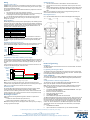
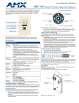
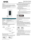
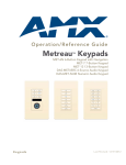
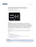
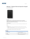
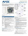
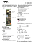
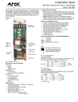
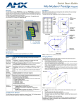
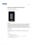
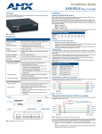
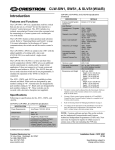
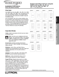
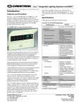
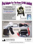
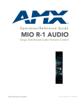
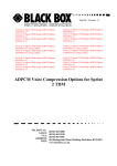
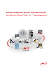
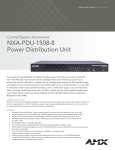
Installation Guide
MET-6N Metreau™ 6-Button Keypad with Navigation
Overview
Navigation Wheel - Pushbuttons
The MET-6N Metreau 6-Button Keypad with Navigation (FG5794-01) features source
control, a navigation wheel that adjusts levels and provides up, down, left, right and
select button options, as well as an LED bar for visual level feedback. The MET-6N
can be used as in individual keypad or in conjunction with the MET-7 and MET-13
keypads (FIG. 1).
The top, bottom, left, right and center points on the Navigation Wheel are pushbuttons
that provide events on Channels #7, #8, #9, #10 and #11, and can be programmed like
any other AxLink button. FIG. 2 shows the button layout of the Navigation Wheel:
Directional pushbutton UP
Rotate counter-clockwise
= button #13
6 pre-printed pushbuttons
(with blue LED indicators)
1
2
3
4
5
6
IR Sensor located here
(supports AMX IR 38kHz)
LED Bargraph
(provides level feedback)
Navigation Wheel
& pushbuttons
FIG. 1 MET-6N Metreau 6-Button Keypad with Navigation
The MET-6N is an AxLink keypad, suitable for use in NetLinx Control Systems.
Specifications
MET-6N Specifications
Power:
12 VDC, 75 mA
Front Panel
Components:
• Pushbuttons - 6 tactile pushbuttons with blue LED indicators that
illuminate when pressed to confirm the source/function was
selected and that it is currently being used. These pre-printed
buttons are field-replaceable.
• IR Sensor - Supports standard AMX IR (38 kHz only).
• LED Levels Indicator - set of 7 blue LEDs provide level feedback.
• Navigation Wheel - consists of 5 pushbuttons: 4 directional
pushbuttons (Up, Down, Right, Left), 1 center pushbutton, and
bi-directional rotating wheel for channel adjustments.
The Navigation wheel itself provides two button functions as well
(rotate CW = button #12, and rotate CCW = button #13, as
indicated in FIG. 2).
Rear Panel
Components:
• DIP switch - 8 position mini DIP switch used to set the device
address for the keypad on the AxLink Bus (1-255).
• AxLink connector - 4 pin 3.5mm Phoenix connector for AxLink
connection to the NetLinx Master.
Dimensions
(HWD):
• Keypad and Mounting Plate: 4.055" x 1.772" x 0.997"
(103mm x 45mm x 25.32mm)
• Mounts into standard decora-style wall plates.
Weight:
2.4 oz. (68.04 g)
Operating
Environment:
• Operating Temperature: 32° - 104° F (0°- 40° C).
• Relative Humidity: 5% - 85%, non-condensing.
• Intended for indoor use only.
Certifications:
•
•
•
•
Colors:
• White (FG5794-01-WH)
• Black (FG5794-01-BL)
• Light Almond (FG5794-01-LA)
Optional
Accessories:
• Single Button Kit (FG5794-10)
• Lutron Cairo Wallplates (available in a variety of sizes and
colors)
FCC Class B
CE
IEC60950
RoHS
Rotate clockwise
= button #12
7
9
Directional pushbutton
LEFT
10
11
Directional pushbutton
RIGHT
8
Center pushbutton
Directional pushbutton DOWN
FIG. 2 Navigation Wheel - button layout
Navigation Wheel
The Navigation Wheel itself can be rotated clockwise and counterclockwise, and is
intended to provide level control (for example volume or lighting levels).
• When rotated clockwise, the Navigation Wheel provides a channel event on
button #12.
• When rotated counter-clockwise, the Navigation Wheel provides a channel
event on button #13.
• The light on the Navigation Wheel can be illuminated by activating channel #11.
Installation
Note: Before touching the device, discharge the static electricity from your body by
touching a grounded metal object.
FIG. 3 shows the basic rear components of the MET-6N keypads:
Mounting Plate
not used
AxLink connector
(from NetLinx Controller)
Device Address
DIP Switch
not used
not used
FIG. 3 MET-6N - Rear Components
AxLink Device Addressing
AxLink-enabled Metreau keypads use an 8-position mini-DIP switch to specify a
unique device address for each keypad in a NetLinx Control System.
Note: Before touching the device, discharge the static electricity from your body by
touching a grounded metal object.
1.
If connected, disconnect the power supply.
2.
Locate the 8-position mini-DIP switch on the rear panel (see FIG. 3).
3.
Set the DIP switch according to the values shown in FIG. 4.
Switch 1
Value 1
2
2
3
4
4
8
5 6 7 8
16 32 64 128
Example
(129)
FIG. 4 8-position mini-DIP Switch
The device number is set by the total value of DIP switch positions that are in the ON
position. Note that the ON position is indicated on the DIP Switch. As an example, the
DIP switch in FIG. 4 defines AXLink device number 129 (1+128=129).
If you later change the device number, remove and reconnect the power connector to
enter the new device number into memory.
Wiring
Wallbox Mounting
Preparing captive wires
1.
2.
Caution: Do not connect power to the Metreau keypad until the wiring is complete.
Caution: If using power from AxLink, disconnect the wiring from the control system
before wiring the Metreau keypads.
You will need a wire stripper, and flat-blade screwdriver to prepare and connect the
captive wires.
1.
Strip 0.25 inch (6.35 mm) of wire insulation off all wires.
2.
Insert each wire into the appropriate opening on the connector according to the
wiring diagrams and connector types described in this section.
3.
Turn the flat-head screws clockwise to secure the wires in the connector.
Note: Do not over-torque the screws; doing so can bend the seating pins and
damage the connector.
Use the cutout dimension for the wallbox to cutout the install surface.
Connect the AxLink connector (or SWT cable connectors) to the rear of the
keypad.
3.
Place the Mounting Plate on the wallbox; align the screw holes with the mounting holes and fasten the Mounting Plate to the wallbox using the screws supplied.
Note: Do not overtighten the screws when mounting the Mounting Frame. The
device should be flush with mounting surface.
Mounting Dimensions
FIG. 7 provides detailed dimensions for the 6-button/Navigation Wheel keypads.
Wiring guidelines
Metreau keypads require 12 VDC power to operate properly. The necessary power is
supplied via the AxLink or SWT cable. The maximum wiring distance is determined
by power consumption, supplied voltage, and the wire gauge used for the cable. The
following table lists wire sizes and the maximum lengths allowable based on the
maximum power consumption rating of 170 mA.
AxLink Wiring Guidelines at 170 mA
Wire Size
18 AWG
20 AWG
22 AWG
24 AWG
Maximum Wiring Length
690.42 feet (210.43 m)
436.80 feet (133.13 m)
272.33 feet (83.00 m)
171.66 feet (52.32 m)
The maximum wiring lengths for using AxLink power are based on a minimum of
13.5 volts available. If the distance is greater than what is listed in the table, consult
the Metreau Keypads Operation/Reference Guide for wiring with external power
sources.
AxLink Data and Power Connections
Connect the control system's AxLink connector to the AxLink connector on the rear
panel of the Metreau Keypad for data and 12 VDC power as shown in FIG. 5.
PWR +
AXP
AXM
GND -
PWR +
AXP
AXM
GND -
Control System
Metreau Keypad
FIG. 5 AxLink straight-thru wiring
Using AxLink for Data with an Auxiliary Power Supply
Use an auxiliary 12 VDC power supply when the distance between the controller and
server exceeds the limits described in the Wiring guidelines section. Connect only
the GND (-) wire on the AxLink connector when using an auxiliary 12 VDC power
supply.
Connect the NetLinx Controller’s AxLink connector to the AxLink connector on the
rear panel of the Metreau keypad, as shown in FIG. 6.
FIG. 7 Mounting Dimensions - MET-6N
NetLinx Programming
DEVICE IDs
The MET-6N utilizes two distinct Device IDs: One for the device itself, and another
for the IR Sensor.
12 VDC power supply
PWR (+)
Programming the Navigation Wheel
GND (-)
PWR +
AXP
AXM
GND -
PWR +
AXP
AXM
GND -
NetLinx Controller
Metreau keypad
The Navigation wheel on the MET-6N can be treated from a NetLinx programming
perspective as 5 distinct pushbuttons plus Channel up and down. The button layout
for the Navigation Wheel is indicated in FIG. 2.
SEND_COMMANDs
There are a select number or SEND_COMMANDs the Metreau keypad recognizes.
For a full list and descriptions, consult the Metreau Keypads Operation/Reference
Guide.
FIG. 6 AxLink and 12 VDC power supply wiring diagram
Sending Firmware to Metreau Keypads (AxLink)
Note: If you are not using power from AxLink, disconnect the wiring from the
controller before wiring the Metreau keypad. Make sure the auxiliary power supply’s
PWR (+) is not connected to the controller’s AxLink connector.
The Firmware on the AxLink-enabled Metreau keypads (MET-6N, MET-7 and
MET-13) can be updated via the NetLinx Studio2 application:
Note: Refer to the NetLinx Studio 2 online help for additional details on firmware
transfers. NetLinx Studio 2 is available for free download from www.amx.com.
1.
Open NetLinx Studio2.
2.
Go to Tools > Firmware Transfers > Send to Axcess Device... This opens
the Send to Axcess Dialog Window.
3.
Browse to the location of the firmware file.
4.
Select the file within the Files frame.
5.
Click Query for Devices.
6.
Select the Metreau keypad within the Devices frame.
The MET-6N will appear as two devices in the Devices frame, because it’s built-in IR
Receiver is recognized as a separate online device.The Device Address of the IR
Receiver is always one number higher than the device number of the keypad itself
(to which the firmware is uploaded). For example, if the MET-6N is set to device
number 127, then the IR Receiver on that MET-6N will appear as device number
128. Firmware must be sent to the keypad, not the IR Receiver (in this example,
device 127).
7.
Click Send and then Close.
8.
Upon confirmation of a successful send, you can exit NetLinx Studio2.
AxLink Status LED
The AxLink Status LED (located next to the AxLink connector), lights to indicate
AxLink power/data status (see Operation / Reference Guide for details).
If the LED is on and not flashing, disconnect the AxLink connector and recheck all
AxLink connections. Then, reconnect the AxLink connector to the panel and verify
the LED is flashing once per second.
Mounting Procedures
AMX recommends mounting Metreau keypads in standard U.S.-style decora
wallboxes:
• Conduit box should meet NEC specs (section 370)
• Minimum internal clearance of (HWD) 2-5/8" x 1-3/4" x 1-5/8".
Note: Before touching the device, discharge the static electricity from your body by
touching a grounded metal object.
For full warranty information, refer to the AMX Instruction Manual(s) associated with your Product(s).
1/08
©2008 AMX. All rights reserved. AMX and the AMX logo are registered trademarks of AMX.
AMX reserves the right to alter specifications without notice at any time.
3000 RESEARCH DRIVE, RICHARDSON, TX 75082 • 800.222.0193 • fax 469.624.7153 • technical support 800.932.6993 • www.amx.com
93-5794-01
REV: B