1
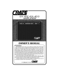
Owner’s Guide
for the
SVT-150H
Bass Amplifier
Made in the U.S.A.
by
SVT-150H
TABLE OF CONTENTS
Introduction . . . . . . . . . . . . . . . . . . . . . . . . . . . . . .2
Features . . . . . . . . . . . . . . . . . . . . . . . . . . . . . . . .2
Important Safeguards and Precautions . . . . . . . . . .2
The Front Panel Controls and Their Use . . . . . . .3,4
The Rear Panel . . . . . . . . . . . . . . . . . . . . . . . . . .4,5
Some Suggested Settings . . . . . . . . . . . . . . . . . . .6
Troubleshooting . . . . . . . . . . . . . . . . . . . . . . . . . . .7
System Block Diagram . . . . . . . . . . . . . . . . . . . . . .7
Technical Specifications . . . . . . . . . . . . .back cover
An Introduction to your new Ampeg
SVT-150H Bass Amplifier
Features
In the world of high performance bass amps, Ampeg amplifiers
stand alone. In true Ampeg tradition, your new SVT-150H offers you
more power, performance and flexibility than any other bass amplifier in its class. Here are just some of the outstanding features of
your new amplifier - features which set it apart from the competition!
First of all, thank you for making what could be one of
the best choices you could ever make concerning your
musical career - choosing one of the finest bass amplifiers
available, an Ampeg SVT-150H.
Your new bass amplifier offers you many outstanding
features, such as 150 watts of pure bass energy, total tone
control and rugged construction which make it a true performer’s bass amp.
• 9-BAND GRAPHIC EQ: Use as a “second channel” for bass solos, or to
shape your sound to your own exacting standards.
• BALANCED LINE OUTPUT: XLR with independent level control switch
to patch into house consoles, mixing boards, or external power amplifiers.
• EFFECTS LOOP: For increased intensity and quieter operation of external effects.
• DRIVE CONTROL: To add harmonic content for tube-like overdrive.
Important Safeguards and Precautions
All Ampeg products are designed for continuous safe operation, as long as common sense is used and steps are taken to help
avoid certain problems. Abiding by the following rules can help prevent damage to your amplifier, yourself and others.
• The amplifier is equipped with a three-pronged AC power cord. To reduce the risk of electrical shock, NEVER remove or otherwise
attempt to defeat the ground pin of the power cord.
• Connect the amplifier ONLY to a properly grounded AC outlet of the proper voltage for your amp.
• Avoid sudden temperature extremes, rain and moisture. Also, avoid sudden and intense impact. (If the unit has been subjected to any
of the preceeding abuses, have it looked at by an authorized service center.)
• NEVER set the amplifier on a support that might give out under its weight.
• Always keep the total speaker impedance at or above the rated load.
• Unplug the amplifier before cleaning it. NEVER spray liquid cleaners onto the amplifier. Wipe it with a slightly dampened, lint-free cloth
to remove dirt and film.
• Don’t use the amplifier if it has sustained damage to the chassis, controls, or power cord. Refer the unit to an authorized service center for inspection.
• Amplifiers capable of producing high volume levels are also capable of inflicting permanent hearing loss or damage, if the exposure to
such levels is prolonged. Such damage is progressive and irreversible!
CAUTION
ATTENTION
VORSICHT
RISK OF ELECTRIC SHOCK
DO NOT OPEN
RISQUE D'ELECTROCUTION
NE PAS OUVRIR
ELEKTRISCHE SCHLAGGEFAHR
NICHT OFFENEN
CAUTION: TO REDUCE THE RISK OF ELECTRIC SHOCK,
DO NOT REMOVE COVER.
NO USER-SERVICEABLE PARTS INSIDE.
REFER SERVICING TO QUALIFIED SERVICE PERSONNEL.
ATTENTION: POUR REDUIRE D'ELECTROCUTION NE PAS
ENLEVER LE COUVERCLE. AUCUNE PIECE INTERNE N'EST REPRABLE
PAR L'UTILISATEUR. POUR TOUTE REPARATION, S'ADRESSER A UN
TECHNICIEN QUALIFIE.
VORSICHT: ZUR MINIMIERUNG ELEKTRISCHER SCHLAGGEFAHR NICHT
DEN DECKEL ABENHMEN. INTERNE TEILE KONNEN NICHT VOM
BENUTZER GEWARTET WERDEN. DIE WARTUNG IS QUALIFIZIERTEM
WARTUNGSPERSONAL ZU UBERLASSEN.
THIS EQUIPMENT HAS BEEN DESIGNED AND ENGINEERED TO PROVIDE SAFE AND RELIABLE OPERATION. IN ORDER TO PROLONG THE LIFE OF THE UNIT AND PREVENT ACCIDENTAL DAMAGES OR INJURY, PLEASE FOLLOW THESE PRECAUTIONARY GUIDELINES:
WARNING: TO REDUCE THE RISK OF ELECTRIC SHOCK, DO NOT OPEN CHASSIS; DO NOT DEFEAT OR REMOVE THE GROUND PIN OF THE POWER CORD; CONNECT ONLY TO A PROPERLY GROUNDED AC POWER OUTLET.
CAUTION: TO REDUCE THE RISK OF FIRE OR ELECTRIC SHOCK, DO NOT EXPOSE THIS EQUIPMENT TO RAIN OR MOISTURE.
CAUTION: NO USER-SERVICEABLE PARTS INSIDE. REFER SERVICING TO QUALIFIED SERVICE PERSONNEL.
CAUTION: OUR AMPLIFIERS ARE CAPABLE OF PRODUCING HIGH SOUND PRESSURE LEVELS. CONTINUED EXPOSURE TO HIGH SOUND PRESSURE LEVELS CAN CAUSE PERMANENT
HEARING IMPAIRMENT OR LOSS. USER CAUTION IS ADVISED AND EAR PROTECTION IS RECOMMENDED IF UNIT IS OPERATED AT HIGH VOLUME. The chart below shows the U.S.
Government Occupational Safety and Health Administration (OSHA) regulations which were in effect at the time of this publication for permissible noise exposure, per 29CRF1910, Table G-16.
SOUND LEVEL dBA
SLOW RESPONSE
DURATION PER DAY
IN HOURS
SOUND LEVEL dBA
SLOW RESPONSE
DURATION PER DAY
IN HOURS
90
92
95
97
100
8
6
4
3
2
102
105
110
115
1-1/2
1
1/2
1/4 or less
According to OSHA, any exposure in excess of those listed above could result in some hearing loss.
2
EXPLANATION OF
GRAPHICAL SYMBOLS:
"DANGEROUS VOLTAGE"
= "DANGER HAUTE TENSION"
"GEFAHLICHE SPANNUNG"
"IT IS NECESSARY FOR THE USER TO REFER TO THE INSTRUCTION MANUAL"
= "REFERREZ-VOUS AU MANUAL D'UTILISATION"
"UNBEDINGT IN DER BEDIENUNGSANLEITUNG NACHSCHLAGEN"
SVT-150H
The Front Panel Controls and Their Use
1
2
3
4
5
6
7
1. INPUT: Connect your bass guitar here
using a shielded instrument cable.
2. -15dB PAD: If your bass has high-output
pickups or active electronics you may notice
the Peak LED (#3) flashes or stays on even at
low settings of the Gain control (#4). To keep
the signal clean, switch in the Pad. This will
attenuate the input signal to the preamp allowing you to get the best signal to noise ratio for
your bass.
8
9
10
11
clockwise, signal level is increased to drive the
preamp harder (into distortion). The tone of
the signal is also changed to provide a
smoother overdrive. The tone controls may
have to be readjusted to obtain the overall
desired tone. The Gain control (#4) and -15dB
Pad (#2) interact with the Drive control. For
greater overdrive, the Pad switch should be
out and the Drive control fully clockwise. Use
the Gain control to set the amount of overdrive
desired. The Peak LED (#3) will glow steadily
when the amp is used in this manner.
3. PEAK LED: This LED lights whenever any
preamp stage is near the point of being over- 6. BASS: This knob serves as the primary low
driven. Adjust the Gain control (#4) until a frequency control. This allows for a range of
strong signal from your bass causes this LED 8dB of cut or boost at 50Hz.
to flicker.
7. ULTRA-MID: This is the primary midrange
NOTE: If the LED stays on with the Gain at a control. Rotate the control to the left of center
low setting, use the 15dB Pad (#2) to attenu- for a “contoured” sound (more distant, less
ate the input signal and readjust the Gain.
midrange output) or to the right of center for a
4. GAIN: This serves as the input level control sound that really cuts through.
12
13
14
10. GRAPHIC EQ: These slide controls allow
you to adjust the output of the frequencies
shown beside each control. The center position of each control is flat (no boost or cut).
These controls only affect the sound when the
EQ is turned on.
11. MASTER: Set the overall output level of
the amplifier with this control. The Effects
Loop and Balanced Out (#18, 19, 22) are not
affected by the Master control. Pulling the
Master control turns on the Graphic EQ (#10).
When the footswitch is used, the front panel
switch is bypassed.
12. LIMIT LED: This LED indicator will flash
on any time the internal limit circuit is called
upon to keep amplifier’s output signal clean.
This indicates that the amplifier is nearing full
output and the limiter is keeping it from clipping the output signal.
13. POWER ON LED: This LED indicator
for the amplifier. For the best signal-to-noise 8. TREBLE: This knob serves as the primary lights when the POWER switch (#14) is
ratio set this control so the Peak LED (#3) high frequency control. This allows for a range turned on.
flashes when you strike a string fairly hard.
of 17dB boost or 22dB cut at 5kHz.
14. POWER SWITCH: This heavy-duty rock5. DRIVE: This control is used to overdrive the 9. EQ ON LED: This LED indicator lights er switch applies AC power to the amplifier:
preamp in order to get various harmonic when you engage the EQ by the front panel the amp is ON in the up position, OFF in the
enhancement or distortion sounds. In the fully Master control (#11) or the footswitch (#23, down position.
counterclockwise position the preamp is in the rear panel).
cleanest condition. As the control is rotated
1. ENTRADA: Conecte aquí su guitarra de bajos
usando un cable blindado para instrumentos.
NOTA: Si el LED permanece iluminado aún con la
Ganancia en una posición baja, utilice la Terminal
de -15 dB (#2) para atenuar la señal de entrada y
2. TERMINAL DE -15 dB: Si su bajo tiene capta- reajuste la Ganancia.
dores de alta salida ó circuitos electrónicos activos,
usted tal vez notará que el díodo (LED) de Picos 4. GANANCIA: Esto sirve como el control de
(#3) parpadea ó permanece iluminado aún en posi- nivel de entrada para el amplificador. Para lograr la
ciones bajas del control de Ganancia (#4). Conecte mejor relación de señal-a-ruido fije este control para
esta Terminal para conservar limpia la señal. Esto que el LED de Picos (#3) parpadee cuando usted
atenuará la señal de entrada hacia el preamplifi- pulse con fuerza alguna cuerda.
cador, lo que le permitirá obtener la mejor relación
5. IMPULSO: Este control se usa para sobreimde señal-a-ruido para su bajo.
pulsar el preamplificador a fin de conseguir varios
3. DIODO (LED) DE PICOS: Este LED se ilumi- realces armónicos ó sonidos de distorsión. En la
nará cuando cualquier etapa de preamplificación se posición totalmente contraria a las manecillas del
encuentre cerca del punto de sobreimpulso. Ajuste reloj, el preamplificador se encontrará en la posición
el control de Ganancia (#4) hasta que una señal más “limpia”. Conforme el control se gire a favor de
fuerte de su bajo cause un parpadeo de este LED. las mane-cillas del reloj, el nivel de la señal se
incrementará para impulsar el preamplificador con
mayor fuerza (hacia la distorsión). El tono de la
señal también cambia para proveer un sobreimpulso más suave. Tal vez tengan que ajustarse los
controles de tono para obtener el tono general
deseado. El control de Ganancia (#4) y la Terminal
de -15 dB (#2) interaccionan con el control de
Impulso. Para un sobreimpulso mayor, el interruptor
de la Terminal debe estar apagado y el control de
Impulso totalmente a favor de las manecillas del
reloj. Use el control de Ganancia para fijar la cantidad deseada de sobreimpulso. El díodo LED de
Picos (#3) se iluminará en forma constante cuando
el amplificadora se utilice de esta manera.
6. BAJOS: Esta perilla sirve como el control primordial para las frecuencias bajas. Esto permite un
rango de 8dB de recorte ó de refuerzo a 50Hz.
3
SVT-150H
The Front Panel Controls and Their Use
7. ULTRA-MEDIANOS: Este es el control primordial para el rango de las frecuencias medianas. Gire
el control del centro hacia la izquierda para lograr
un sonido de contorno (más distante, menor salida
en el rango mediano) ó del centro hacia la derecha
para obtener un sonido realmente penetrante.
10. EQ GRAFICO: Estos controles deslizantes
(cursores) le permiten ajustar la salida de las frecuencias que se muestran junto a cada control. La
posición central de cada control es plana (sin
refuerzo ni recorte). Estos controles sólo afectan el
sonido cuando el EQ esé prendido.
8. AGUDOS: Esta perilla sirve como el control primordial para las frecuencias altas. Esto permite un
rango de 17 dB de refuerzo ó 22dB de recorte a
5kHz.
11. MAESTRO: Fije mediante este control el nivel
general de salida del amplificador. El Circuito de
Efectos y la Salida Equilibrada (#18, 19, 22) no se
verán afectadas por el control Maestro. Jalando el
control Maestro se prende el EQ Gráfico (#10).
Cuando se utiliza el interruptor de pie, se pasa por
alto el interruptor del panel delantero.
9. EQ EN LED: Este LED indicador se ilumina
cuando usted activa el EQ mediante el control
Maestro (#11) del panel delantero ó el interruptor de
pie (#23) del panel posterior.
12. DIODO LED DE LIMITE: Este LED indicador
parpadeará cada vez que se requiera el circuito limitador interno para conservar limpia la señal de salida del amplificador. Esto indica que el amplificador
está aproximándose a su salida máxima y que el
limitador está impidiendo el aplanamiento (“clipping”) de la señal de salida.
13. DIODO LED DE POTENCIA ENCENDIDA:
Este LED indicador se ilumina cuando se prende el
interruptor de POTENCIA (#14).
14. INTERRUPTOR DE POTENCIA: Este interruptor de servicio pesado tipo vaivén aplica la energía
de CA al amplificador: el amplificador se PRENDE
en la posición hacia arriba, y se APAGA en la posición hacia abajo
The Rear Panel
Made in the U.S.A. by SLM ELECTRONICS
1400 Ferguson Avenue • St. Louis, MO 63133
15
16
17
15. FUSE: This protects the unit from damage due to overload conditions or power
line surges. If the fuse blows, replace it only
with the same size and type.
18. EFFECTS RETURN: To use an external
effects device or other signal processor,
connect the OUTPUT of the device to this
jack using a shielded cable. This feeds the
processed signal into the amplifier’s master
16. AC LINE IN: Firmly plug the supplied section.
AC power cord into this socket, pushing it in
until it is fully seated. Plug the male end of 19. EFFECTS SEND: Connect the output
the cord into a grounded AC outlet. DO from this jack to the INPUT of an external
NOT DEFEAT THE GROUND PRONG OF effects device using a shielded cable. This
THE AC PLUG!
sends a post-EQ signal to your effects.
Since plugging a cable in here does not
17. SPEAKER OUTPUT(S): The SVT- break the through connection to the power
150H has two 1/4” speaker output jacks amp, this can be used as another line out.
which you will use to connect to your bass
cabinet(s). Use speaker cables with 1/4” 20. PRE/POST SWITCH: You can select
plugs to connect the SPEAKER jack(s) to either pre or post-EQ for the signal at the
the cabinet(s). Observe the 4 ohm minimum Balanced Out jack (#22) with this switch.
impedance rating. Please see the note With the switch in the OUT position, the sigconcerning the speaker output jacks on nal at the jacks will be pre-EQ. This is a
the facing page.
direct output which is not affected by any
EQ or boost settings. With the switch in, the
The following chart shows the total signal is post-EQ and is controlled and
impedance load when connecting speaker modified by the tone controls, Graphic EQ
cabinets in parallel:
and Effects Loop.
4
Cabinet
Impedance
# of
Cabs
Total
Impedance
8Ω
16Ω
16Ω
2
2
4
4Ω
8Ω
4Ω
18
19 20
21
22
23
21. -20dB SWITCH: This switch adjusts the
output level at the Balanced Out jack (#22).
The switch works independently from the
front panel Master control. Pushing the
switch in activates the -20dB pad, allowing
patching into microphone inputs on a mixer
without overdriving them.
22. BALANCED OUT: This XLR-type connection supplies a balanced preamp output
signal for connecting to a house mixing
board, recording console or external amplifiers with balanced inputs. The signal can be
set to pre or post-EQ by the Pre/Post switch
(#20). The level can be adjusted for either
mic or line type inputs using the -20dB
switch (#21).
23. FOOTSWITCH: This jack accepts the
1/4” plug from a 1-button footswitch, allowing remote control of the Graphic EQ on/off
function. When a footswitch is used, the
front panel Master Pull EQ On switch (#11)
is bypassed.
SVT-150H
The Rear Panel
22. SALIDA EQUILIBRADA: Esta conexión
tipo XLR proporciona una señal de salida
equilibrada de preamplificación para conectarse a un tablero mezclador local, una consola grabadora ó amplificadores externos
con entradas equilibradas. La señal se puede
16. ENTRADA DE LA LINEA DE CA:
establecer como pre ó post-EQ mediante el
Conecte firmemente a este receptáculo el 19. ENVIO DE EFECTOS: Conecte la salida interruptor Pre / Post (#20). El nivel se puede
cable suministrado de corriente de CA, oprim- de este “jack” a la ENTRADA de un dispositi- ajustar para entradas de tipos ya sean de
iéndolo hasta que quede totalmente asenta- vo de efectos externo usando un cable blinda- micrófono ó de línea utilizando el interruptor
do. Enchufe el extremo macho del cordón a do. Esto envía una señal post-EQ a sus efec- de -20dB (#21).
una salida aterrizada de CA. ¡NO PASE POR tos. Siendo que la conexión de un cable en
ALTO EL BORNE DE TIERRA DE LA CLAV- este lugar no rompe la conexión directa al 23. INTERRUPTOR DE PIE: Este “jack”
IJA DE CA!
amplificador de potencia, esto se puede uti- acepta la clavija de 1/4” de un interruptor de
pie de un solo botón, lo que permite un conlizar como otra linea hacia afuera.
17. SALIDA(S) DE LA(S) BOCINA(S): El
trol remoto de la función de prender / apagar
SVT-150H tiene dos “jacks” de salida para 20. INTERRUPTOR PRE/POST: Usted del EQ Gráfico. Cuando se utiliza un interrupbocinas que usted usará para conectarse a puede seleccionar por medio de este inter- tor de pie, se pasa por alto el interruptor
su(s) gabinete(s) de bajos. Use cables para ruptor ya sea pre ó post-EQ para la señal en Maestro para Prender ó Jalar el EQ (#11).
bocinas con clavijas de 1/4” para conectar el el “jack” de Salida Equilibrada (#22). Con el
(los) “jack(s)” de la(s) BOCINA(S) al (los) interruptor en la posición de FUERA, la señal
gabinete(s). Observe la especificación de 4 en los “jacks” será pre-EQ. Esta es una salida
directa no afectada por ningunas posiciones
ohms de impedancia mínima.
del EQ ó de refuerzo. Con el interruptor hacia
La tabla a continuación muestra la carga adentro, la señal es post-EQ y se controla y
de impedancia total cuando se conecten gabi- modifica mediante los controles de tono, el
netes de bocinas en paralelo:
EQ Gráfico y el Circuito de Efectos.
15. FUSIBLE: Esto protege a la unidad contra daños debidos a condiciones de sobrecarga ó sobretensiones transitorias en la línea de
energía. Si el fusible se quema, repóngalo
sólo con el mismo tipo y tamaño.
Impedancia de
cada Gabinete
# de
Gabinetes
Impedancia
Total
8 ohms
16 ohms
16 ohms
2
2
4
4 ohms
8 ohms
4 ohms
18. RETORNO DE EFECTOS: Para utilizar
un dispositivo de efectos externo ú otro procesador de señales, conecte la SALIDA del dispositivo a este “jack” usando un cable blindado. Esto alimenta la señal procesada a la sección maestra del amplificador.
21. INTERRUPTOR DE -20dB: Este interruptor ajusta el nivel de salida en el “jack” de
Salida Equilibrada (#22). El interruptor funciona independientemente del control
Maestro del panel delantero. Al oprimirse el
interruptor hacia adentro se activa la terminal
de los -20dB, lo que permite conectarse a las
entradas para micrófonos en un mezclador
sin sobreimpulsarlos.
NOTE: In some areas 1/4” speaker jacks are
not acceptable for use on amplifiers capable of high output power levels. For this reason the Speaker jacks on your amplifier
may resemble the illustration to the right.
Connect the amplifier to your speaker(s)
using cables rated for very high output
power, terminated with the appropriate connectors.
5
SVT-150H
Some Suggested Settings
ROCK:
JAZZ:
COUNTRY:
FUNK “POPPING:”
6
The setting of the Gain control depends on your particular instrument. The
Master should be set to produce the appropriate output volume level. The
Graphic EQ can be used to tailor the amplifier to your speaker cabinets, to
compensate for room acoustics and to “fine tune” your sound.
SVT-150H
Troubleshooting
In the unlikely event that you SVT-150H should stop working properly (or just stop working), take a few minutes to troubleshoot it before you call for service. You can save yourself a lot of time and sometimes money by doing it yourself, and
often the cure for the problem is something quite simple.
NO SOUND
POOR SOUND
LEDs LIGHT
LEDs DON'T LIGHT
Check bass, cables
Check amp controls, check
for signal from bass
Check AC outlet
POOR SOUND
OUTLET OK NO OUTLET
Check speaker(s)
NO SOUND
SOUND OK
SOUND OK
Check power cord,
fuse, power switch
Listen for hum
NO HUM
HUM
Check speaker
Unplug bass,
touch tip of cable
Check house fusebox
or circuit breaker
SPEAKER(S) OK,
POOR SOUND
OK
Speaker OK
Replace speaker(s)
POOR SOUND
NO CHANGE
LOUD HUM
Replace cable
Check inst. pickup
NO CHANGE
SOUND OK
SOUND OK
SPEAKER(S)
DEFECTIVE
SEE BELOW
SOUND OK
SEE BELOW
If the problem isn’t covered above, or if the steps led you here, then contact your Ampeg dealer for service information. Also, you should refer your amp for servicing if it gets dropped, has liquid spilled into it, or sustains damage to its
power cord (see page 2).
System Block Diagram
PEAK LED
TONES
INPUT
-15dB
GAIN
DRIVE
9 BAND EQ
FOOT
SWITCH
EQ ON
BASS
TREBLE
ULTRA MID
1+
1–
LIMIT LED
SPEAKON®
JACK
MASTER
POWER
AMP
EFFECTS
SEND
EFFECTS
RETURN
POST
SPEAKER
OUTS
2
PRE
-20dB
3
BALANCED
OUT
7
SVT-150H
Technical Specifications
OUTPUT POWER RATING
POWER REQUIREMENTS
150 Watts RMS, 4Ω load, 115VAC
Domestic:
Export:
115VAC, 60Hz, 140VA
100/115VAC, 50/60Hz, 140VA
230VAC 50,60Hz, 140VA
Bass:
Ultra-Mid:
Treble:
±8dB @ 50Hz
+5, -17dB @500HZ
+17, -22dB @ 5KHZ
TONE CONTROL RANGE
GRAPHIC EQ RANGE
40Hz
80Hz
150Hz
300Hz
600Hz
900Hz
2kHz
5kHz
9kHz
GAIN
SIGNAL TO NOISE RATIO
SIZE (W x H x D) AND WEIGHT
±11dB
±8dB
±8dB
±8dB
±8dB
±8dB
±8dB
±9dB
±12dB
66dB typical, tones @ center
75dB typical
19”x9.5”x12.5”, 30 lbs
Ampeg reserves the right to change specifications without notice.
Ampeg is proudly Made in America. ©1997 SLM Electronics, 1400 Ferguson Avenue, St. Louis, MO 63133 U.S.A.
P/N 47-588-52 . 01/97